Air cooling ends at 10–15 kW per rack, and the racks are drawn at 132 kW
The next generation is drawn at 240 kW. Past the point where air stops working, the cooling decision is already made.
What remains is the fluid path: the joints, the filtration and the instrument chain that has to notice a change first. Average rack power density rose 38 % between 2022 and 2024.
On 40 °C facility water.
At 240 kW the coolant inventory is the risk
More racks at a higher density means more fluid in the hall and more joints per megawatt. The joint count per megawatt is the number that rises fastest, because every rack adds a supply leg, a return leg and a pair of couplings to the same manifold.
A leak that would have been a mop-up at 20 kW is a rack-scale event at 240 kW. Detection demand in this category has shifted toward coolant and glycol fluids rather than plain water, because that is what is in the loop.
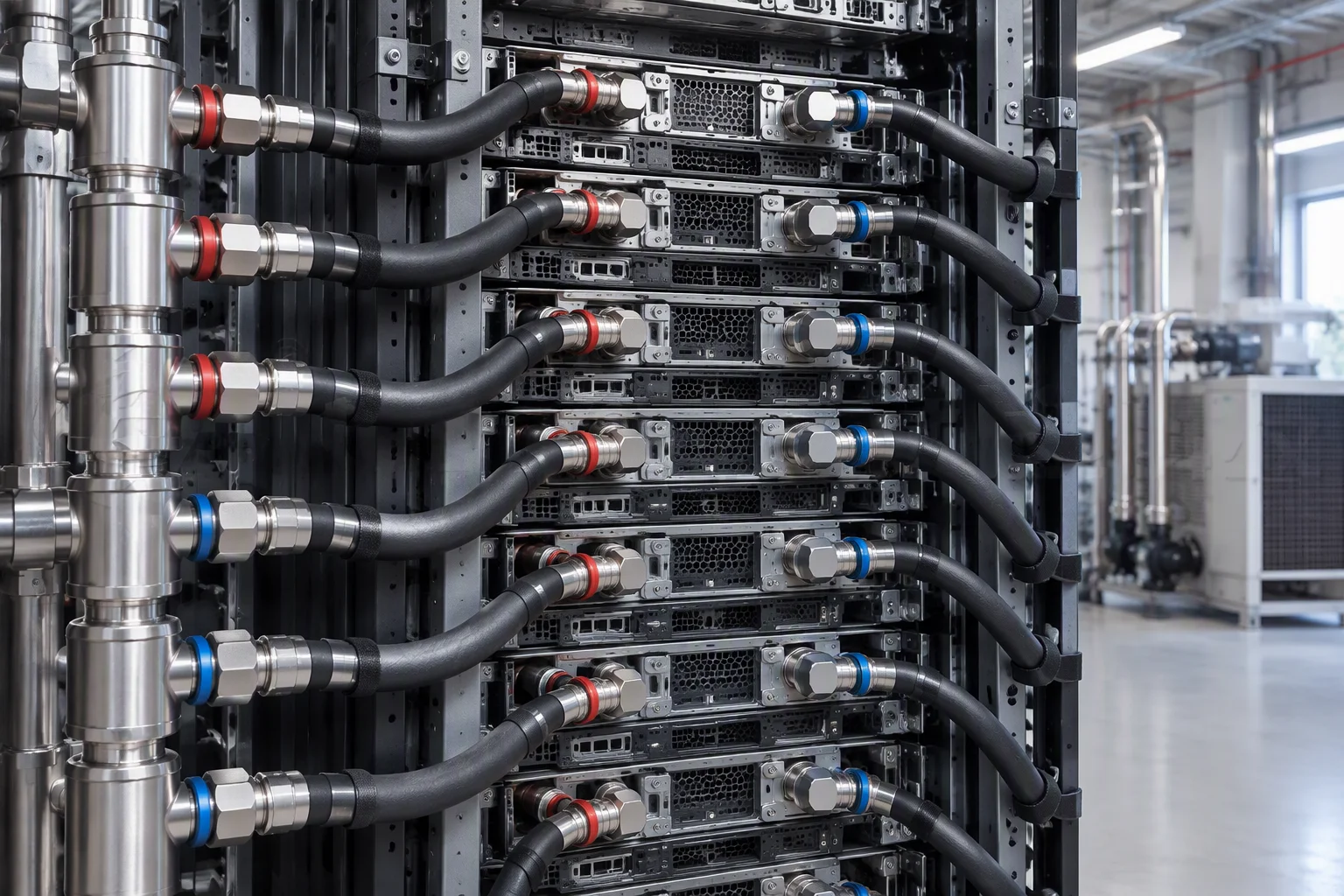
Dense rack · every leg and coupling on this manifold is a joint count
Five measurements, commissioned together against one protocol
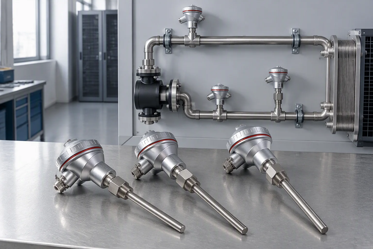
Ordered separately these are five purchase orders, five calibration certificates and five integration tasks. As one kit they arrive commissioned together against one protocol.
| Supply and return temperature | matched pair, −40 to +150 °C |
|---|---|
| Flow | DN25, 0.5–18 m³/h, about 36:1 turndown |
| Differential pressure | ±0.075 % of span |
| Liquid level | optical point switch and analogue reservoir |
| Leak detection | 4-wire channel, detects and locates |
The pair is the reason the kit is one code. A loop temperature difference of a few degrees, read by two unmatched sensors each accurate to about one degree, puts roughly fifty per cent uncertainty into the capacity calculation.
A filter sized for steady state is under-sized for commissioning
Build cadence magnifies the problem: a hall commissioned rack by rack loads the same element repeatedly before the loop ever reaches steady state.
Pick the model codes without leaving the page
Row-level hose runs use the EMS-HP-E8-20 jumper. Every other code below carries its own PDF specification sheet.
| Product line | Model codes | Model codes |
|---|---|---|
| Leak detection | EMS-LD-R500 | EMS-LD-C16 |
| Filtration | EMS-CF-S10 | EMS-CF-F5-10 |
| Instrumentation | EMS-CF-FP-DP | EMS-TL-SDP |
| Telemetry and hose | EMS-TL-K300 | EMS-HP-J4-06-QD |
Send the rack count, the coolant and the target commissioning date
Those three decide the filtration sizing, the telemetry kit class and the lead time. We reply with the specification sheets within one working day.