Compression set and cold flow
Temperature and clamp load. Months to years.
The real risk in a liquid cooling loop is sealing reliability, not heat rejection capability.
We supply the loop, not the CDU. No coolant distribution units, no cold plates.
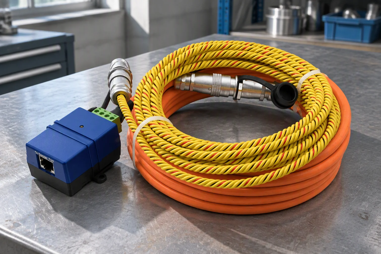
Loop assembly · supply and return manifolds
Heat rejection is sized once, from published curves, at design time. Sealing degrades continuously, through eight mechanisms.
Temperature and clamp load. Months to years.
Coolant chemistry, wall thickness, temperature. Continuous.
Wrong glycol concentration or wrong elastomer. Weeks.
Ambient ozone and UV. Years.
Start and stop events. Thousands of cycles.
Conductivity, chloride, mixed metals. Months.
Filtration state. Weeks.
Pump control and valve actuation. Instantaneous.
Every mechanism on that list is either observed by an instrument or slowed by a consumable.
Six lines cover the loop, each indexed by its deciding number.
| Deciding number | Product line | What it covers |
|---|---|---|
| 0 to 500 m | Leak detection | Detection length per channel. Position resolution 0.1 m. |
| 1 µm | Coolant filtration and water quality | Absolute rating in the cartridge range, with conductivity and pH. |
| 200 psi | EPDM hose and piping | Working pressure −40 to +99 °C, UL 94 V-0 compound. |
| 1.0 to 12 W/m·K | Thermal interface materials | Four material classes, from thermal grease to graphene pad. |
| 5 measurements | CDU telemetry instruments | Supply and return temperature, flow, differential pressure, level and leak. |
| ISO 4406 17/15/12 | Fill and flush | Flush to a target cleanliness code before first power-up. |
Six measurements carry the argument. Each answers a failure that stays invisible until a floor tile is wet.
Points 1 to 6 match the table rows
| Measurement | Instrument | Tells you | Prevents |
|---|---|---|---|
| Locating sensing rope | Where, to 0.1 m position resolution | A wet floor tile three racks away | |
| Conductivity | Inline transmitter | Inhibitor depletion and make-up water ingress | Accelerated galvanic corrosion |
| pH | Inline transmitter | Coolant breakdown | Elastomer attack |
| Differential pressure | Transmitter across the filter | Filter loading | Flow starvation and hot spots |
| Flow | Inline meter | Loop balance | A pump running against a closed valve |
| Liquid level | Level sensor | Make-up rate | Running the reservoir dry |
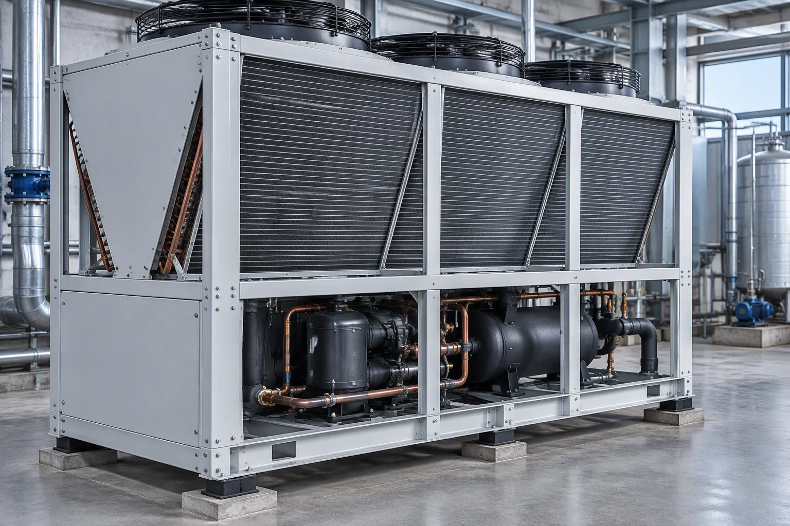
Conductivity is the number on the quote. Bond-line thickness and pump-out decide whether the interface still works in year two.
Conductivity band per class
1.0 to 8.5 W/m·K. Lowest bond line. Pumps out under thermal cycling.
1.5 to 6.0 W/m·K. Accommodates tolerance. Adds bond-line resistance.
3.0 to 8.0 W/m·K. Stable at temperature. Needs a phase-transition window.
5.0 to 12 W/m·K. Highest in-plane. Requires flatness control.
Four figures, each with its basis.
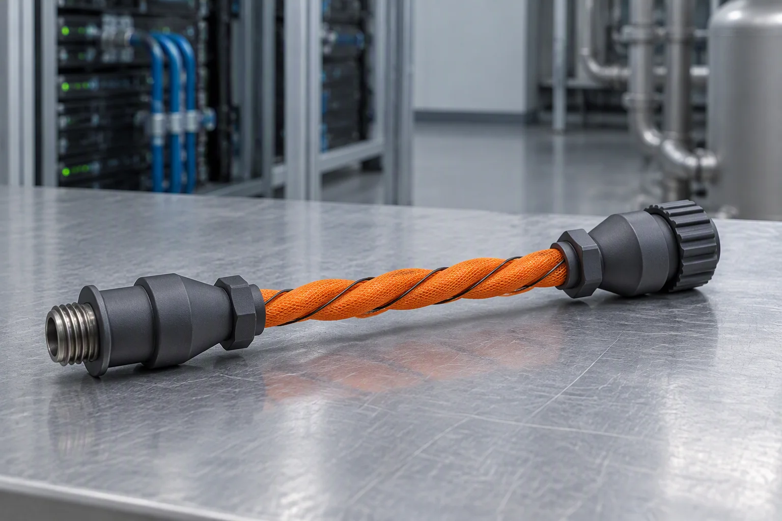
Locating sensing rope. The reported distance step.
Finest absolute rating in the cartridge range.
EPDM. Burst margin on its own row.
Supply and return temperature, flow, differential pressure, level and leak.
Five steps, each with what the buyer supplies.
Order flow · left to right
| Step | What happens | What you send |
|---|---|---|
| 1 | We confirm the model codes. | Fluid, temperature, flow, connection sizes. |
| 2 | The datasheet pack is issued. | The codes you want quoted. |
| 3 | Sample or first-article shipment, with the inspection record. | Your acceptance criteria. |
| 4 | Production run and packaging to the agreed drawing. | The drawing revision to build against. |
| 5 | Reorder by model code. The specification does not drift. | The original model code. |
The application decides which measurement matters first.
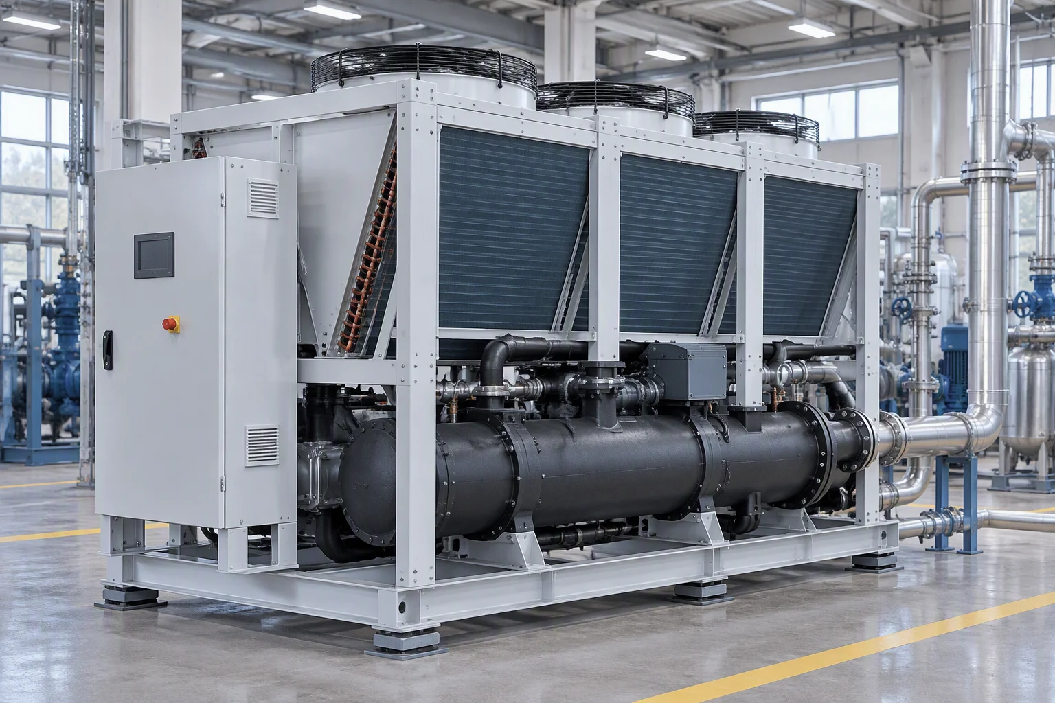
Retrofit into an occupied hall.
Density changes the fluid inventory.
Long-lived loops, mixed generations.
Unattended cabinets, ambient swing.
Water quality and particulate limits.
Test cells and module fixtures.
Six model codes carry the catalogue. Each downloads as its own PDF.
Leave your work email and the model code. One datasheet per model, with position resolution and locating repeatability stated as separate rows.