Thermal interface materials for a liquid cooling loop
Four classes ship from stock.
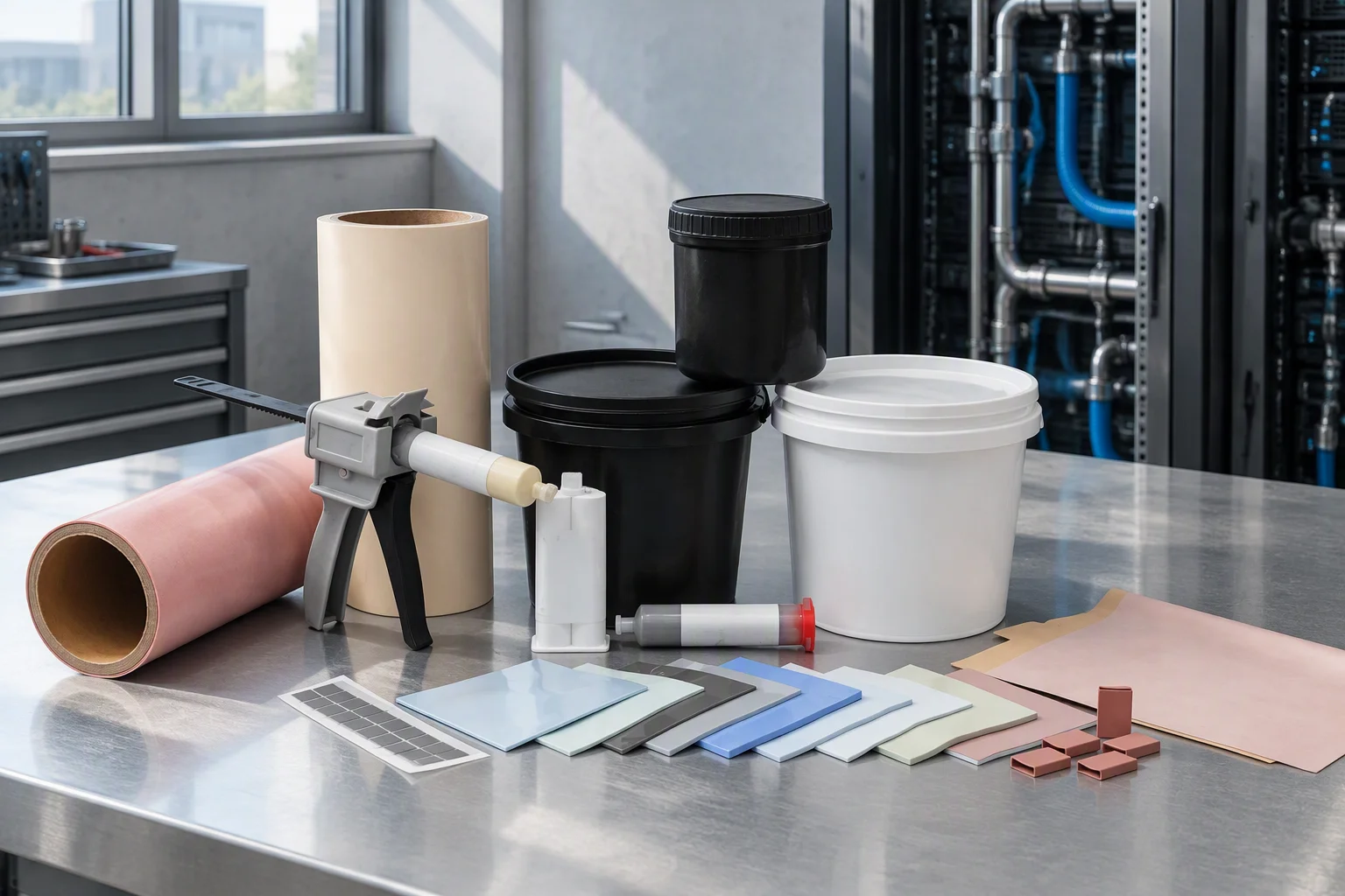
Pick the class
| Class | Stocked band, W/m·K | Ships as | Bond line |
|---|---|---|---|
| Thermal grease | 1.0–6.0 | 1 kg can | from 0.05 mm |
| Gap filler pad | 1.2–7.5 | sheet or roll | 1.0–6.0 mm, to 20 mm |
| Phase change | 2.0–8.5 | die-cut pad | 0.20–1.0 mm |
| Graphene pad | 3.0–15.0 | die-cut pad | 0.25–20 mm |
Through-plane conductivity unless the column says otherwise. In-plane graphene figures print in their own column, never against these numbers.
What ASTM D5470 measures
ASTM D5470 reports apparent thermal impedance at a controlled pressure and thickness. Conductivity comes from repeating that at several thicknesses and regressing: intercept R_con, slope 1/λS.
| Grade | Impedance, °C·in²/W | Test pressure |
|---|---|---|
| Grease, 3.5 W/m·K | 0.020; 0.015 series minimum | 30 psi |
| Pad, 7.5 W/m·K | 0.154–0.539 / 0.074–0.203 / 0.061–0.129 | 10 / 30 / 50 psi |
A W/m·K figure without its test pressure and its thickness is not a specification. A factor of 2 in W/m·K is not one in impedance.
The interface sets the junction temperature
Dry solid-to-solid contact touches under 3 % of the apparent surface area, so interface resistance rather than bulk conductivity governs a real stack. Filling the interface is claimed to cut contact resistance by more than 90 % against a dry joint.
- Grease and phase change reach below 0.05 °C·cm²/W.
- Chip reliability is estimated to fall 5 % for each 1 °C in the 70–80 °C band.
Each class against the failure it is chosen for
| Class | Failure mode | Published measure |
|---|---|---|
| Pump-out from CTE mismatch | 0.05 mm minimum bond line; 0.2 % dry-out at 125 °C | |
| Silicone oil bleed | ≤ 1 % at 25 % compression, 125 °C, 48 h | |
| Transition window off-band | 45–55 °C by ASTM D3418 | |
| In-plane read as through-plane | 130 W/m·K in-plane; 0.8–15 W/m·K through-plane |
Silicone, siloxane and the stocked answer
240+ substances, including D4, D5 and D6.
On request
Ten substances at 0.1 %; cadmium at 0.01 %.
On request
The rating these grades are built to.
On request
- Outgassing, measured: TML 0.170 % and CVCM 0.010 % by ASTM E595.
- Silicone-free grade: 2.0 W/m·K, 45–55 Shore 00, 2.5 g/cc.
Sealing reliability rather than heat rejection is the operating-time risk: 1 % of a pad's mass leaving as silicone oil at 125 °C reaches every elastomer seal downstream.
A ladder with documents behind every row
| Family | Codes | Models | Anchor | Rows |
|---|---|---|---|---|
| Thermal grease | G10 … G60 | 6 | EMS-TM-G35 | 14 |
| Gap filler pad | P12-10 … P75-20 | 15 | EMS-TM-P75-20 | 20 |
| Phase change | PC20 … PC85 | 6 | EMS-TM-PC85 | 13 |
| Graphene pad | GR30 … GR150 | 5 | EMS-TM-GR120 | 13 |
The loop, not the coolant distribution unit
No coolant distribution units. No cold plates. The addressable plane is TIM2: lid or heat-sink base to cold plate, and cold plate to manifold or rail.
Die-cutting runs to the supplied drawing, with a first-article inspection record per order. Sample lead time is 5–10 working days.
Send the gap, the target and the pressure
Gap size in mm · target W/m·K · assembly pressure in psi · isolation requirement in kV/mm. The datasheet, the drawing and the lead time come back within one working day.