
Loop configuration profiles, and the consumables each one carries
Three loop shapes cover most of the liquid cooling work this sheet is indexed on. Each is drawn from the header out, and no customer name and no site name appears on any of them.
The loop profiles, drawn from the header out
A liquid cooling loop is a closed circuit between a heat load and a heat rejection point, and almost everything that goes wrong on it happens at the joints, the filters and the sensors rather than in the coolant. The three profiles below differ in where the branches leave the header and in how many joints that puts in the run.
Read a profile as a consumables schedule rather than as a system diagram. Each band names the shape and the figure the rest of this sheet is indexed on: filtration grade, working pressure, locating resolution, joints per rack. Those four are what a quotation is actually built from.

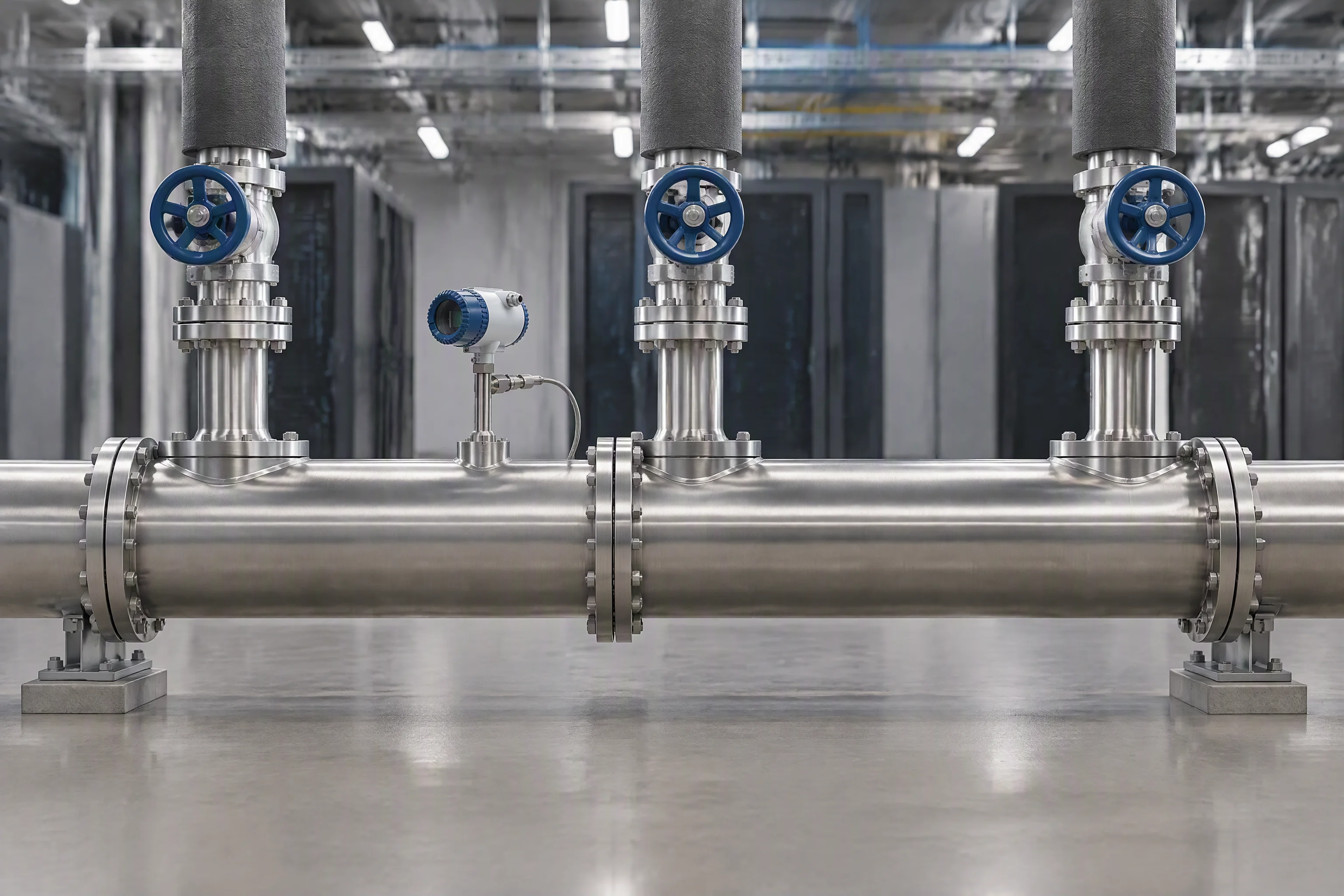
Profile A · row supply and return
One supply header and one return header per row, with a hose drop and a quick disconnect at each rack in both directions.
Bore 6.1–15.8 mmUQD at each rack
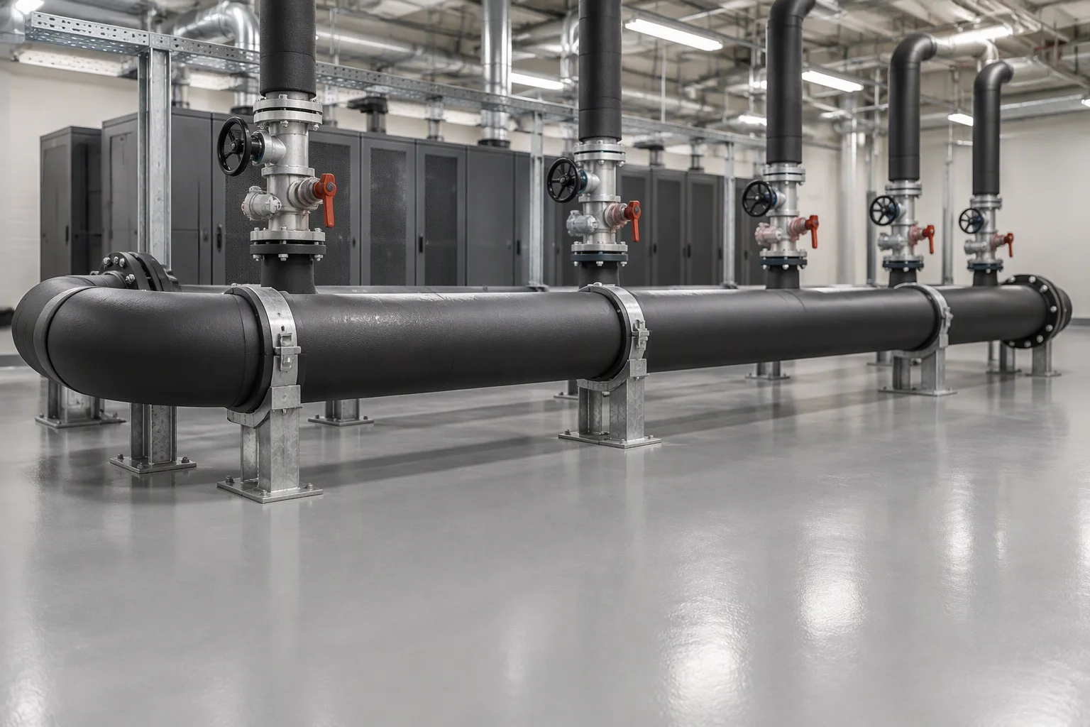
Profile B · ring main with branch take-offs
The main returns to itself, so a branch can be isolated without stopping the ring. Every take-off is a pair of joints that the coolant passes twice.
Working 1.38 MPa ≈ 200 psiBurst ≥ 5.5 MPa
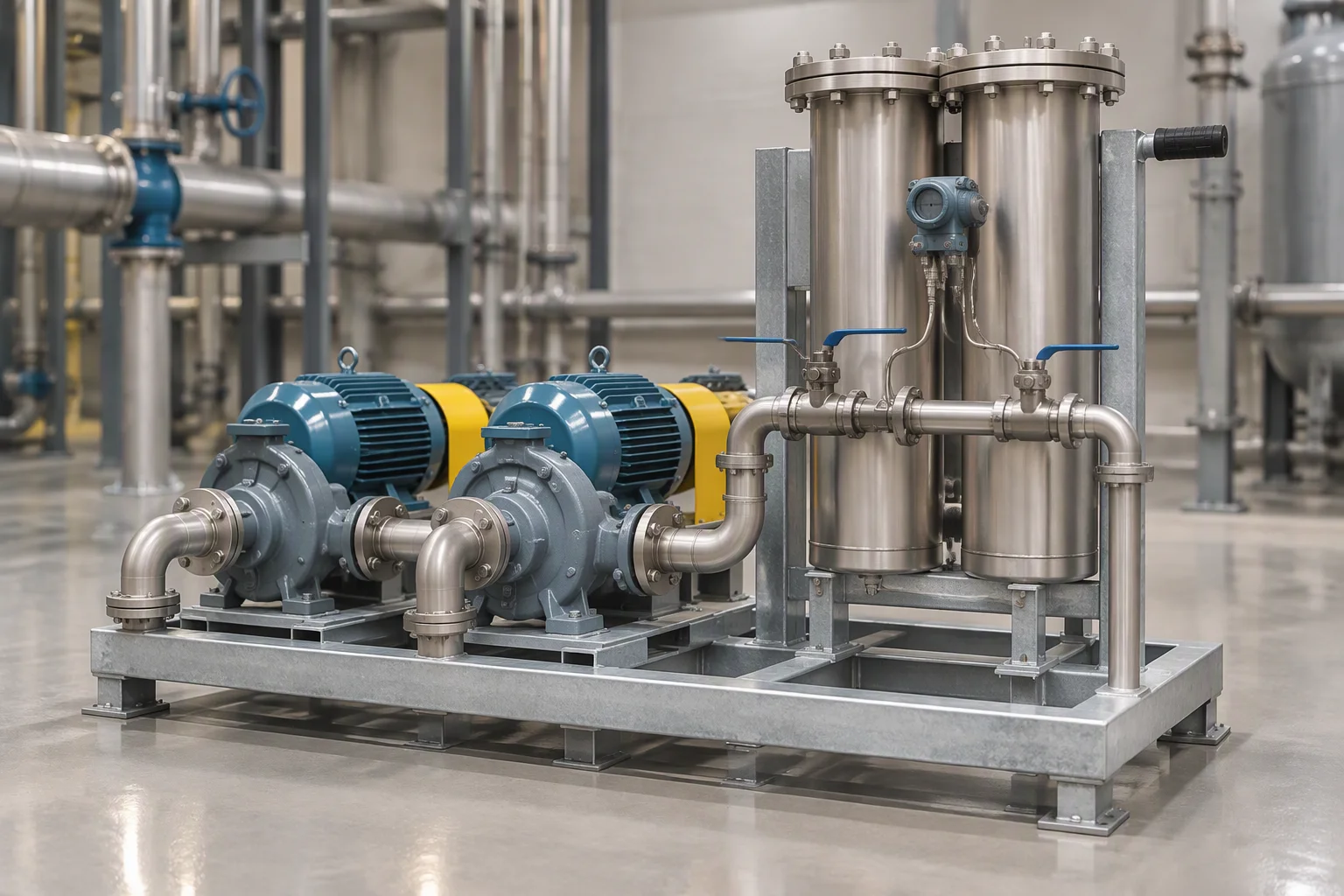
Profile C · twin pump set with a filtration branch
The pumps run duty and standby and the filter sits on a bypass branch, so the element can be changed with the loop still circulating.
Filtration 1 µm absoluteGrades 0.05–100 µm
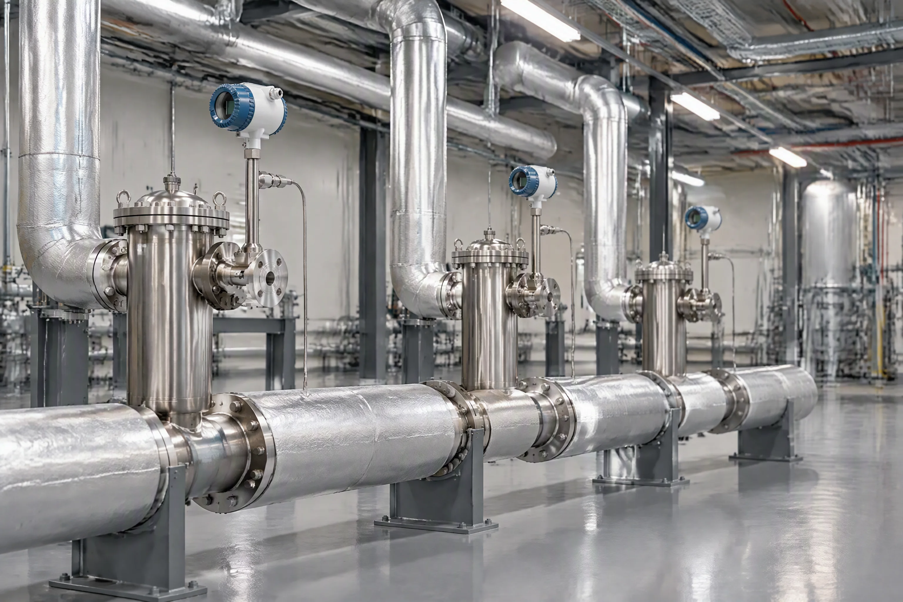
Where the profiles part company is the take-off, not the coolant. The filter and the transmitter sit at the change-over on every one of them.
Read next · Hose & piping · Quick disconnects · Coolant filtration
The consumables each profile carries
The parts below are the ones a loop consumes: it does not burn them, it loads filters and it wears seals. A profile is quoted from the number of joints, the bore it runs at, the filtration grade it holds and the length of sensing rope it needs to cover the floor void under it.
The filter element is the only part on the loop that turns into a contaminant source as it works.
Every quick disconnect is a seal pair, so the joint count is the risk count.
| Profile | Consumables on the loop | Chosen on | Document held |
|---|---|---|---|
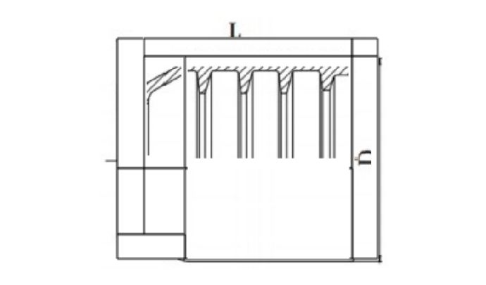
| A · row supply and return | EPDM hose drops, quick disconnects at each end, point sensors under the manifolds | Bore 6.1–15.8 mm; one seal pair per rack in each direction | Outline drawings |
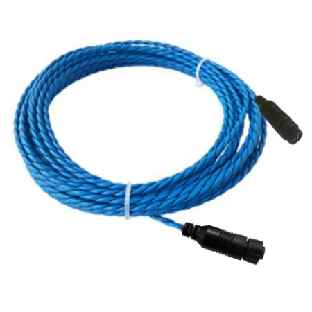
| B · ring main with take-offs | Ring pipework, isolating valve pairs, locating sensing rope in the floor void | Working 1.38 MPa ≈ 200 psi, burst ≥ 5.5 MPa, sensing to 500 m per channel | Hydrostatic and burst test report |
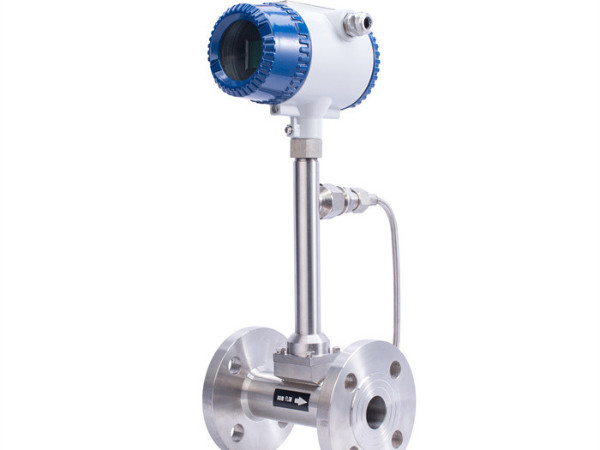
| C · twin pump with filtration branch | Filter housings and elements, differential pressure transmitter, level sensor on the reservoir | 1 µm absolute, changed out at 0.5–0.7 bar | Specification sheet |
Read next · Filter cartridges · Locating sensing rope · Retrofit notes
What changes when a loop is extended or rebuilt
A loop is rarely built once. A row is added, a rack density goes up, a filtration branch is inserted behind a pump set. The hardware that changes is almost always the same short list, and the cost of the change is decided by whether the loop can stay closed while it happens.
The four notes below are the ones that come back on every rebuild. They are written for the contractor holding the loop: the tie-in point, the branch that can be isolated, the torque on a reused seal face, and the sampling point that proves the coolant is still inside its cleanliness band afterwards.
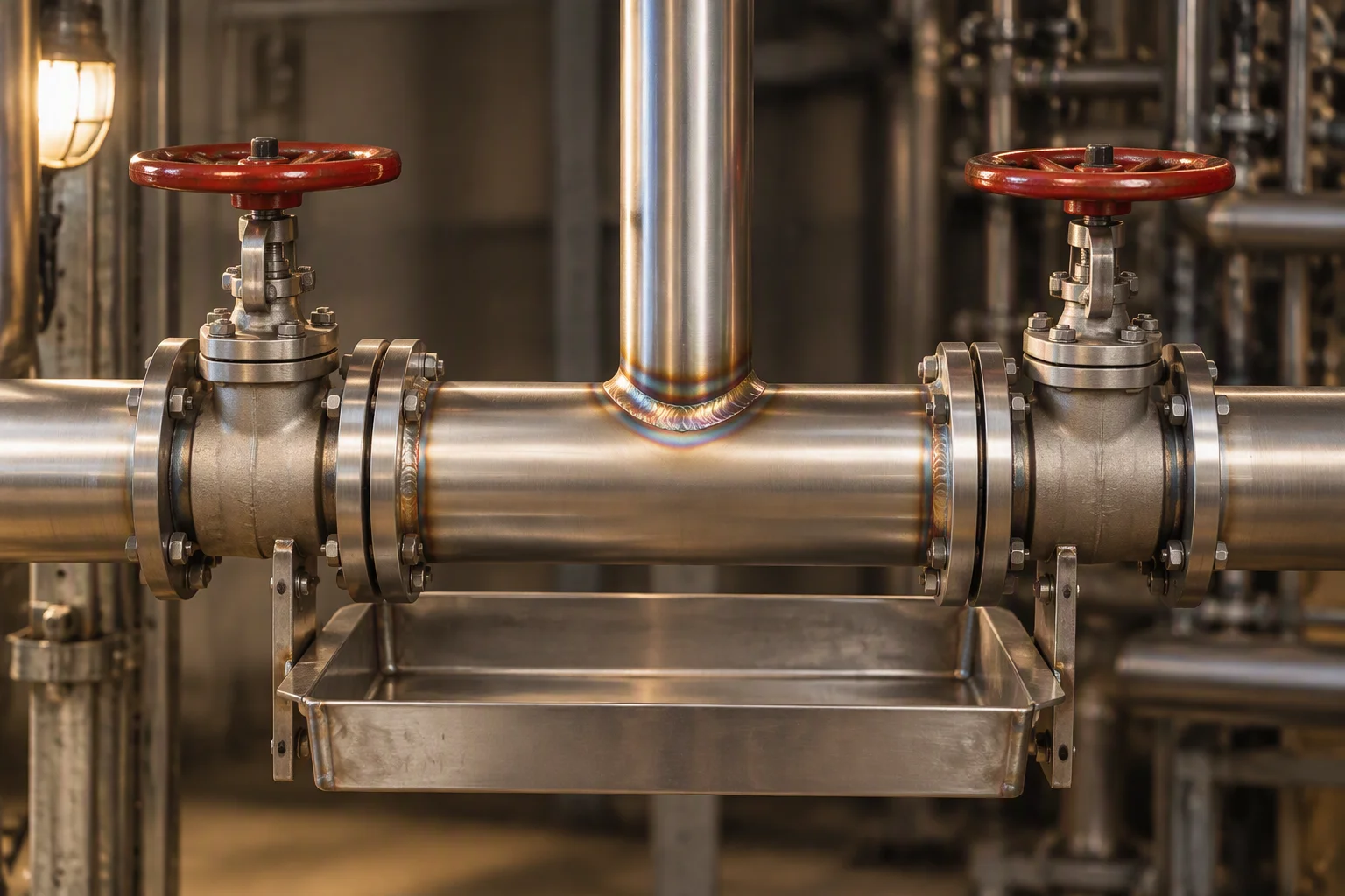
The tie-in is a tee on the header, not another drop at the rack.
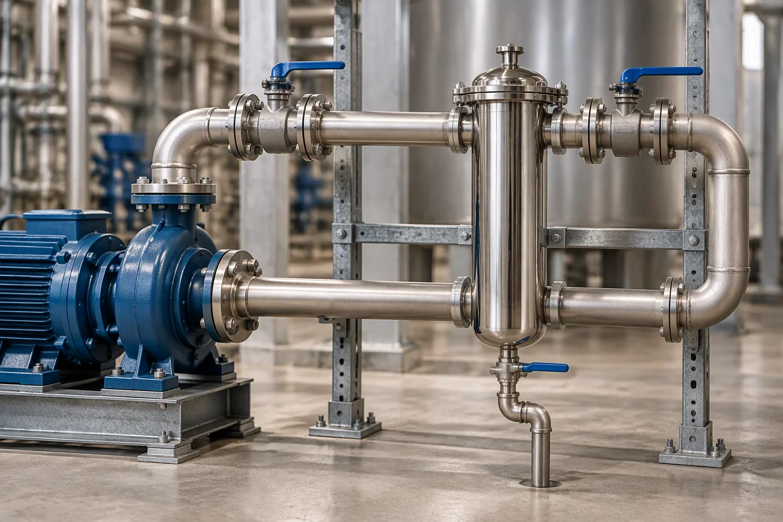
A bypass branch lets the element come out with the loop still circulating.
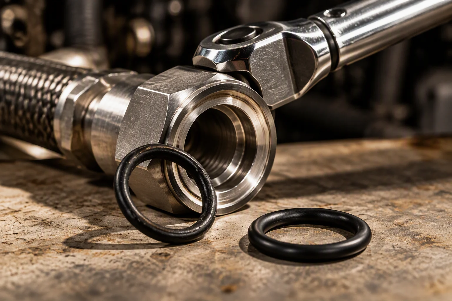
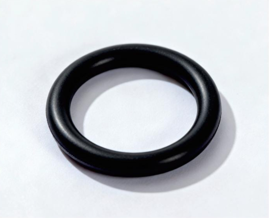
A reopened joint takes a new ring. The old one has already taken its set.
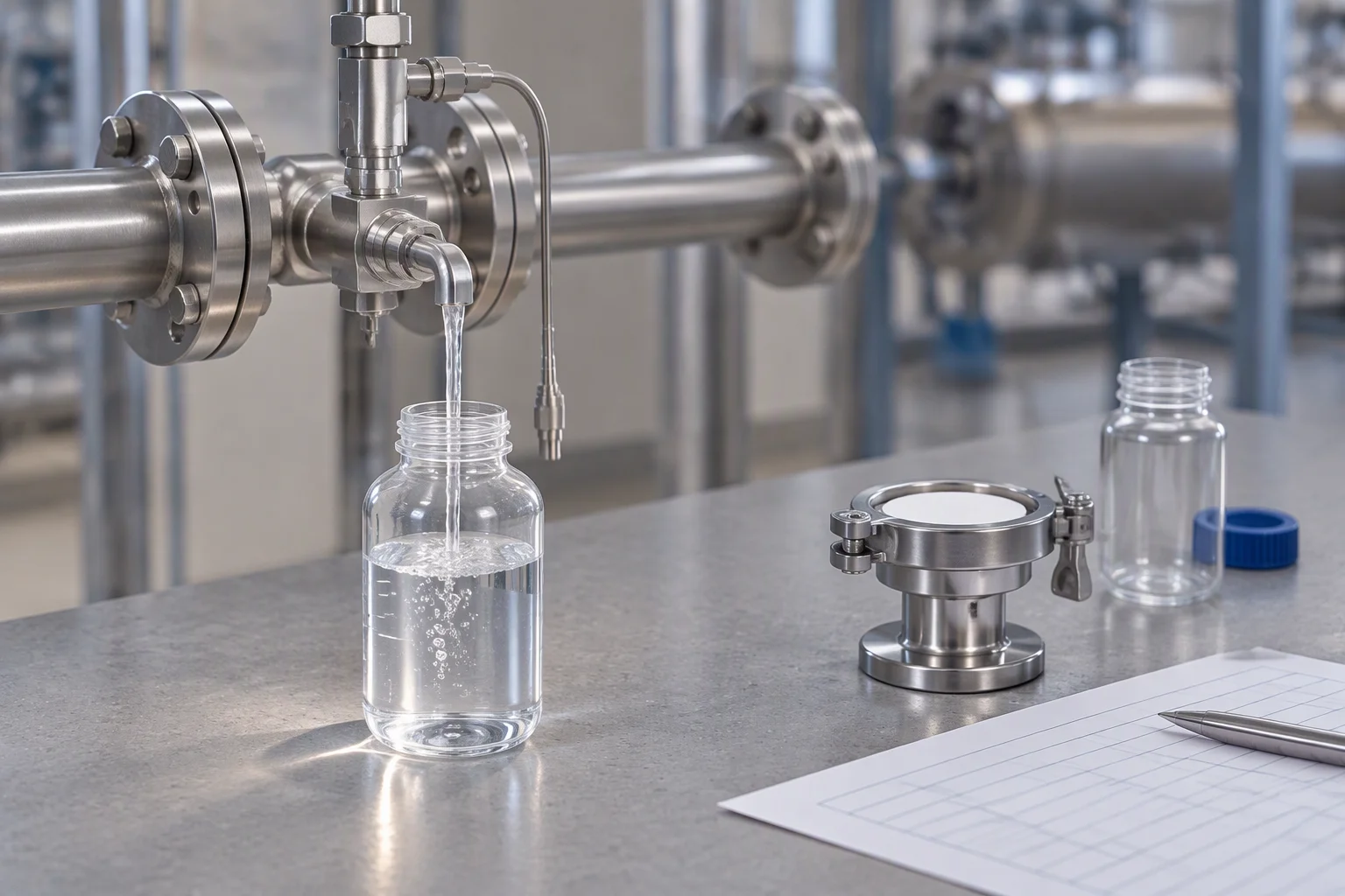
The sample is what puts the new branch back inside the cleanliness band.
A profile on this sheet describes the loop, not the building. It carries no customer name, no site name and no installed quantity, and it is not a drawing of any particular room.
Read next · Commissioning · Fittings and seals · Quality & inspection
Four documents are held for this sheet. Tick the ones you need.
Tick a document, name the loop and the profile it is closest to, and the file comes back attached.
One business day, with the file attached.
Nothing else on this sheet is promised. Price, stock and lead time are not promised here.
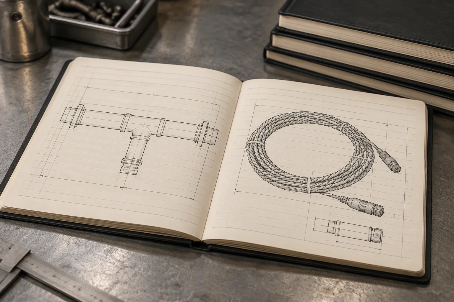
The sheet is held per profile, at its current revision.
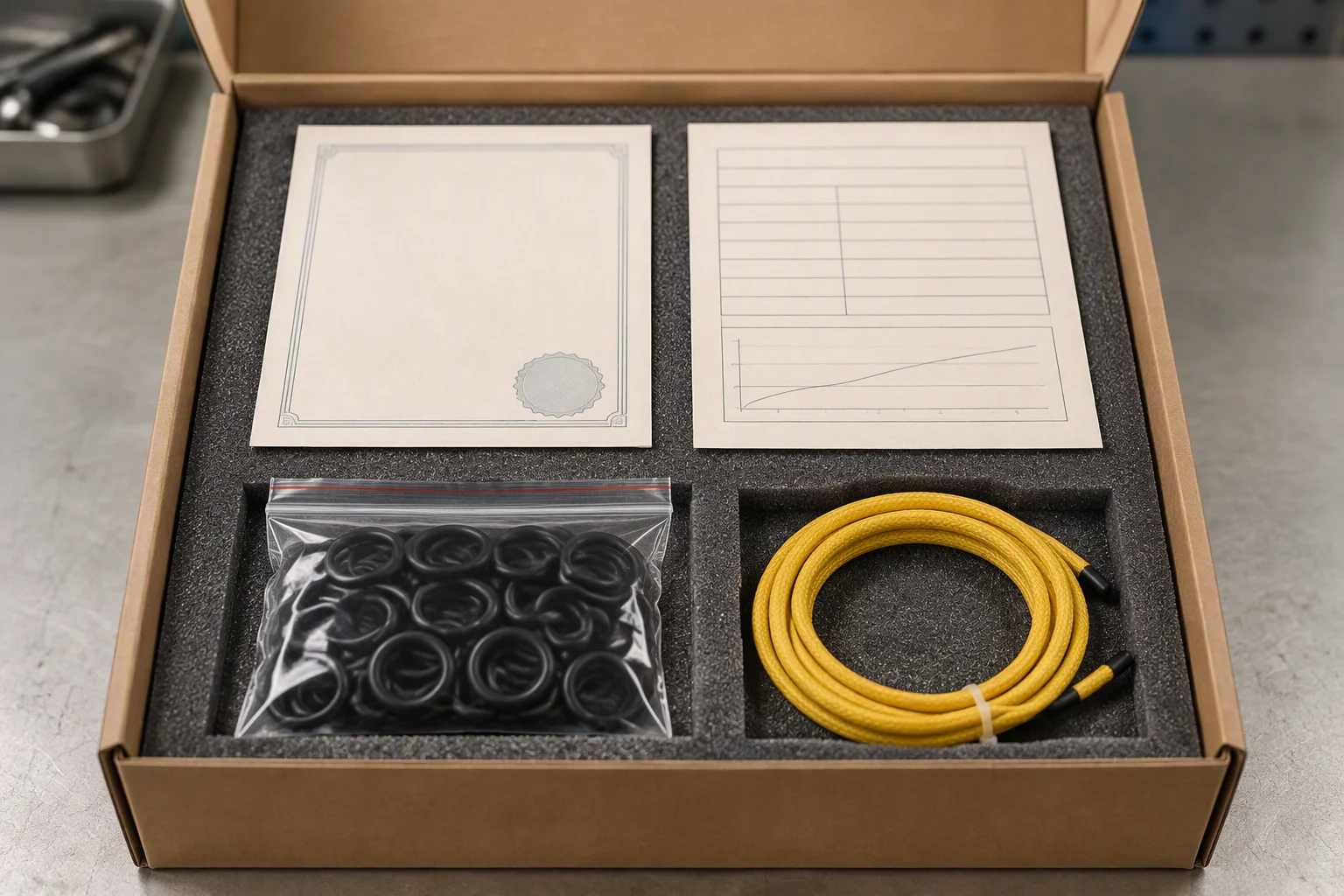
Certificate and report travel in the carton, not in a later email.
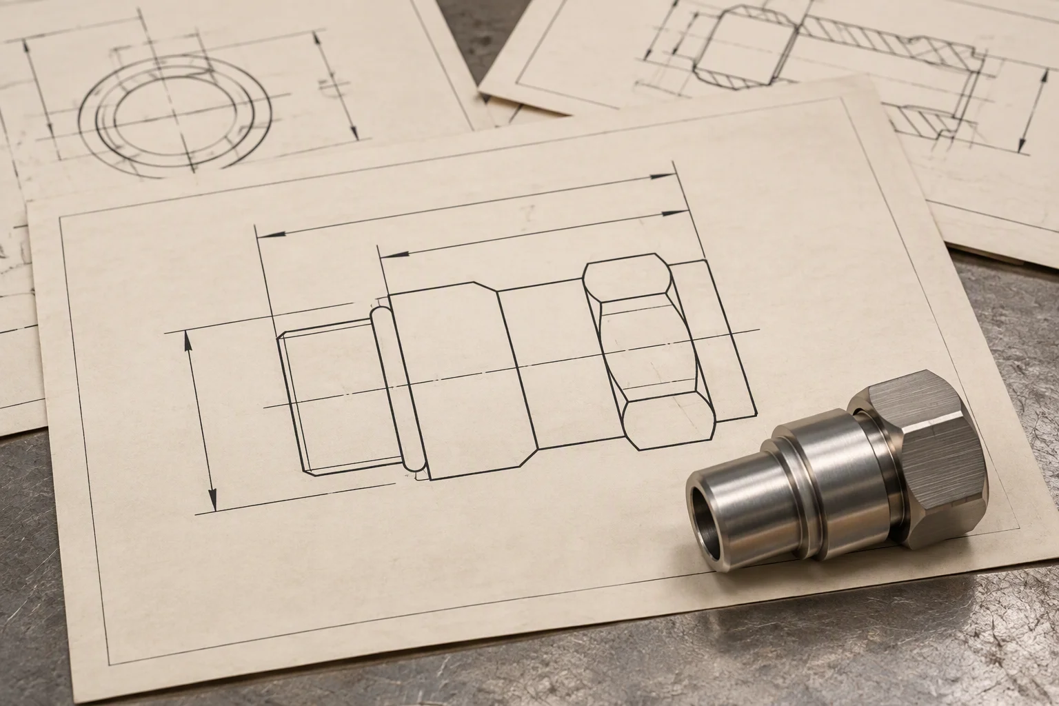
The joint schedule is the page a quotation is checked against.
