
Leak detection for the liquid cooling loop
Locating rope, point sensors and the controller that report a wet joint to the BMS.
The leak is found below the floor. The round is above it.
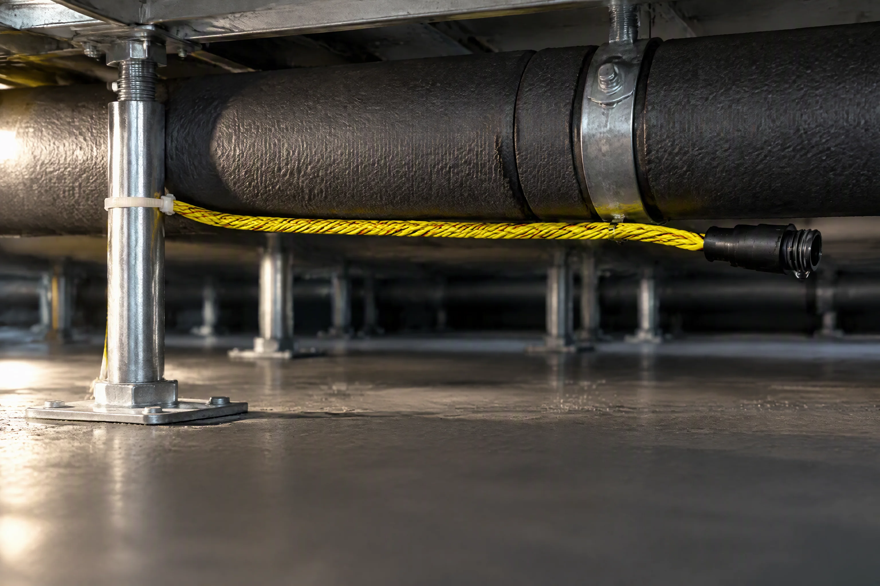
The loop runs under the raised floor, through joints nobody lifts a tile to inspect. A weep there reaches no ceiling sensor and shows on no walk-round. It reaches the slab, spreads sideways, and the first visible sign is a wet tile rows away.
Three devices close that gap: a locating rope for distance, point sensors for a drip tray, and a controller that turns either one into an address on the building management system.
Scope of this line: the loop and its sensing. We do not supply the CDU, and we do not supply the cold plate.

Above the floor: the aisle a round walks, trays overhead, and a slab that hides everything under it.
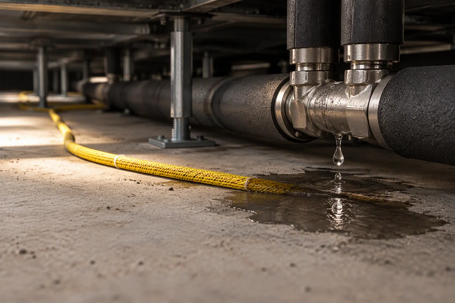
Below it: the rope is laid where the coolant arrives, not where the round passes. On the slab, beside the pipe.
A rope for distance, a point sensor for one drip tray
Two braided electrodes under a woven jacket. Water changes the impedance between them, and the controller times the round trip to that change: a position along the run, to 0.1 m.
A point sensor does the same work in one place: a drip tray, a valve gland, a pump seal. It is a dry contact device, so a channel takes either without a change at the panel.
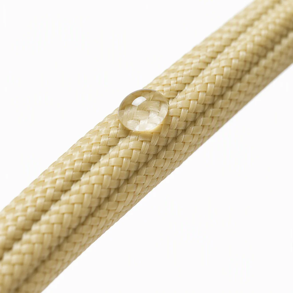
Two electrodes, one jacket. Water between them is the measurement.
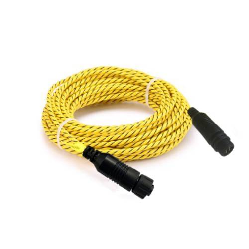
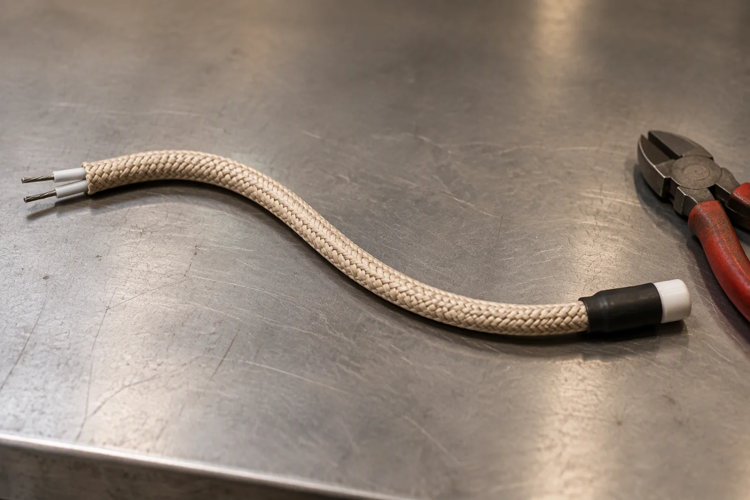
Cut to the run, both ends terminated before the rope leaves the reel.
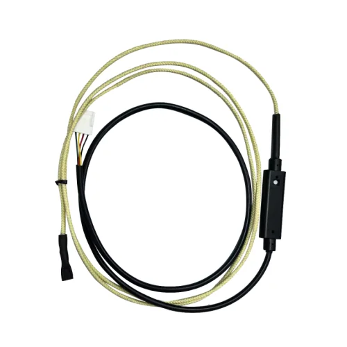
Sensing run with an in-line module: the same rope, one addressable place.
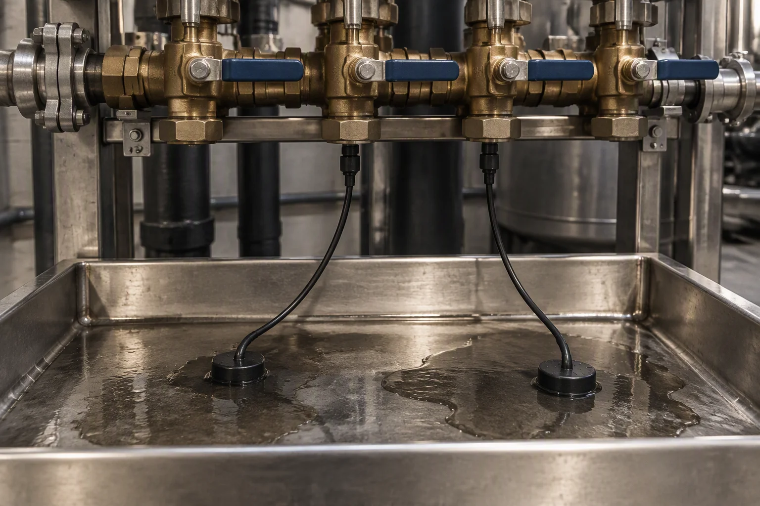
A drip tray under a manifold, where a gland drips into steel rather than onto the slab.
Read next · Locating sensing rope · Point sensors
One controller carries the channels and the reporting
A wall unit with 4, 8 or 16 channel terminals. Each channel takes one rope run or one point sensor, and carries its own address.
It reports over Modbus RTU, a dry contact relay or a 4–20 mA loop, whichever the site already runs. A wireless gateway carries that report where no cable can be run.
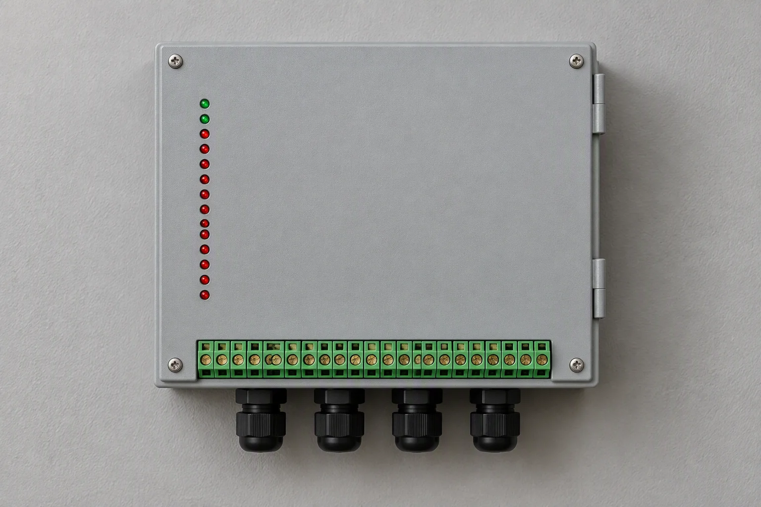
Sixteen channels in one enclosure: a pair of terminals per rope run or point sensor.
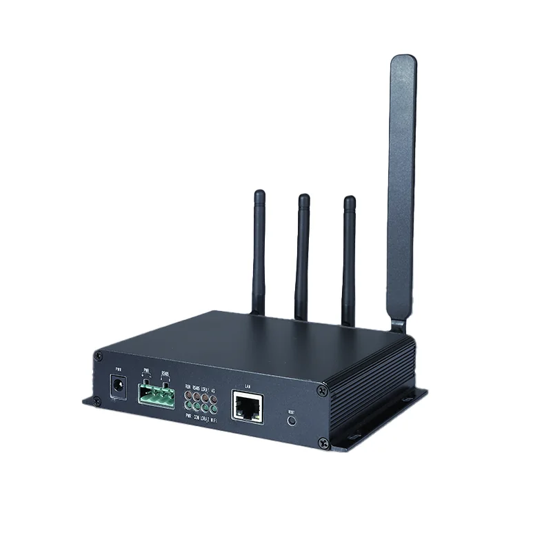
For sites with no spare pair to the BMS: RS485 in, wireless out.
Where a run ends short of the panel, a lead cable closes the gap. Accessories are cut and terminated to the run.
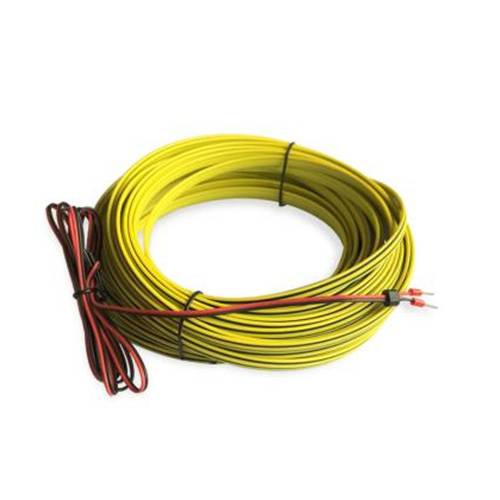
Lead cable, ferrules fitted.
Termination lead for the end of a run.
Read next · Controllers · Accessories
One channel is one pair of terminals
The rope or the point sensor lands on a pair of terminals. The shield goes to the same earth as the panel, and the far end of a run closes at an end termination. Three paths leave the controller.
Key
- 01Rope channel: one pair of terminals, one run, up to 500 m.
- 02Point sensor on the same pair of terminals.
- 03End termination closes the far end of a run.
- 04The report leaves over one of three paths.
Sensing on the left, reporting on the right. One pair of terminals per channel.
Modbus RTU: two wires on RS485, address set at the panel.
Dry contact: a volt-free relay for a local alarm or a PLC.
4–20 mA: an analogue loop for a current input.
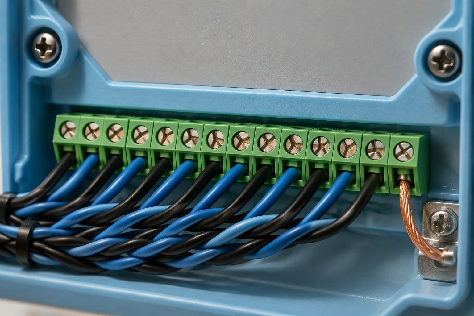
Terminals landed and numbered, one pair per channel.
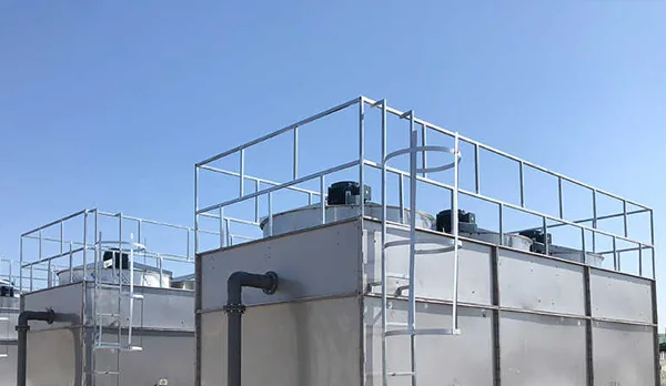
The loop does not stop at the hall: plant decks carry the same joints.
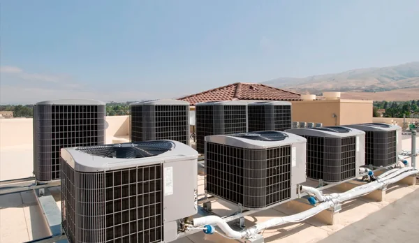
One channel can cover the deck and report its position.
Read next · Telemetry instruments · Design guides
Choosing a channel count
Count the areas you want addressed separately, not the metres of pipe. Two aisles and a plant room are three areas, and every channel covers up to 500 m of rope or one point sensor.
Two aisles and a plant room: three areas on a 4 channel controller.
| Channels | Areas addressed | Detection length | Where it fits |
|---|---|---|---|
| 4 channels | up to 4 areas | 500 m per channel | One hall, or a hall with its own plant room |
| 8 channels | up to 8 areas | 500 m per channel | Two halls, or one hall with separate aisles |
| 16 channels | up to 16 areas | 500 m per channel | Multi-hall sites and phased fit-out |
Two aisles on one channel report one wet tile between them. Two aisles on two channels name which one.
Monitored areas · server halls · aisles · CDU connections · plant rooms · battery rooms · UPS rooms · chiller supply and return
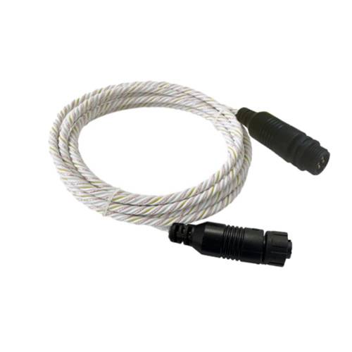
Rope is cut to the area: the run length follows the count of channels you chose.
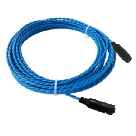
One channel, one long area: 500 m of detection.
One channel, one short area: cable cut at the bench.
Read next · Design guides · Industries
Request the specification file
Four documents are held for this line. One request returns them attached, next business day.
- Specification sheet rope, sensors, controller
- EN 10204 3.1 material certificates metal parts
- Test report on request
- Outline drawings controller and end terminations
One business day, with the file attached.
No other commitment is made on this sheet. Price, stock and lead time are not promised here.
If the form cannot send, this address takes the request instead: sales@ems-cool.com
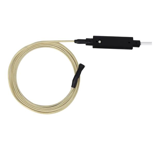
Sensing rope with its detector module, terminated before packing.
Rope set with both ends terminated.
