>
Telemetry and instruments

CDU telemetry for liquid cooling loops

A loop's supply-to-return difference is only 5–10 °F. Two unmatched sensors at ±1 °F each put almost 50 % uncertainty on it, so capacity cannot be verified.

Ask for the specification sheet

One matched pair, one part number.
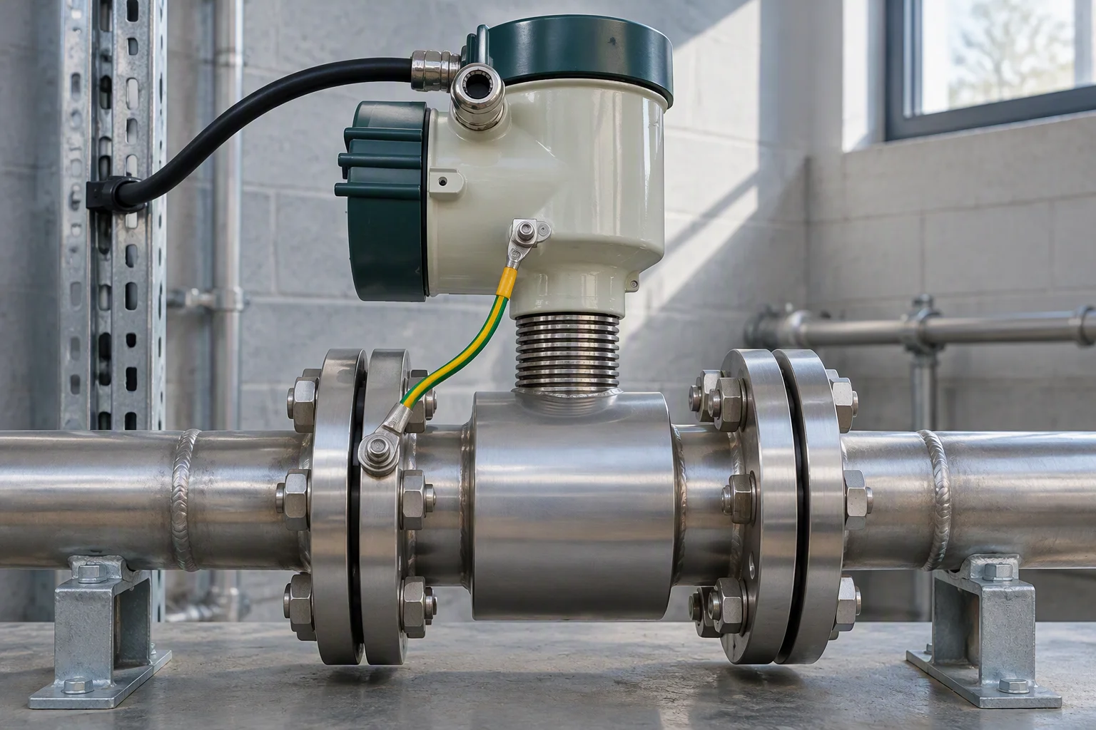
A single electromagnetic flow meter flanged into a short run of stainless header on a bench, with a grounding strap bonded to its body and a cable gland on top
  • The kitFour codes by loop class Open
  • Sensors and gatewaysSeven sensors, three gateways Open
  • Leak detectionRopes, probes, controllers Open
  • Coolant filtrationElements the filter channel reads Open
Parameter map

Five parameters, four instrument classes

Parameter, instrument, value.
ParameterInstrumentValue
TemperatureMatched resistance pair, IEC 60751 Class A−40 to +150 °C
FlowElectromagnetic, or ultrasonic under the floorDN25 0.5–18 m³/h, ≈36:1 turndown
Differential pressureTransmitter, 100 kPa filter or 400 kPa loop±0.075 % FS
Liquid levelOptical point switch or hydrostatic analogueCable 0–75 °C
LeakRope channel, 2-wire detects, 4-wire locatesFluid reaches the sensor
Flow principle

Pick the flow principle for the fluid

Conductivity axis, 0.1 to 100 microsiemens per centimetre A log conductivity axis: shaded technology-cooling band, dashed meter floor, bracket under the floor.
Loop type beside every number.
De-ionised technology cooling0.2–20 µS/cm
Glycol premix or facility water50–300 µS/cm
Electromagnetic floor5 µS/cm
Below the floorNear zero, no fault
Installation geometry

Straight runs are part of the accuracy budget

Specified runs are 5× DN upstream and 3× DN downstream. Without them error rises about 1.5 % of reading, three times a ±0.5 % of reading claim.

Meter plan view with five times DN upstream and three times DN downstream runs A pipe in section with flanges, the meter body between the middle pair, the upstream run dimensioned wider than the downstream one.
Point map

What the gateway has to absorb

Gateway point map: field layer, edge gateway, head end Field instruments concentrate onto an edge gateway at ten points, which reaches the head end over one RS-485 trunk and two Ethernet ports.
  • Fluid Flow Rate
  • Inlet Fluid Pressure
  • Outlet Fluid Pressure
  • Differential Pressure
  • Fluid Loop High/Low Differential Pressure

Ten-point controller: 5 universal inputs, 2 analog outputs, 3 triac outputs, 1 RS-485, 2 Ethernet, expandable to 50 points.

Alarm logic

Two-of-two, so a sensor earns its alarm

Mechanism, and the mitigation.
Alarm floodingTwo-of-two logic
Too many nuisance alarmsRedundant, cross-checked sensors under a two-of-two rule
Operators learn to ignore itEither the tray sensor or the manifold rope detects, and the channel alarms
Condensation reads as a leakBoth detect, and intervention is permitted

Supply water stays 2 °C (3.6 °F) above dew point.

Boundary

Where the instrumentation stops

Nothing above the loop

No coolant distribution units, no cold plates.

One verifiable claim

The loop delivered the flow and ΔT it was designed for.

Flow the kit must read

Rack TCS 10–100 L/min against facility 140 L/min.

A rack CDU secondary holds 5.7 L against 3.4 L primary. Fill and flush runs through fill and flush; commissioning through technical resources.

Model index, 14 codes

Sensors and gateways
  • EMS-TL-K100 Single rack to 100 kW PDF
  • EMS-TL-K300 Row 100–300 kW PDF
  • EMS-TL-K800 Row to 800 kW PDF
  • EMS-TL-K2300 Room 2.3 MW PDF
  • EMS-TL-ST Matched pair, thermowell PDF
  • EMS-TL-STC Matched clamp-on pair PDF
  • EMS-TL-SF Electromagnetic flow PDF
  • EMS-TL-SFU Ultrasonic flow PDF
  • EMS-TL-SDP DP transmitter PDF
  • EMS-TL-SL Liquid level PDF
  • EMS-TL-SK Leak channel module PDF
  • EMS-TL-G10 Gateway, 10 points PDF
  • EMS-TL-G25 Gateway, 25 points PDF
  • EMS-TL-G50 Gateway, 50 points PDF

Every code carries 10 or more parameter rows.

Specification request

Ask for the specification sheet

Leave your work email and the model code. One datasheet per model, with position resolution and locating repeatability stated as separate rows.

  • A specification table of at least ten rows per product family, and a downloadable PDF for every model listed.
  • Seal-life data where it decides the choice: permeation rate, compression set and fluid compatibility.
  • One working day for a reply, from an engineer rather than a catalogue autoresponder.
Reply within one working day