
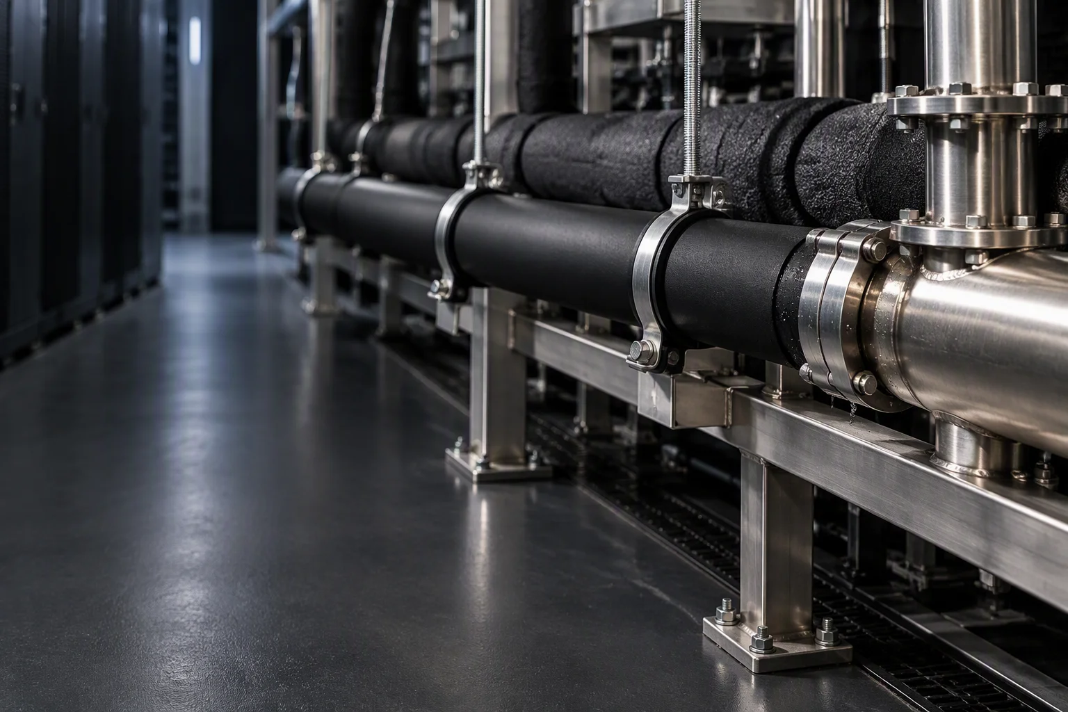
Hose and piping for the liquid cooling loop
EPDM hose, the fittings at each end, and the couplings that let a rack come out without draining the run.
Three layers decide how long the hose lasts
A tube carries the coolant, one or two layers of synthetic fibre braid hold the pressure over it, and a cover keeps ozone and UV off the braid. Each layer fails on its own: the tube hardens, the braid chafes at a clamp, the cover cracks.
The line is quoted to −40 ~ +99 °C for data centre duty. The same construction is tested by the supplier to +120 °C, which is the margin the cover has to hold.
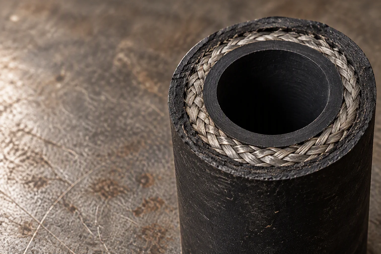
Cut one hose and the wall reads as three rings. The braid is what the 1.38 MPa working pressure is quoted against.
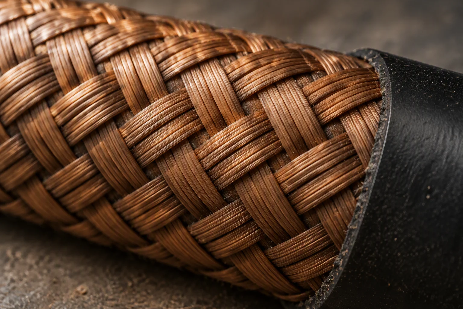
Layer 02. One braid carries the working pressure; a second is what raises the burst figure.
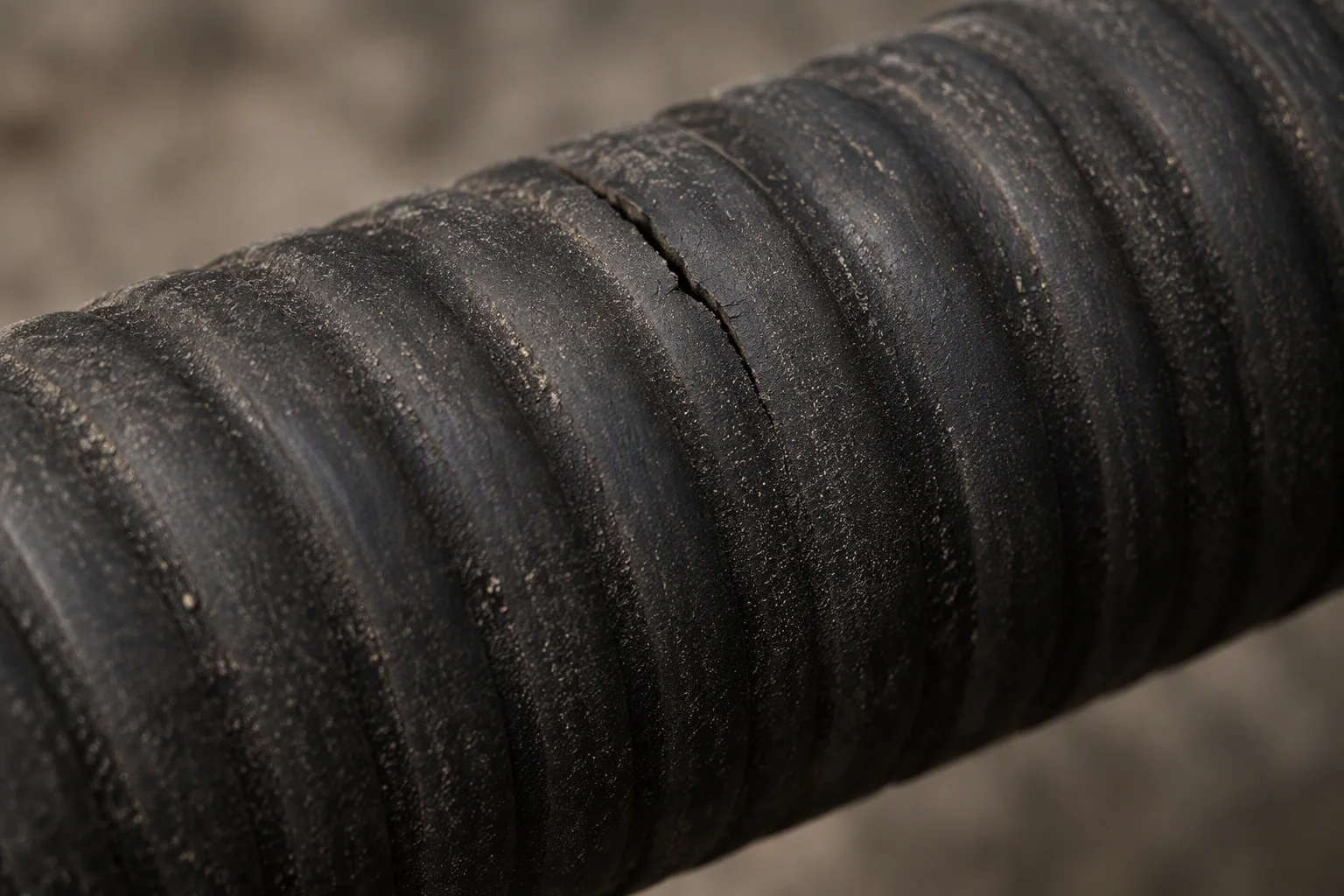
Layer 03. The cover is a flame barrier rated UL 94 V-0, and the first thing a cable tray rubs through.
What this line is quoted on
| No | Boundary | Value | Unit | Note |
|---|---|---|---|---|
| 01 | Working pressure W.P | 1.38 | MPa | About 200 psi, on DASH −4, −5 and −6 |
| 02 | Minimum burst B.P | 5.5 | MPa | Minimum, on the finished assembly |
| 03 | Coolant temperature data centre claim | −40 ~ +99 | °C | Supplier tests the same wall to +120 °C |
| 04 | Bore I.D | 6.1 – 15.8 | mm | Across DASH −4 to −10 |
| 05 | Minimum bend radius B.R | 24.5 – 69 | mm | Tracks the bore, not the cover |
| 06 | Weight per metre | 0.13 – 0.25 | kg/m | Hose only, dry, before fittings |
| 07 | Reinforcement braid layers | 1 – 2 | layers | Synthetic fibre over the tube |
| 08 | Cover flame rating | UL 94 V-0 | , | On the outer cover |
| 09 | Group standard EPDM hose | T/CAEE 085—2026 | , | Written around water-based coolant |
| 10 | Material certificate metal parts | EN 10204 3.1 | , | Covers the fittings, not the rubber |
The schedule above is the envelope the line is sold inside. A grade data sheet carries the same rows for the single DASH size you order.
Quoted against · OCP Cold Plate Coolant Base Spec v1.3 · ASHRAE W17–W45 supply temperature classes · ISO 4406 17/15/12 cleanliness target
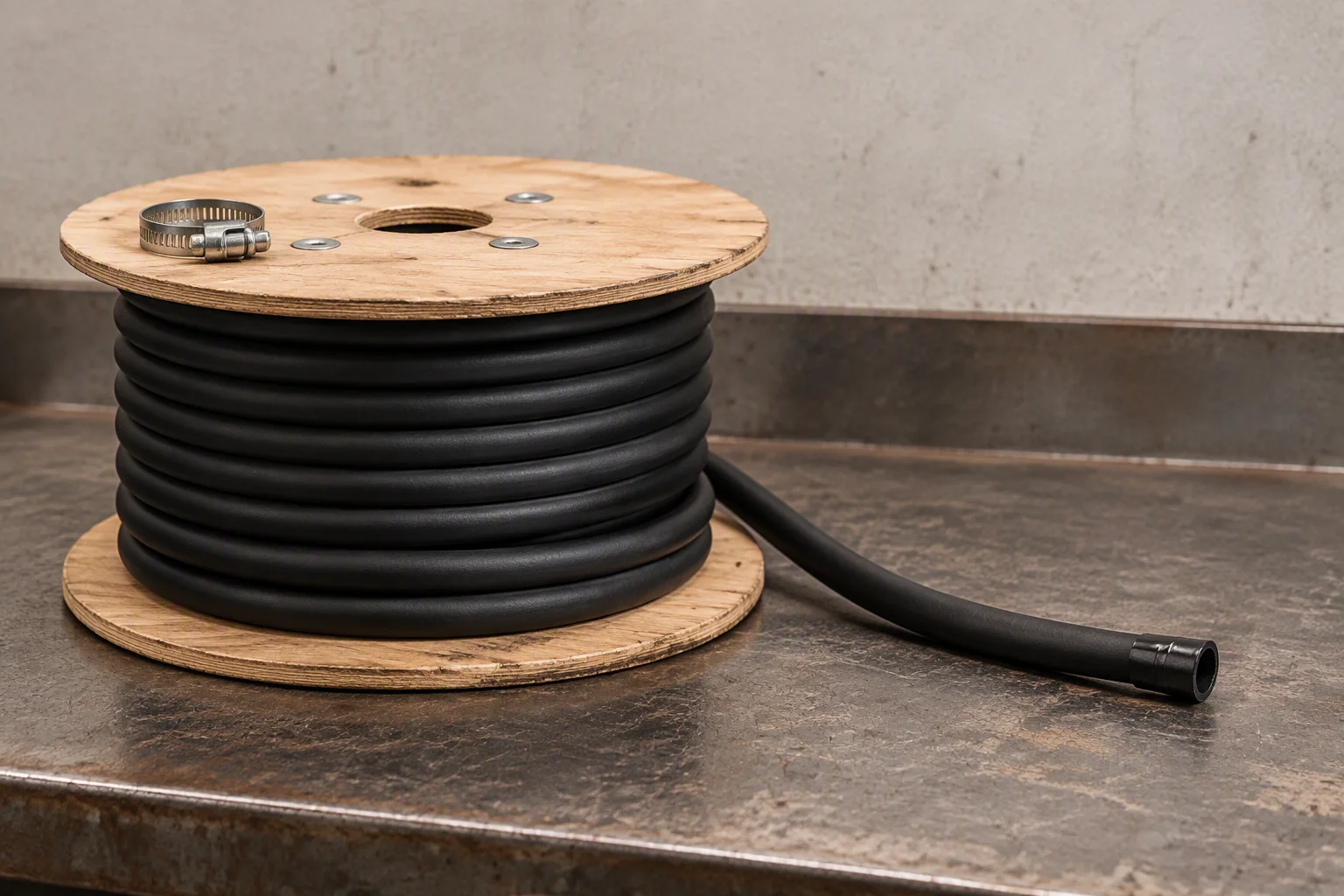
Coiled on a reel, cut to the run.
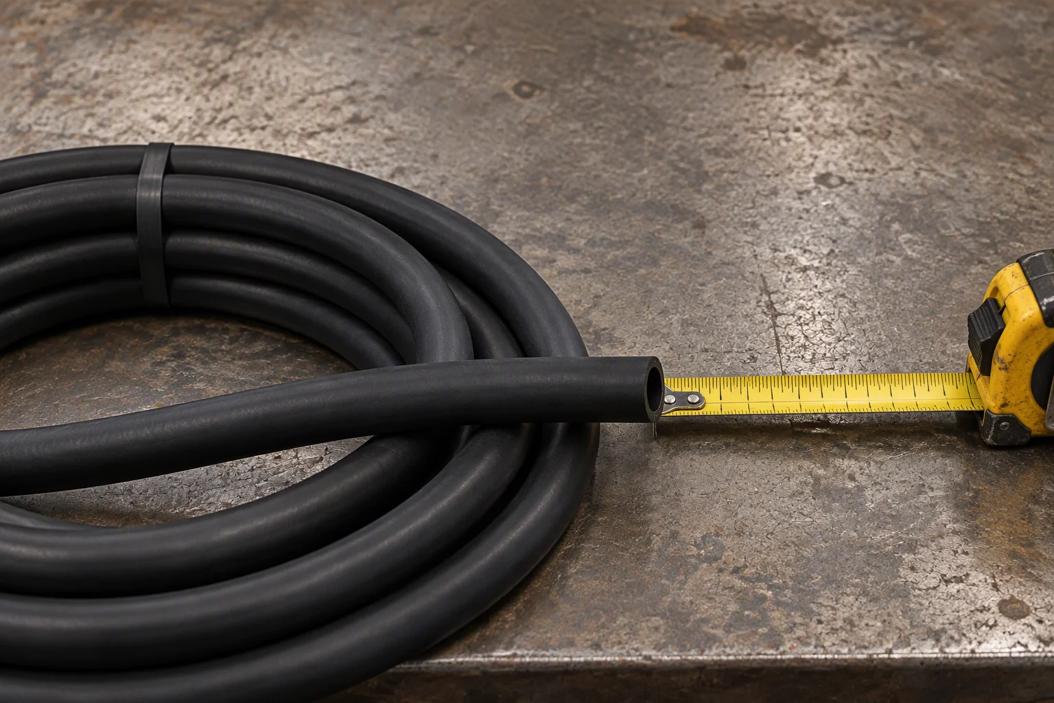
Length is cut to the drawing, not to the next whole metre.
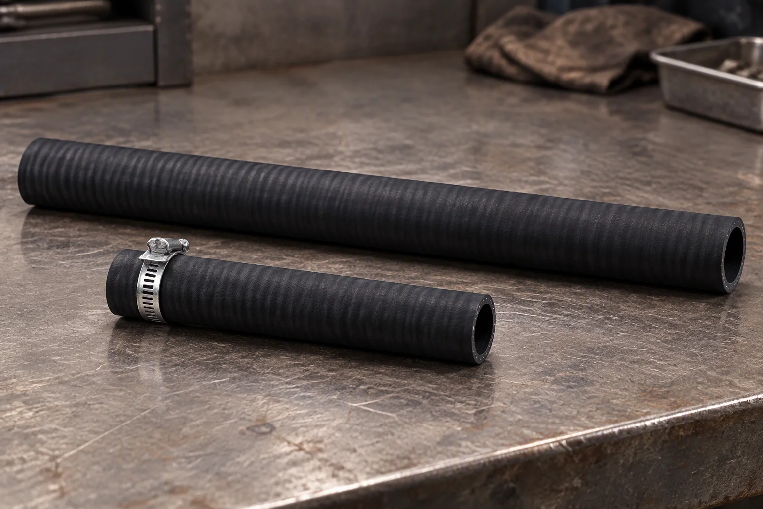
Custom lengths from 500 m, one carton on standard sizes.
A joint is a seal face, not a thread
Two threads hold a fitting in place. What stops the coolant is the face between them, and the elastomer compressed there. A straight adapter, a 90° elbow and a hose tail all end in the same two questions: which face, and how much preload.
Seals are the part of a loop that ages without moving. Ethylene propylene diene monomer takes water-based coolant and glycol mixes, and it is the same elastomer the hose tube is made of.
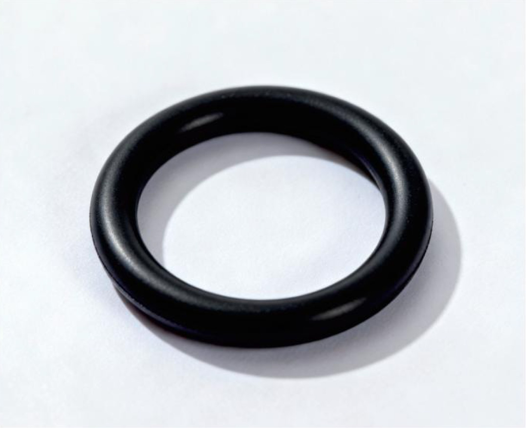
One ring, one face. The section is what is quoted, not the outside diameter.
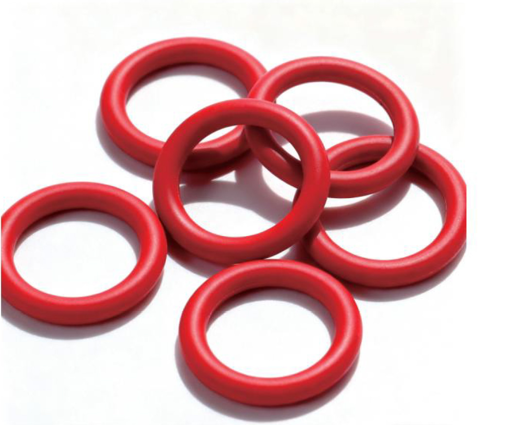
A set by size. Each ring is bagged against the fitting it was cut for.
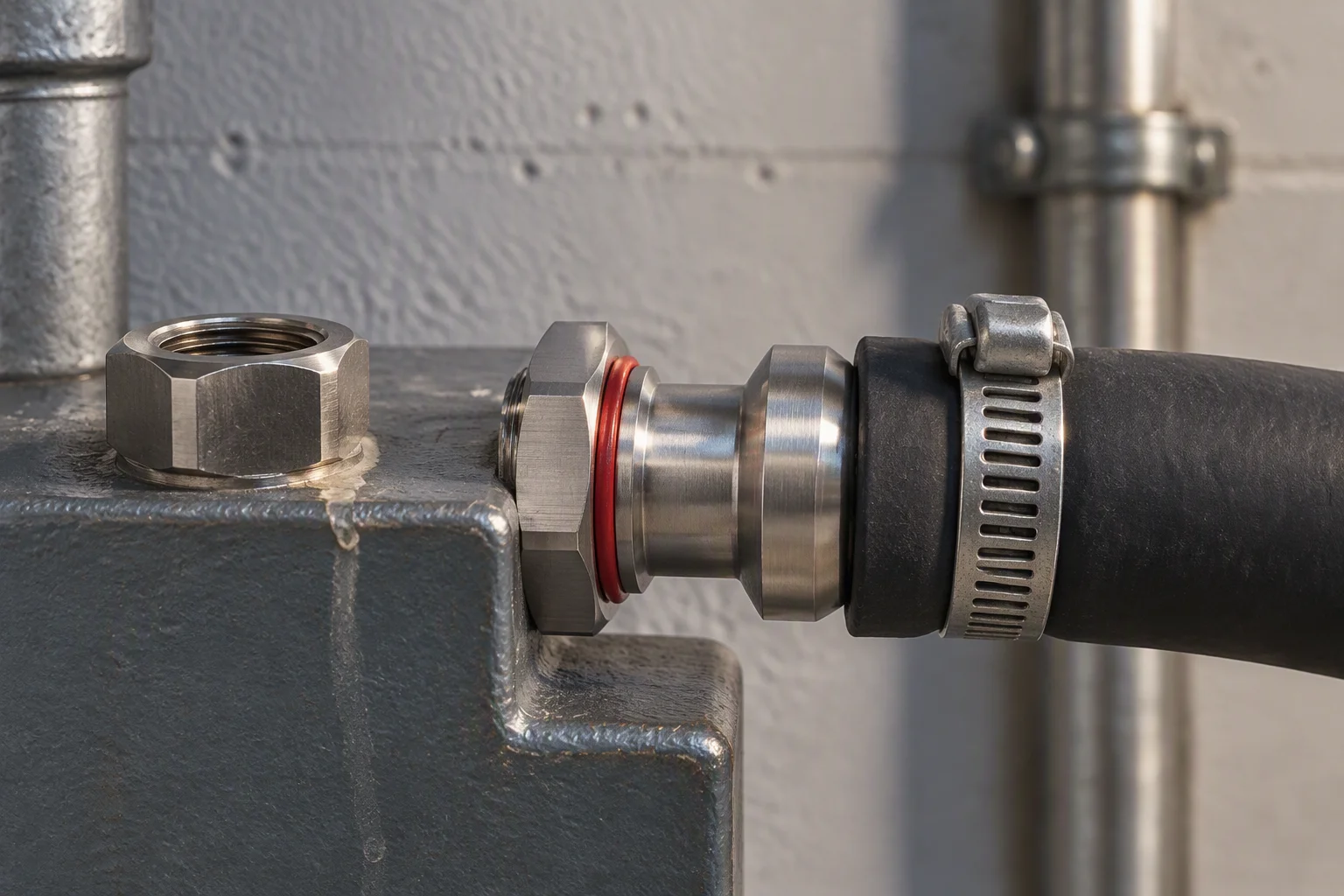
The tail goes into the hose, the hex goes into the port, and the ring sits between them.
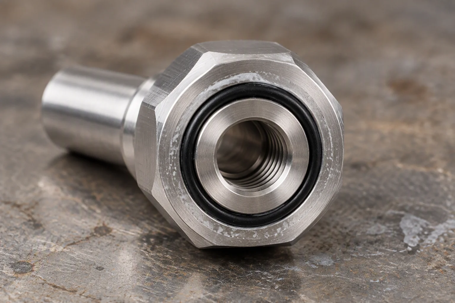
A sealing land with a ring in it. Coolant tracks past the land before it reaches the thread.
Read next · Fittings and seals · Seal degradation mechanisms
The coupling is where the loop gets opened
Every rack swap opens a joint. A universal quick disconnect makes that a one-handed action with a drip tray under it, instead of a drain-down. The figure that matters is not the flow rate: it is how many times the coupling can be opened before the seal face marks.
A quick disconnect is two halves, one seal face each, and a sleeve that has to travel before anything separates.
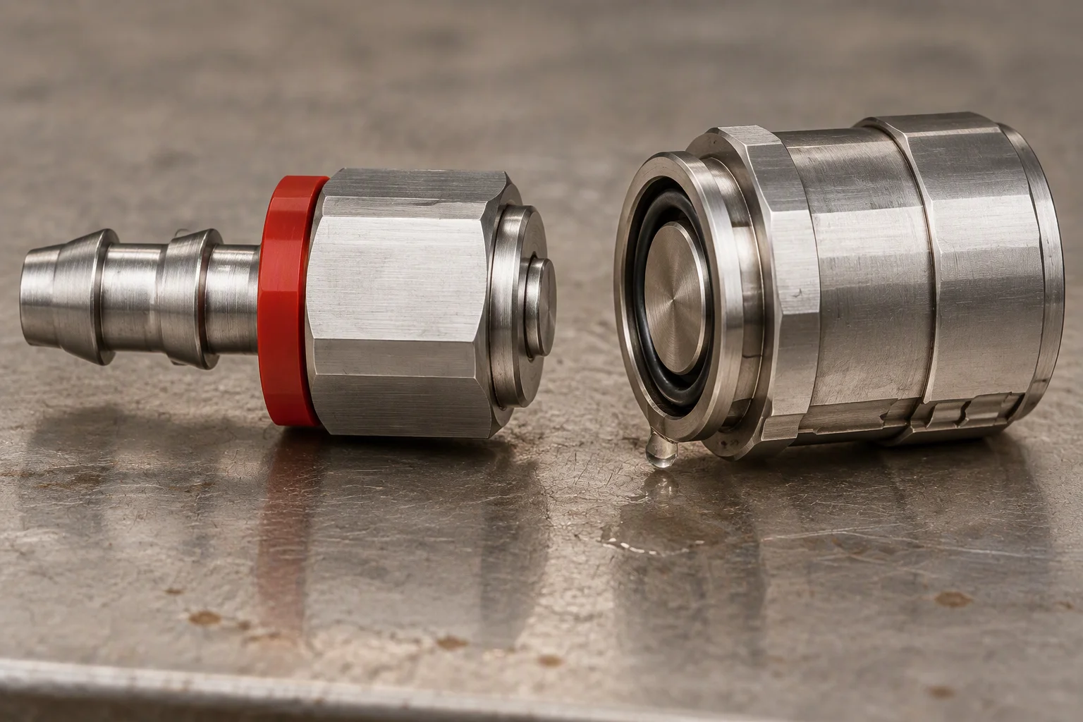
Two halves, two faces. Both halves close on the way out, so the run stays wet.
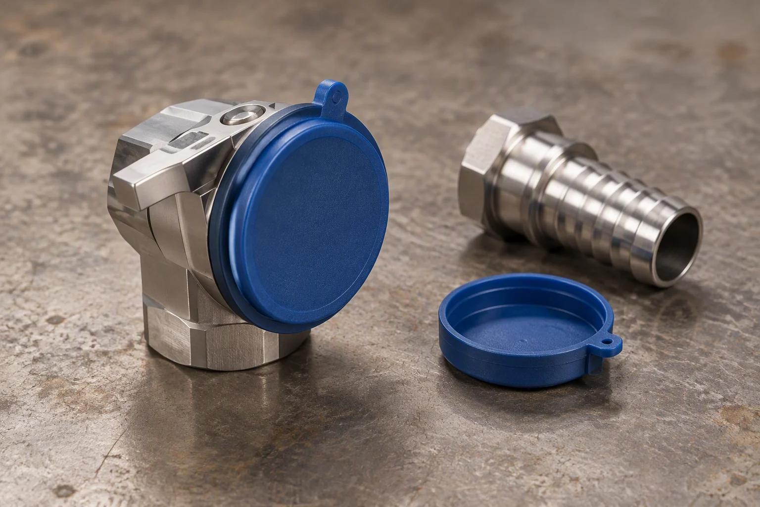
Opened and capped. A dry half collects dust on the face it has to seal against.

Rack end. The tray below it catches the drop a tired ring leaves.
Read next · Quick disconnects · Quick disconnect duty cycles
Request the specification file
Four documents are held for this line. Tick what you need and the set comes back attached.
One business day, with the file attached.
Nothing else on this sheet is promised. Price, stock and lead time are quoted against a request.
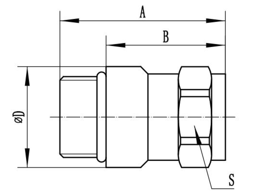
Outline drawing. Lengths, bore and hex flats, marked the way the drawing is issued.
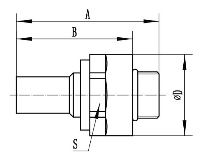
Section drawing. The face marked S is the one the seal is compressed against.
