EMS-Trade
Cooling
Loop consumables

Document ECT-01 · REV C · ISSUED 2026-09 Six lines · 48 sheets

Plate 03 · Coolant filtration · line 03 of six

The filter becomes the contamination it was fitted to remove

Housings, elements and the one instrument that says when the element is spent.

Request the specification file One business day, with the file attached
A stainless cartridge housing bolted into the return run of a liquid cooling loop, gauge ports on both sides of the lid and a drain valve at the low point of the body
PL 01

One housing on the return run. The element inside it is the only part of the loop built to be thrown away.

01

A clean filter and a full one are different risks

Section 01 · why filter

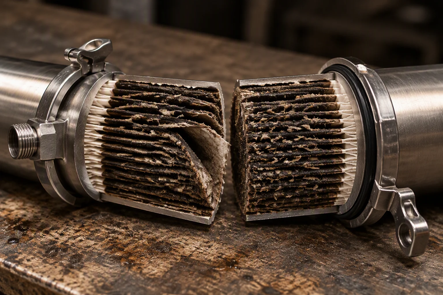
A cartridge holds what the loop shed: mill scale from a fitting, elastomer fragments from a gasket, dust that entered during fit-out. Held is the operative word. The particles sit in the pleats until the element is changed, and the change is the one moment the circuit is opened.

Past the change point the pleats load, the pressure drop climbs, and the element either bypasses at the seal or sheds what it caught toward the pump. No other component in the loop fails in that direction. The filter ends as the contaminant.

Scope of this line: the housing, the element and the instrument that reads the water. We do not supply the CDU, and we do not supply the cold plate.
1 µm Working grade The figure this line is indexed on
0.05–100 µm Absolute grades Eight steps across the range
0.5–0.7 bar Element change Pressure drop at which the element is spent
ISO 4406 17/15/12 Cleanliness target Before first power-up
A spent pleated cartridge cut open on a bench, the pleats packed with dark scale and fibre, the clean media visible only at the outer edge
FIG 01

Cut open after a season: what the loop shed is all still in there.
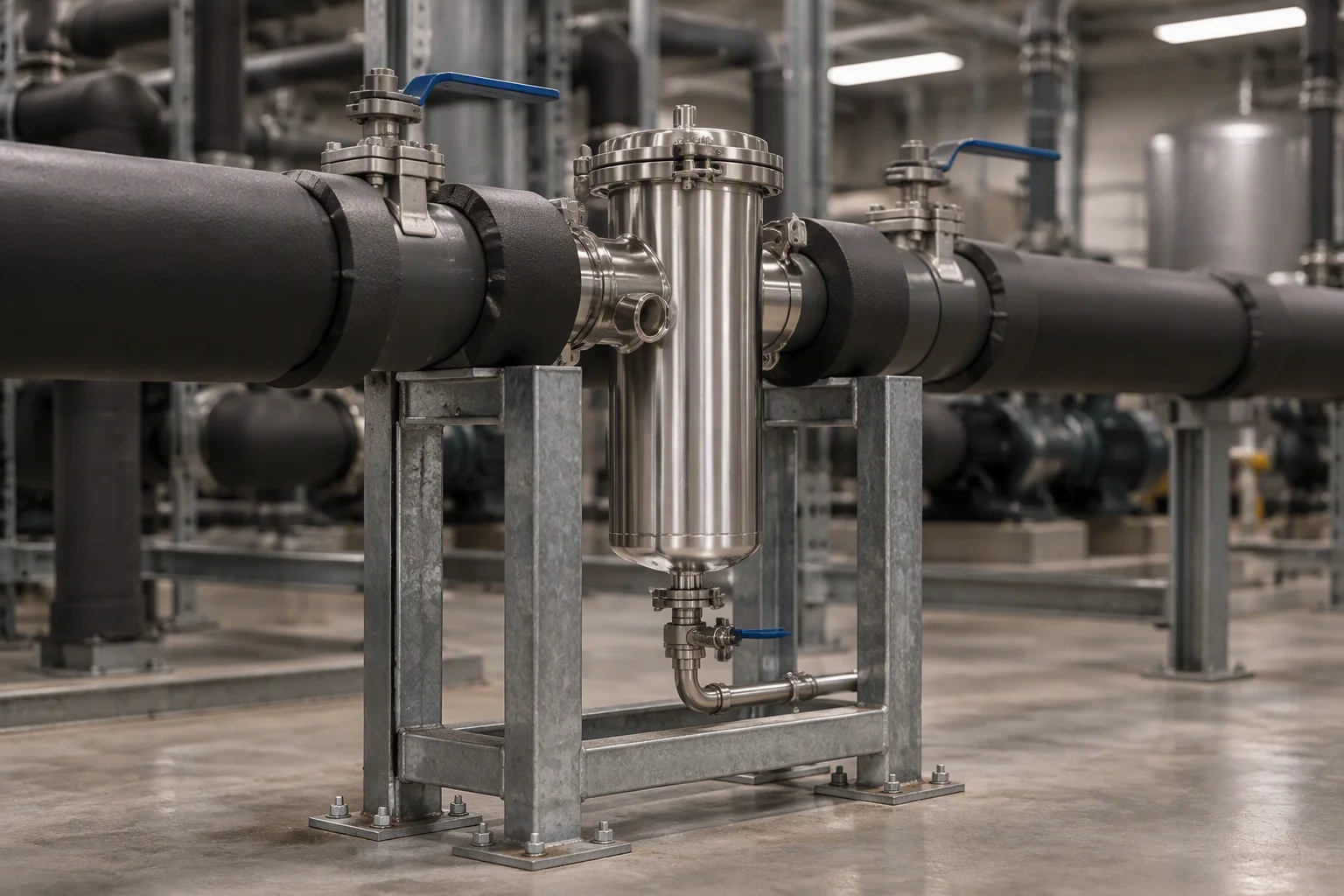
A plant room loop run with an in-line filter housing carried in a bolted frame, insulated pipe either side and a differential pressure gauge pair on the bypass
FIG 02

Every litre of the circuit passes the element. The housing sits where the whole flow reaches it.
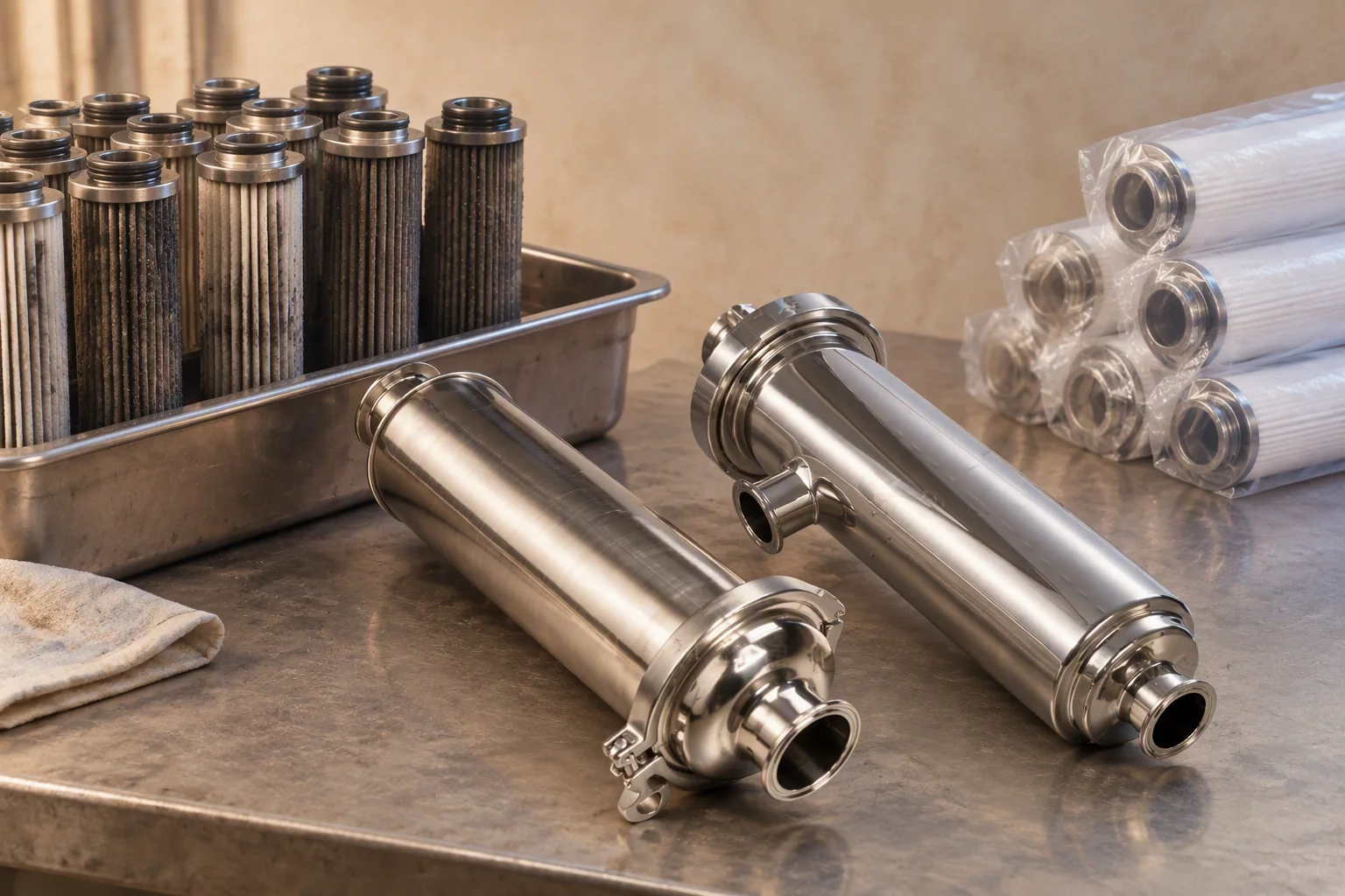
A steel tray of spent filter cartridges off one hall, each drained and stood on end, the pleat seams dark with captured debris
FIG 03

One hall's change-out. The debris in those pleats is loop material, not packing material.

02

The housing is the pressure boundary. The element is the consumable

Section 02 · housings

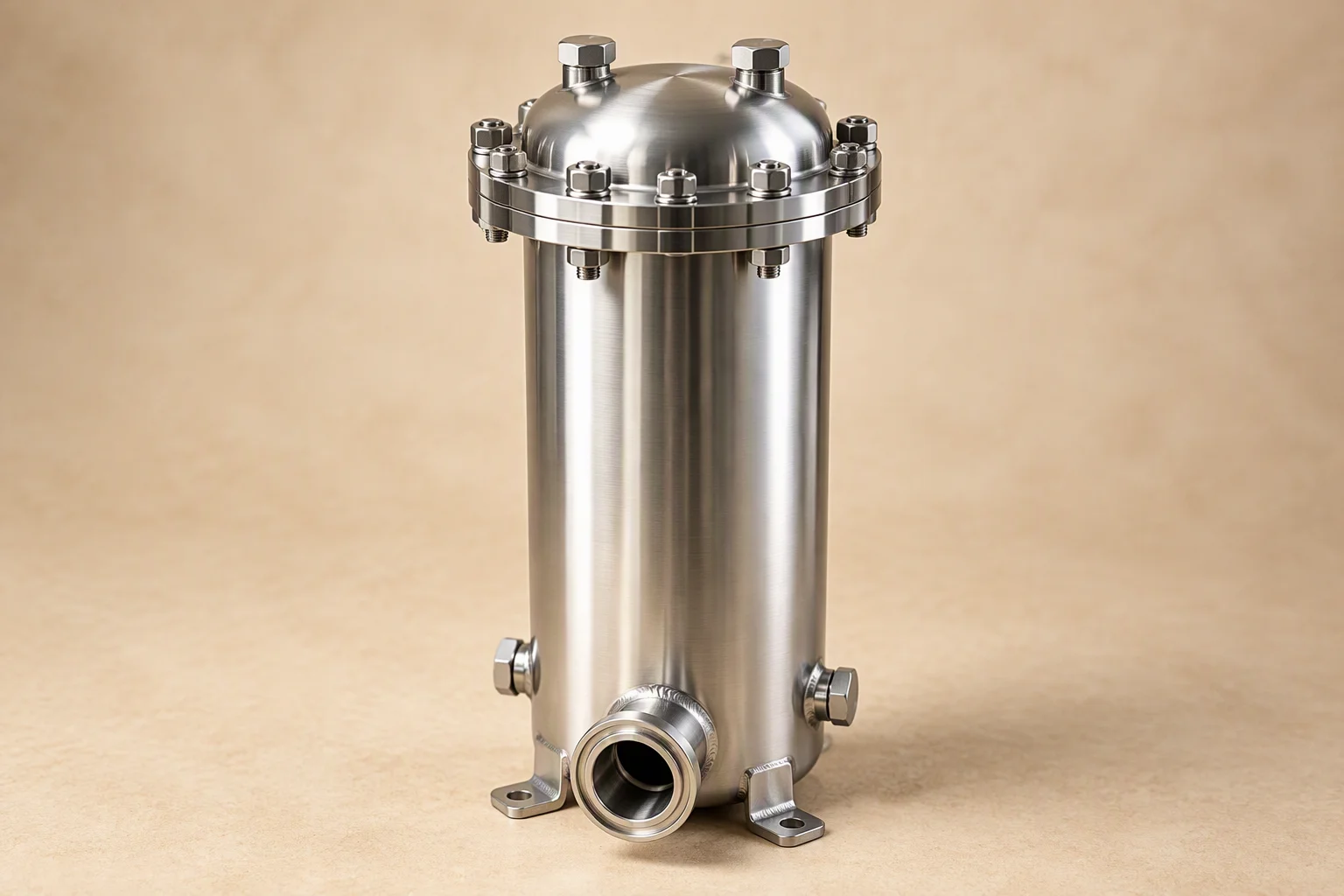
The body is welded stainless with a bolted lid, sized so the element drops in without tools and comes out without spillage. Everything the buyer cannot change later is fixed here: the material, the design pressure, the connection, the tapping either side of the element.

304 for closed treated water, 316L where chlorides or semiconductor duty rule it out. Both take the same element.
Body
304 or 316L stainless, welded body, bolted lid
Design pressure
1.0 MPa or above, tested per batch
Element size
20 in and 40 in on the main run, 10 in on a low flow branch
Connections
flanged or threaded to the branch, both faces machined
Tappings
a gauge port either side of the element, a drain at the low point
A single cartridge housing in stainless with a flanged bolted lid, eight lid bolts on a machined rim and two gauge ports blanked with hex plugs
FIG 04

Lid off in eight bolts. The rim and the seal groove are machined, not formed.
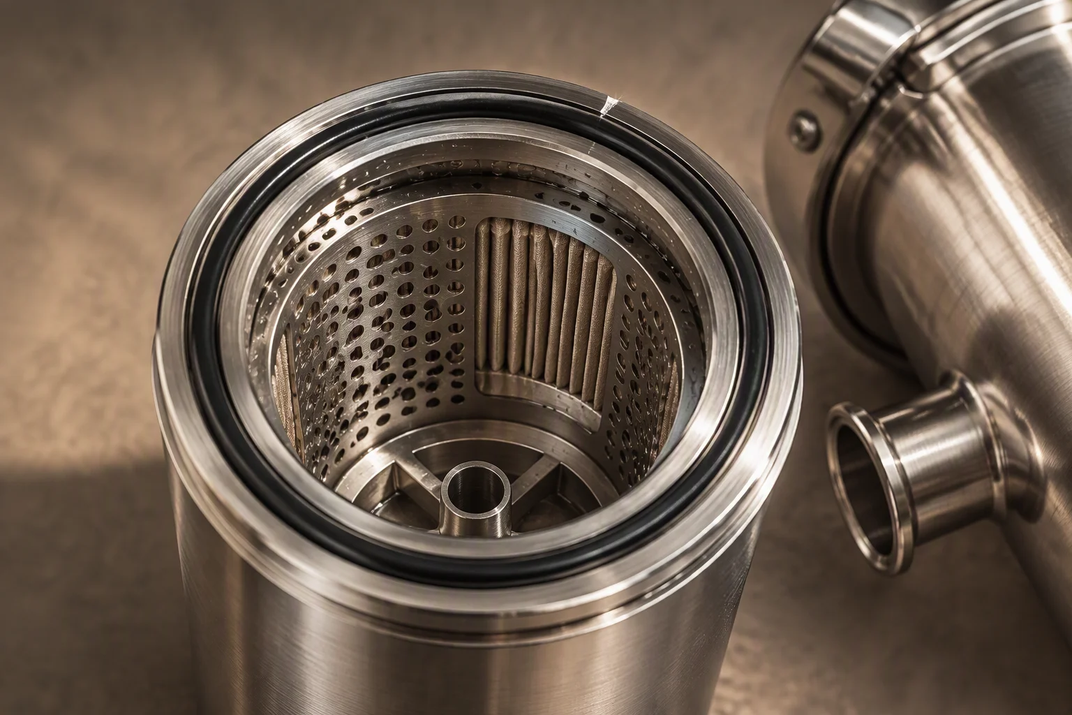
The inside of a cartridge housing: a perforated support basket, the machined seal seat at the top rim and the element guide at the bottom of the bore
FIG 05

Basket, seat, guide. The element lands on the seat and nowhere else.
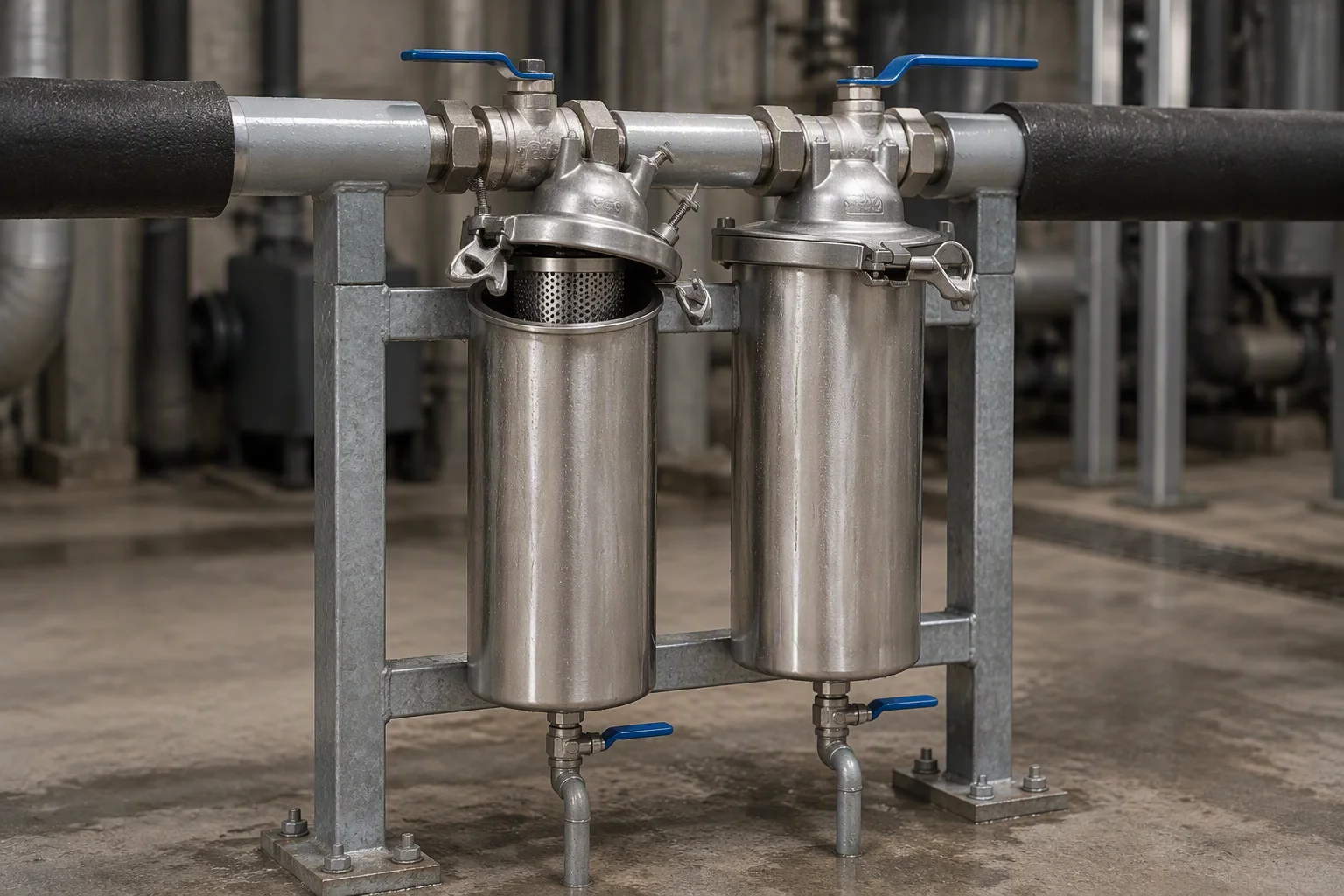
Two filter housings mounted side by side on a painted steel frame at a loop branch, isolation valves above each body and a drain line leaving the low point
FIG 06

Two bodies on one frame: one in service, one isolated. The element change happens on the dry side.
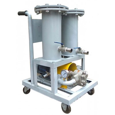
A mobile twin cartridge filter trolley on castors: two grey housings with flanged bolted lids, brass ball valves, a pressure gauge on the pump outlet and a black push handle
PL 02

The same two bodies on a trolley: the circuit is cleaned while it runs, off a bypass.

03

Absolute grades, and the one the loop is indexed on

Section 03 · element grades

The eight absolute grades on a logarithmic axis, with 1 µm marked Eight grades at 0.05, 0.1, 0.2, 0.45, 1, 5, 10 and 100 µm plotted on a logarithmic axis. The 1 µm grade carries the marker and is the grade the line is indexed on. 1 µm indexed grade 0.05 0.1 0.2 0.45 1 5 10 100 logarithmic axis · one cell per grade · all sizes in µm
0.05µm
0.1µm
0.2µm
0.45µm
1µm
5µm
10µm
100µm

The steps are not evenly spaced because the sizes are not: 0.05, 0.1, 0.2, 0.45, 1, 5, 10 and 100 µm climb a logarithmic axis. Each step is an absolute rating on the element, not a nominal one, and it is a rejection size rather than an average.

1 µm is the grade the loop is indexed on. Finer grades cost pressure drop; coarser grades leave the wear particles circulating.

Below 1 µm the element surface is the limiting factor, not the media. Above 10 µm the loop's own wear particles pass it.

Read next · Filter cartridges · Filter housings
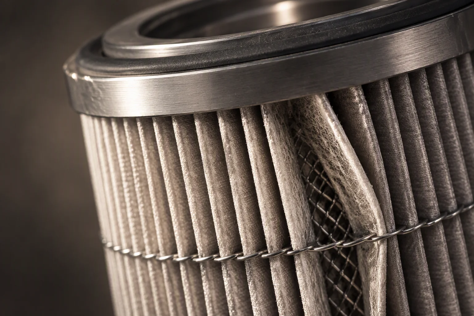
Macro of a pleated filter pack: even pleat spacing held by a spiral seam, one pleat parted to show the depth of the media behind the surface layer
FIG 07

Pleat spacing is the surface area. The grade is set behind it, in the media.
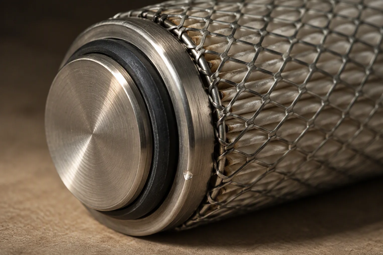
The end of a cartridge in close view: a bonded end cap, the outer support mesh and the elastomer seal ring seated in its groove
FIG 08

End cap, mesh, seal. If the seal ring is wrong, the grade on the label is a claim.

04

The instrument says what the element cannot

Section 04 · water quality

A pressure drop says the element is loaded. It does not say whether the coolant is still the coolant. An in-line channel reads conductivity in µS/cm, pH and temperature on the same return run, so a change is caught while it is still a trend.

Reading against a baseline taken at fill, not against a range printed on a box.
Conductivity
read in µS/cm, against the baseline the loop was filled to
pH
the reading that moves first when the coolant degrades
Temperature
compensates the other two, so a warm afternoon is not read as a chemistry event
Sampling
a sample valve upstream of the element, on the same run as the instrument
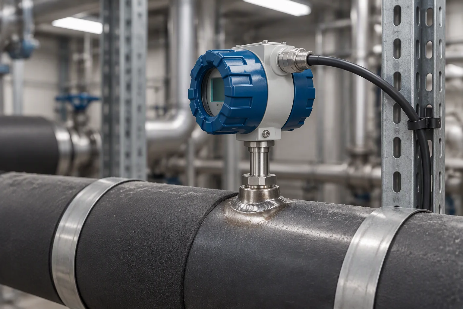
An in-line water quality transmitter on a loop return run, its head carrying a display, the sensor body screwed into a welded boss on the pipe
FIG 09

Head on the pipe, on the return run, where the whole flow has already passed the element.
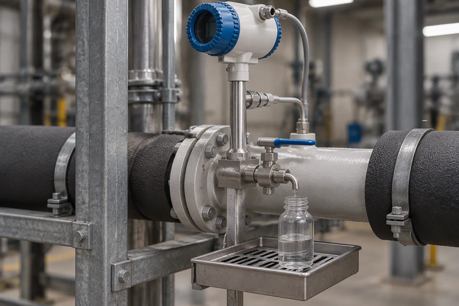
A sample valve on a loop branch with a clear sample bottle under the spout, a wet label and a marker pen on the bench beside it
FIG 10

A drawn sample beside the in-line reading: the two numbers have to agree.
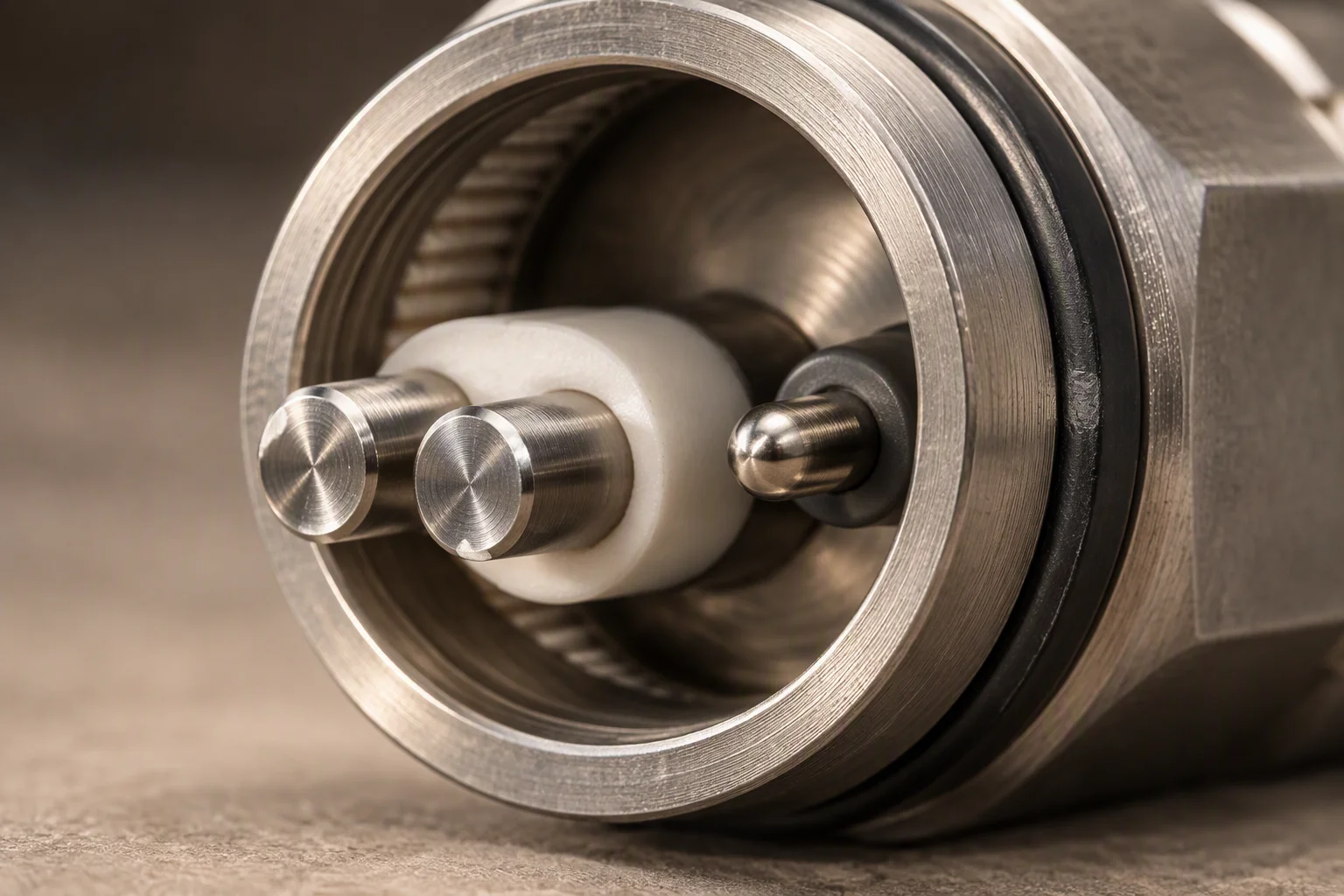
The wetted end of a water quality probe in close view: a pair of electrodes in a machined body with an insulator between them and a temperature element beside them
FIG 11

Two electrodes and a temperature element. Everything the channel reads is decided here.

Read next · Water quality · Telemetry instruments

05

Change on pressure drop, not on a calendar

Section 05 · differential pressure

Two tappings, one either side of the element, give the number the change is made on. A calendar interval cannot see a fit-out that left the loop dirty, and it cannot see a clean loop either: it replaces elements that were still working.
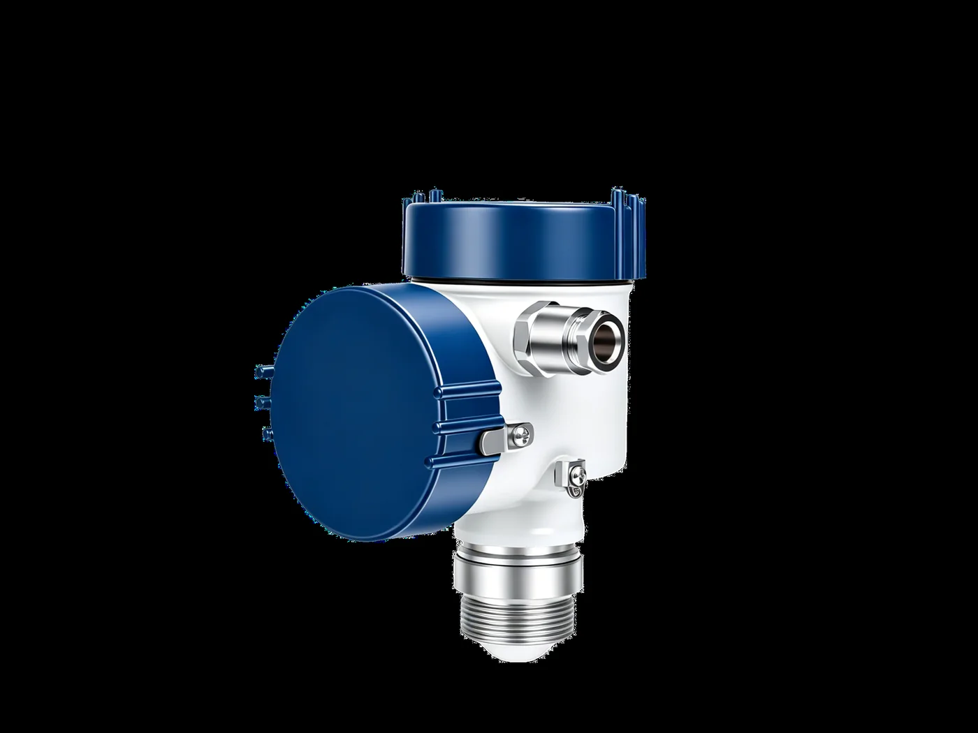
A pressure transmitter with a blue cap and a white body, a stainless process connection below it and a cable gland on the side, photographed on a plain ground
PL 03

A transmitter on the high side and one on the low side: the difference is the load.
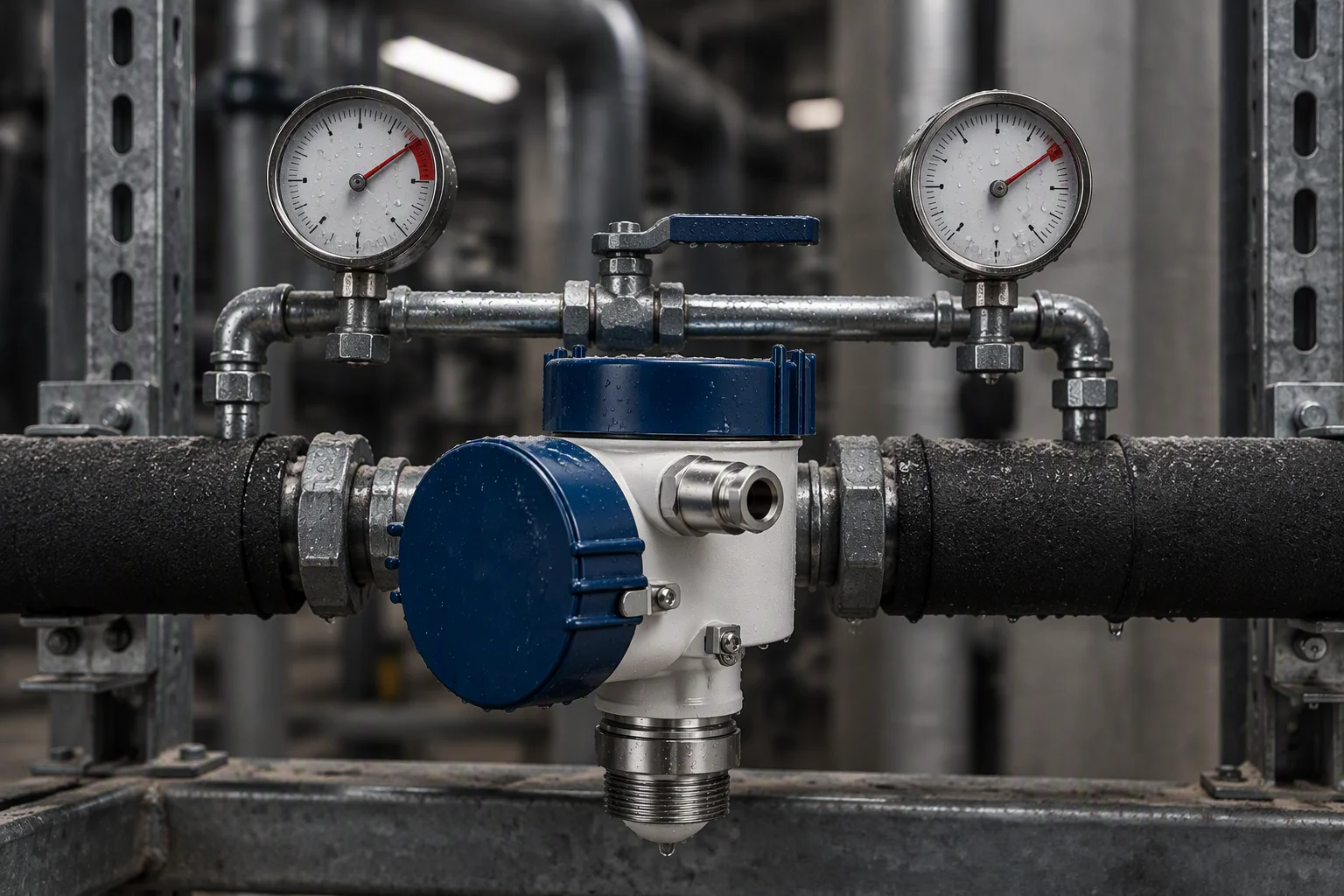
Two pressure gauges mounted on a bypass across a filter housing, one upstream and one downstream of the element, both reading on a wet needle
FIG 12

A gauge pair when there is no transmitter on site: read both, subtract, change at the number.

Change point
0.5–0.7 bar across the element
Tappings
either side of the element, on the housing, upstream and downstream
What it replaces
a change interval that was decided before the loop was filled

Read next · Filter cartridges · Filter housings

Document request

Four documents are held for this sheet. Tick the ones you need.

Tick a document, name the line and the quantity, and the file comes back attached.

The only promise on this page

One business day, with the file attached.

No other commitment is made on this sheet. Price, stock and lead time are not promised here.
If the form cannot send, the address below takes it instead: sales@ems-cool.com. A request is never accepted and then dropped.
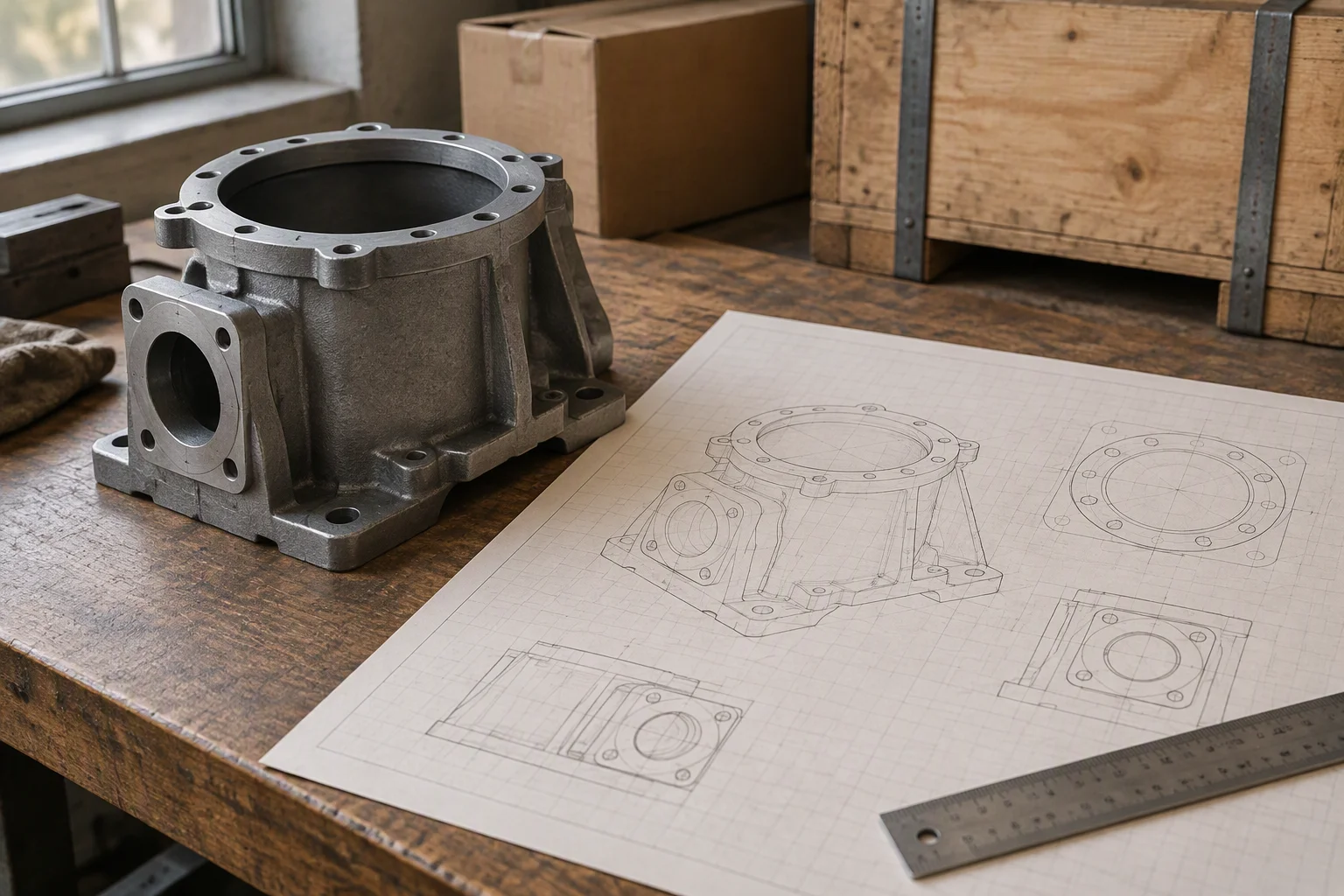
An outline drawing of a cartridge housing on a bench beside the housing itself, the lid bolt pattern and the connection faces drawn out in pencil lines
FIG 13

The drawing and the part it describes, on the same bench, before packing.
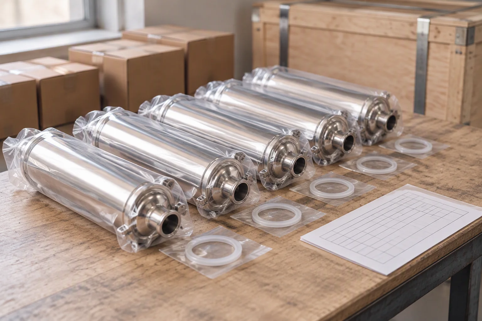
A set of sealed cartridges laid out in a row on a bench with their labels face down, the seal rings stood beside them and a batch ticket at the end
FIG 14

Sealed and ticketed per batch: the certificates follow the box, not the order.