Production residue in pipework
Scale and swarf left in pipework and heat exchangers from the build.
The interval is not a date.
Change-out at terminal differential pressure, 35 psid against a 60 psid element maximum · coolant sample every 50 to 100 days · side-stream at 5–15 % of circulating volume
Two questions get confused here. One is whether the element is loaded, and the other is whether the fluid is still in specification. Different answers, different instruments.
We supply the loop between the coolant distribution unit and the cold plate. Neither of those two parts is in the catalogue.
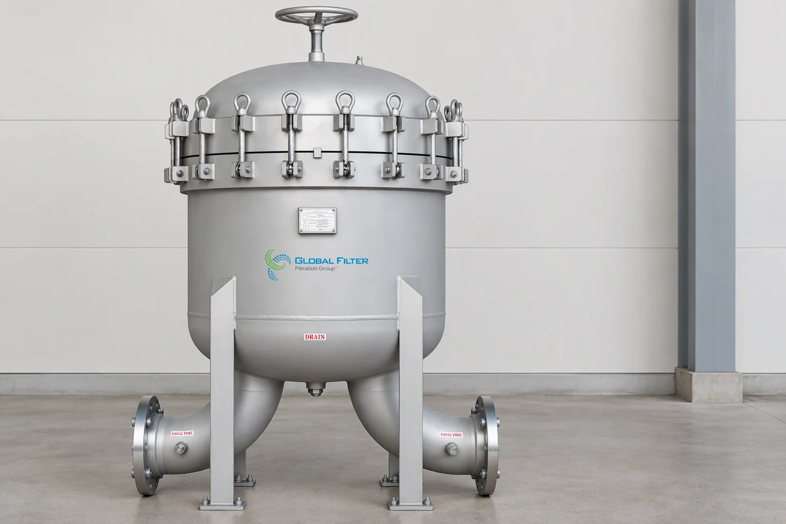
Side-stream filtration cart · the gauge leg is the instrument the interval comes from
A side-stream loop diverts 5 % to 15 % of circulating volume from the main header, filters it and returns it downstream of the take-off. Full-flow inline filtration of the whole volume costs more energy and a larger footprint, which is why the split exists. The split is a design decision, and it sets the turnover time.
At 10 % of volume per hour that is 480 L/h, a full turnover every 10 hours. Published guidance puts the practical band at a full turnover every 6 to 12 hours. At 10 % per hour a contaminant slug takes hours to reach the element, which is why filtration problems arrive slowly.
Loop 4,800 L · 10 %/h = 480 L/h · turnover 10 h · published band 6–12 h
Scale and swarf left in pipework and heat exchangers from the build.
Particles shed by pumps and mechanical components under continuous running.
Material left by the assembly and sealing steps, carried into the fluid.
Inhibitor depletion and glycol breakdown raise conductivity and organic load.
Element rating moves the rate too. Bag filtration at 1–10 µm takes the bulk load, cartridges at 0.5–5 µm do the fine polishing, and a 5 µm element blinds quickly unless it sits downstream of a bulk stage.
That is why the change-out number is a differential pressure and not a date.
| Condition | Value |
|---|---|
| Clean 2 µm element | 0.17 bar (2 psid) |
| Recommended change-out | 35 psid (2.4 bar) |
| Maximum differential | 60 psid (4.1 bar) at 20 °C |
| Cartridge temperature rating | 80 °C (176 °F) |
| Transmitter ranges | ±125 Pa · ±500 Pa |
| Transmitter accuracy | ±0.2 % of span |
| Transmitter resolution | ±0.02 % of span |
Differential pressure is read at operating temperature, not at fill temperature.
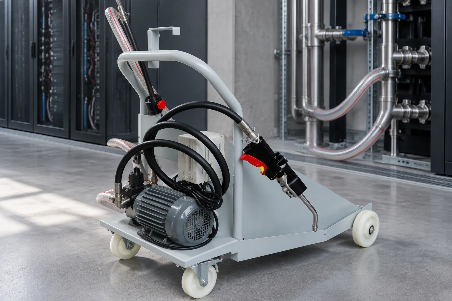
Commissioning · the day the loop is dirtiest
Stainless steel welded, ground or fabricated on site without cleaning and re-passivation to ASTM A380 / A967 practice leaves free iron in the coolant, and free iron fouls microchannel surfaces.
A glycol blend can partially separate under vacuum, so a sample after a vacuum fill is the only way to know the blend is uniform. Entrained air compounds it: degassing works best at temperatures a loop only reaches under load, so air problems surface weeks after handover.
| Parameter | Target | Guards against |
|---|---|---|
| Suspended solids, cold plate | < 5 µm | Microchannel blockage |
| Suspended solids, rear-door HX | < 10 µm | Microchannel blockage |
| Turbidity | < 1 NTU | Particulate load, optical proxy |
| pH, glycol or facility water | 7.0–9.0 | Corrosion and inhibitor effectiveness |
| Conductivity, glycol or facility water | 50–300 µS/cm | Dissolved ionic contamination |
| Hardness | < 50 ppm | Scaling |
| Chloride | < 50 ppm | Pitting in stainless steel |
| Dissolved oxygen | < 2–4 mg/L | Corrosion rate |
| Microbial | Zero active growth | Biofilm, with biocide residual held |
PG25 design basis · 25 % propylene glycol by volume · pH 8.8 · freeze −11 °C · boil 103 °C
Quarterly fits the same band. The sample is drawn from a hot closed loop, not from a drain point.
Appearance, glycol concentration, freeze point, pH, reserve alkalinity, OAT inhibitor level, electrical conductivity, ICP metals analysis, anions.
It is the buffering capacity that says how much corrosion protection is left. A published PG25 fluid carries 1.4 mL 0.1 M HCl.
ICP metals analysis detects trace metals, which is how active corrosion announces itself before a pH reading moves.
Change-out · terminal differential pressure for the element in service, not a date · Sampling · every 50 to 100 days from a hot closed loop · Instrument check · differential pressure against a known clean baseline after every element change
Particulate abrasion of a seal face is measured in weeks, and compression set in a seal in months to years. Filtration state is the one input on that list a maintenance team controls week to week.
Send the loop volume, the current element rating, the differential pressure and the last sample result, and the reply sizes the element from those four figures.
The reply returns the specification sheet, the dimensional drawing and the datasheet for the code, inside one working day.
Leave your work email and the model code. One datasheet per model, with position resolution and locating repeatability stated as separate rows.