Leader cable and terminator
A 15 ft (4.57 m) leader cable and an end-of-line terminator, both required for a supervised loop.
A conductive sensing rope reports distance by measuring resistance between two wires, and that sentence decides what it can detect.
3 decisions, in order · position resolution 0.1 m · locating repeatability ±0.6 m plus 0.25 % of channel
Buyers usually start with the third one. Getting the sensing principle wrong makes the siting irrelevant; getting the siting wrong makes a correct principle alarm twice a day.
We supply the loop between the coolant distribution unit and the cold plate; neither part is in the catalogue.
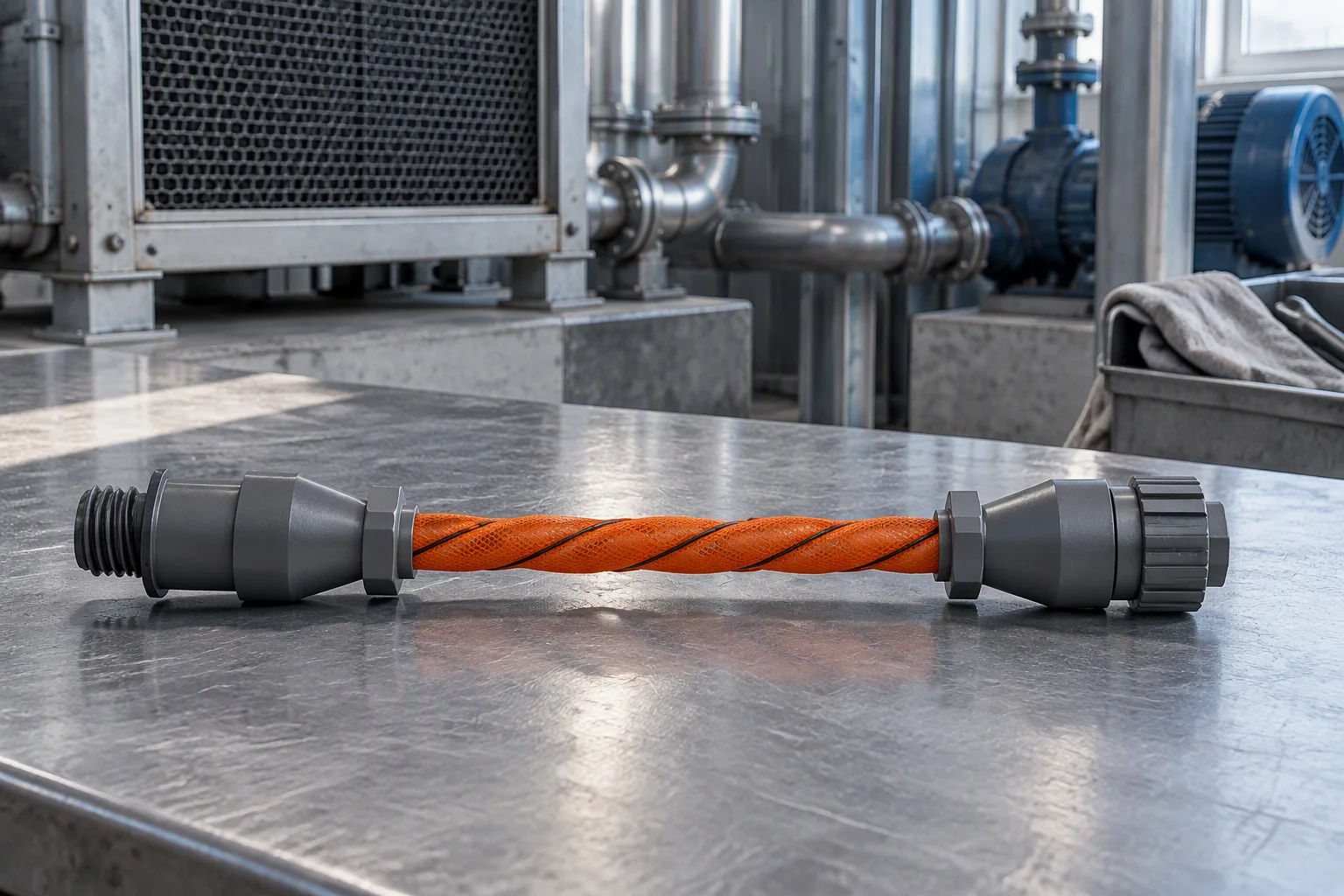
Conductive sensing rope · the two wires the distance is read between
| Principle | Detects | Locating |
|---|---|---|
| Conductive, distributed | Any conductive fluid: water, glycol blends, acids and bases | Distance-read |
| Capacitive | Water and non-conductive liquids | Zone or point |
| Fibre-optic, distributed | Water and hydrocarbons; some variants intrinsically safe | Metre scale |
| Pressure or mass balance | A loss of fluid anywhere in the loop | Loop level only |
| Acoustic or ultrasonic | Pressurised spray and jet leaks | Approximate |
Conductive rope dominates data-centre white space because it is the cheapest way to get a distance reading. Pressure and mass balance catch a micro-leak that never reaches a floor, and they cannot say which rack.
A nominal 25 % propylene glycol mix is the design basis for most single-phase direct-to-chip deployments. Sensing cable in this class detects blends at 15 % propylene glycol by weight or higher, covering PG15, PG25 and PG35.
One family is tested across 10 % to 55 % propylene glycol mixtures: the loop's concentration decides the envelope. Near-deionised water and dielectric fluids give weak or no signal. A DI loop needs the principle chosen for that fluid, and no accessory fixes it.
Design basis PG25 · floor PG15 · tested envelope 10–55 %
Keep sensing cable 6 ft, about 1.8 m, clear of the front of a downflow air unit's discharge. Cable inside that plume alarms on contamination and cannot be located: the published complaint is an alarm twice a day, with no water.
Clearance 1.8 m (6 ft) · clips 0.9–1.2 m · tags 3 m · 500 m channel: 417–556 clips, 167 tags
A leak setpoint of 150 µA for 20 seconds, and a contamination setpoint of 50 µA for 120 seconds. Water bridging the wires drives 300 µA.
Material that conducts poorly, solder flux being the classic, attracts moisture and produces 1 to 300 µA. That band crosses the leak setpoint with no water present. The contamination setpoint is adjustable, typically 25 to 300 µA.
Remedy: isopropyl wipe, or a warm soapy wash and 6–48 h drying
Contamination setpoint adjustable 25–300 µA · drying 6–48 h
Position resolution is the granularity of the reported distance, and it stays at 0.1 m on every channel length. A 500 m channel and a 50 m one report the same resolution and different accuracy.
| Channel length | Position resolution | Locating accuracy | Locating repeatability |
|---|---|---|---|
| 50 m | 0.1 m | ±0.85 m | ±0.73 m |
| 100 m | 0.1 m | ±1.10 m | ±0.85 m |
| 250 m | 0.1 m | ±1.85 m | ±1.23 m |
| 500 m | 0.1 m | ±3.10 m | ±1.85 m |
Accuracy = ±0.6 m + 0.5 % of channel · Repeatability = ±0.6 m + 0.25 % of channel
A 15 ft (4.57 m) leader cable and an end-of-line terminator, both required for a supervised loop.
10 ft (3.05 m), wherever sensing cable crosses over itself. A distance-read channel averages two wet points on one cable: a leak touching it twice is reported once, in the wrong place.
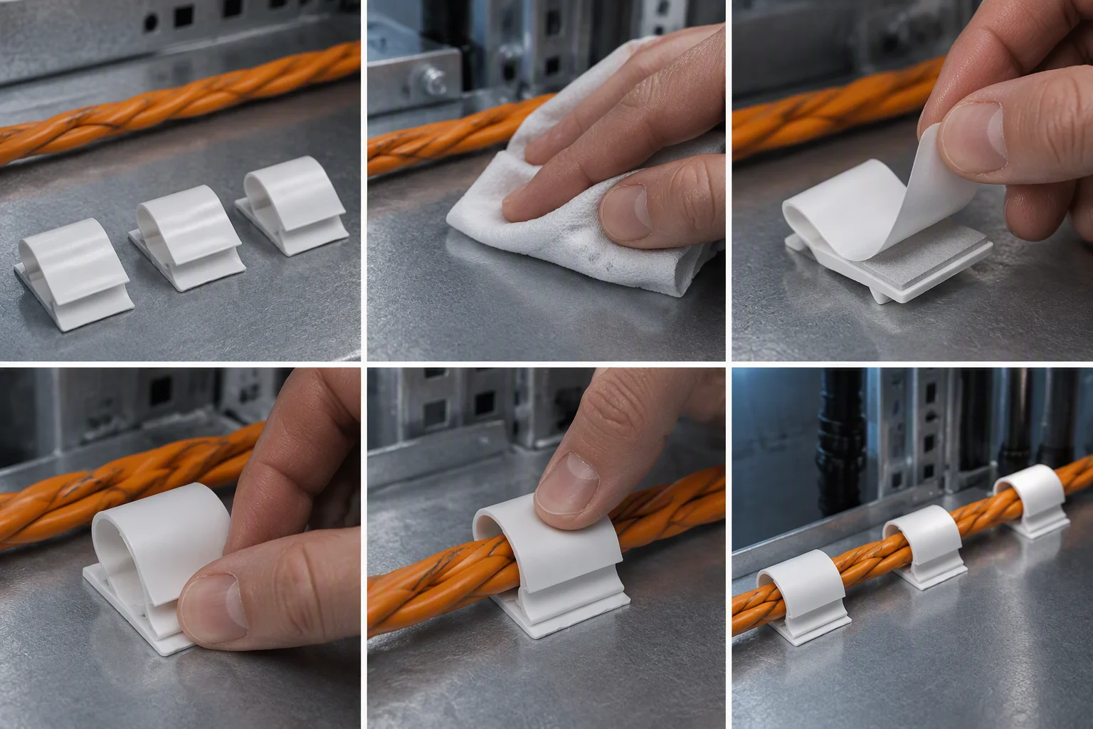
J-clips every 0.9–1.2 m, tags every 3 m.
Power supply, an enclosure or rack bracket, extension cable.
Test cable break and leak detection at least once a year, monthly preferred. Monitor cable current monthly where the panel logs it.
Controllers in this class store the last 500 to 1,024 events and trend cable current daily for 288 to 365 days.
Adjustable in 5-second steps, ±2 seconds, on distance-read controllers; fixed at 10 seconds or 2 minutes on single-zone units.
Set the response time for the space.
Scope · no coolant distribution units, no cold plates
The reply returns the specification sheet, the drawing and the datasheet for the code.
Leave your work email and the model code. One datasheet per model, with position resolution and locating repeatability stated as separate rows.