Why thermal interface materials pump out
Grease fails at the bond line, not at the die.
The paste sits where it was squeezed at assembly. Under thermal cycling it migrates outward until the interface is starved, and the joint runs hotter at the same power.
Gradual failure · found by a trend line, not by an alarm
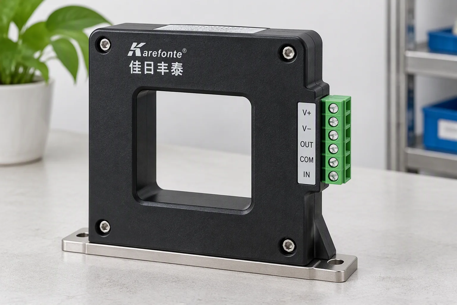
Bond line · die-cut pad on a cold plate
The same joint, drawn at one scale
Assembly on the left, after cycling on the right.
Bond line · assembly and after cycling · one scale
Two bodies, one interface, different expansion
The interface sits between a package or lid and a cold plate. Different coefficients of thermal expansion move the two bodies against each other on every power cycle. The grease absorbs that movement, and it is the layer that gets pumped.
Bond line by material class
| Interface | Figure | Set by |
|---|---|---|
| Thermal grease | 0.05 mm minimum | clamp load |
| Phase-change sheet | 0.20 to 1.0 mm | supplied thickness |
| Gap pad | 0.5 to 6 mm | supplied thickness |
| Custom pad | to 20 mm | drawing |
| Bond line | the dominant term | assembly pressure |
Assembly pressure belongs in the failure analysis, not in the installation notes.
Contact asperities · dry and filled
Dry metal touches on a fraction of its area
Two apparently flat surfaces in dry contact touch on less than 3 % of their apparent area. The interface resistance that air-filled contact creates is what a thermal material is bought to remove, and filling the interface is credited with cutting contact resistance by more than 90 %.
Interface resistance below 0.05 °C·cm²/W
Commercial phase-change sheet at ≤0.0078 °C·cm²/W over 0.20–1.0 mm, ASTM D5470
Chip reliability is estimated to fall by 5 % for every 1 °C rise in operating temperature in the 70–80 °C band. Pump-out buys that rise slowly and charges for it at the end.
Dry-out and pump-out are fixed by different things
Grease also loses carrier fluid at temperature, which hardens the paste and raises interface resistance even where the bond line survives.
The published proxy: thermal weight loss
Below 0.2 % after 48 hours at 125 °C, with dry-out resistance declared to a 150 °C ceiling.
| Class | Ceiling | Proxy |
|---|---|---|
| Thermal grease | 150 °C | thermal weight loss |
| Phase-change sheet | 125 °C | thermal weight loss |
| Silicone pad | 125 °C | thermal weight loss |
Weight loss against soak temperature
The compliance question behind a materials detail
Free silicone oil migrates out of a pad or a grease, coats contact surfaces and can reach the coolant loop. A European buyer asking for a low-siloxane or silicone-free thermal material is answering a compliance question rather than expressing a preference.
1 % or less, on a 30 mm filter paper disc at 25 % compression, 125 °C, for 48 hours.
Past 240 substances, and it includes the silicones D4, D5 and D6.
Published as a D3–D20 figure. One pad is below 20 ppm, with outgassing at TML 0.170 % and CVCM 0.010 % by ASTM E595.
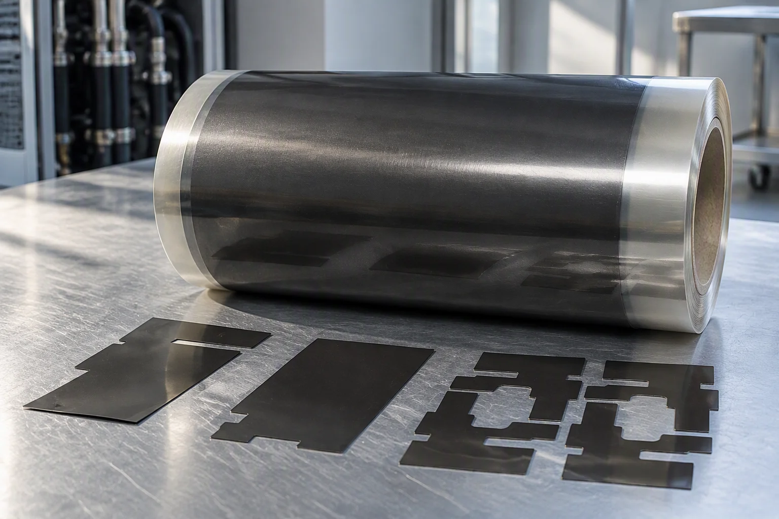
A sheet that softens in place
A phase-change sheet is solid at room temperature and softens in service, wetting the surfaces at a transition a running loop reaches anyway: 45 to 55 °C by ASTM D3418. It stays in the gap, closing the pump-out path.
8.5 W/m·K through-plane · 0.20–1.0 mm · ≤0.0078 °C·cm²/W by ASTM D5470, test pressure not published · ≥3.0 kV/mm · −40 to +125 °C · UL 94 V-0
The cost is assembly discipline: the pad stays below its transition until the joint is closed.
The codes behind this post
Ask for another codeThe second countermeasure
The pad trades a little thermal performance for a bond line that cannot migrate.
| Property | Grease | Phase change | Cured pad |
|---|---|---|---|
| Bond line under cycling | pumped outward | held in the gap | cannot migrate |
| Impedance, with its condition | 0.020 °C·in²/W at 30 psi | 0.0078 °C·cm²/W | 0.154–0.539 at 10 psi; 0.061–0.129 at 50 psi |
| Thickness | 0.05 mm minimum | 0.20–1.0 mm | 0.5–5 mm · 32 Shore 00 |
| Its failure mode | starved centre | dry-out | delamination |
Impedance against pressure
Two variants matter at a warped plate: an ultra-soft pad at 1.2 W/m·K over 1.0 mm and 10 Shore 00, at 10, 30 and 50 psi, and a high-rebound oriented pad at 70 % rebound.
Adhesive area trades assembly convenience against interface resistance: more glue points hold the pad better and conduct worse.
A conductivity figure with no pressure and no thickness is not a specification
ASTM D5470 returns apparent thermal impedance at a controlled pressure and thickness. Conductivity is derived by measuring impedance at several thicknesses and regressing: the intercept is contact resistance and the slope gives the conductivity.
Measurement directions on one pad
A 2× difference in conductivity does not produce a 2× difference in impedance at the same bond line. Send the gap, the assembly pressure and the target impedance rather than a conductivity target.
Oriented pads also carry an in-plane figure, measured along the plane rather than across it. It is a different measurement, and it does not share a column with any through-plane figure on this page.
Through-plane · across the thickness · the figure every table here carries
Ask for the specification sheet
Leave your email and the model code. The specification sheet, the drawing and the datasheet for the code come back within one working day.