Flow shows the symptom; differential pressure shows the cause, and it moves first
Flow to plus or minus 0.75% of rate, and an element change-out trigger at 35 psid, 2.4 bar.
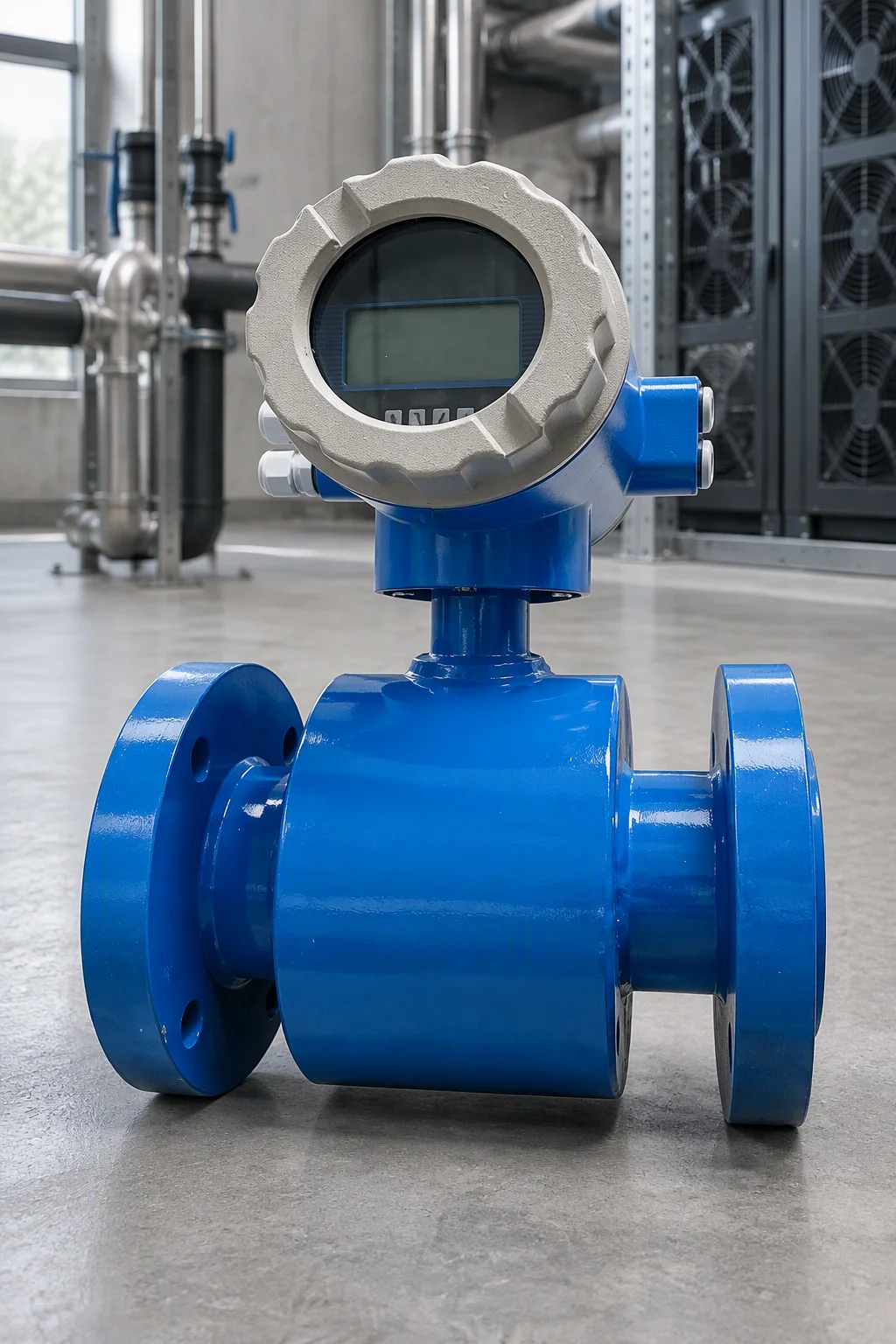
Full-bore meter on the header.
The element window, three pressures
A rising differential pressure at steady flow separates a loading element from a closed valve.
| Point | Value |
|---|---|
| Clean 2 µm | 0.17 bar · 2 psid |
| Change-out | 35 psid · 2.4 bar |
| Maximum | 60 psid · 4.1 bar at 20 °C |
| Clean to change-out | ~17× |
| Clean to maximum | ~30× |
Past change-out, flow and heat rejection fall and the server downclocks. A blocked 100–300 µm channel removes local heat rejection.
A low-range transmitter cannot display the terminal pressure
| Row | Value |
|---|---|
| Ranges | ±125 Pa and ±500 Pa |
| Accuracy | 0.2% and 0.02% of span |
| Connection | 1/8 in NPT |
| Full scale, calculated | 0.018 psi and 0.0725 psi |
| Verdict, calculated | 35 psi is ~480× the 0.0725 psi span, so neither unit displays it |
| Liquid monitor | span to 2.4 bar, line rating above 150 psi |
The low-range units suit gas-side monitoring; EMS-CF-FP-DP is catalogued on the liquid window. Full row set on the sheet.
Two meter families
| Parameter | FP-FL | FP-FC |
|---|---|---|
| Line sizes | 1–24 in, DN25–DN600 | DN 4, 8, 15, 25 |
| Accuracy, velocity | ±0.75% of rate; ~20 m/s | tiers 0.25, 0.5, 5% |
| Minimum conductivity | 5 µS/cm | — |
| Pressure rating | 290 psi; carbon steel | PN 16; PFA liner |
| Liquid temperature | −25 to 80 °C | EPDM −20 to 130; Viton 0 to 150 |
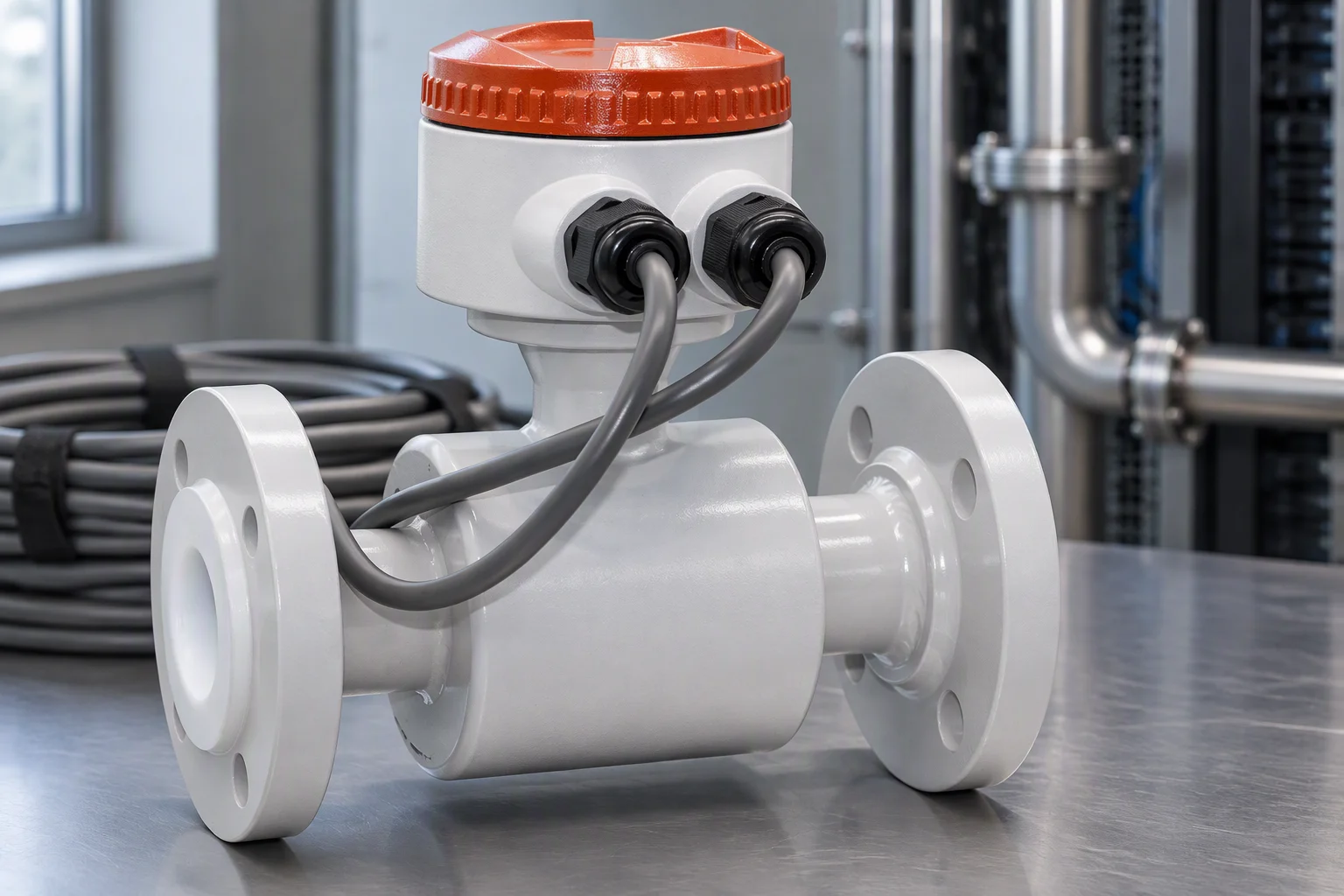
Grounding rings and liner.
The meter must match the fluid
Needs 5 µS/cm minimum: a glycol loop at 50–300 clears it, a de-ionised loop at 0.2–20 can sit below and read zero.
1.7 to 8.2 mPa·s over 15–55% glycol, so the usable low-flow end moves with turndown.
Without its specified straight runs a meter loses ~1.5% of reading.
1.66 L/s through DN25 is ~3.4 m/s, inside the 20 m/s ceiling.
Where each instrument sits
Differential-pressure figures compare only at a stated temperature: 20 °C.
| Position | Instrument | Purpose |
|---|---|---|
| pump discharge | full-bore meter | loop flow, ±0.75% of rate |
| side-stream branch | compact meter, DN4–DN25 | the 5–15% divert |
| side-stream element | ΔP transmitter | change-out at 35 psid |
| heat exchanger | ΔP transmitter | fouling trend |
| make-up water | conductivity cell | de-ionised 0.2–20; glycol 50–300 µS/cm |
Reading the two together
| Flow | ΔP | Reading |
|---|---|---|
| steady | rising | loading normally; change at 35 psid |
| falling | rising | loading fast; check prefiltration |
| falling | steady | blockage elsewhere |
| steady | steady | element clean; check the load side |
| falling | falling | pump or system |
One row is the loading signature. A blocked microchannel removes local heat rejection until the server downclocks.
How a row gets filled
An unsourced row stays open, confirmed at order. It is never filled with a plausible figure.
| Open row group | What stays open |
|---|---|
| Low-range ΔP unit | pressure limits, overload rating |
| Flow meters | turndown ratio |
| Cartridges | dirt-holding capacity; end-cap nomenclature such as DOE, SOE, 222, 226, bayonet |
| Conductivity cells | accuracy as a percentage of reading, calibration interval |
| pH sensors | accuracy, resolution, ISFET, calibration, sensor life |
| Turbidity | accuracy and resolution |
Six codes, one sheet each
Download the EMS-CF-FP-DP specification sheet PDF| Code | Instrument |
|---|---|
| EMS-CF-FP-FL | full-bore meter |
| EMS-CF-FP-FC | compact meter, 0.14–1.66 L/s |
| EMS-CF-FP-D1 | transmitter, ±125 Pa |
| EMS-CF-FP-D5 | transmitter, ±500 Pa |
| EMS-CF-FP-DP | element ΔP monitor |
| EMS-CF-FP-K | installation kit |