EMS-Trade
Cooling
Loop consumables

Document ECT-01 · REV C · ISSUED 2026-09 Six lines · 48 sheets

Line 06 · fill and flush · sheet 2 of 3

Three figures size a cart, and only one of them is ours.

Tank volume and pump flow come off the loop that is being filled. The number of filtration stages comes off us, and it is the one that decides whether the flush reaches the target or just moves the debris around.
Request the specification file Cart schedule, with the assembly drawing
Two stages 10 µm then 1 µm
1.0 MPa Housing design pressure
304 · 316L Housing material
0.5 – 0.7 bar Element change differential
20 in · 40 in Element lengths
EN 10204 3.1 Wetted metal certificate
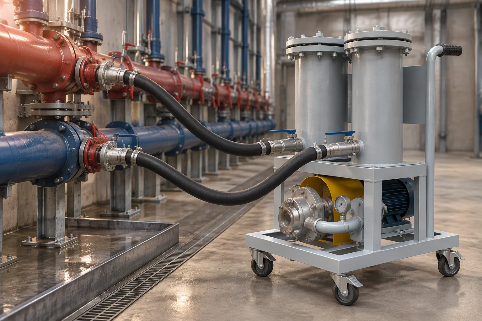
A fill and filter cart drawn up to a row manifold in a plant room, its two hoses landed on the supply and return ports with the castors braked
FIG 01 ·

A cart in position. Everything on this sheet is drawn from the twelve inches behind those two couplings.

01

The cart in section

Assembly · six callouts, one per row of Schedule A

Section through the fill and filter cart Vessel 1 Pump 2 Stage 1 3 Stage 2 4 Δp 5 Meter 6 to the loop Frame, castors, and the two couplings on the drawn face

Callouts

  1. 1Vessel. Sized on the loop volume plus the drain-down, not on a catalogue number.
  2. 2Pump. A self-priming unit matched to the loop's design flow, read on the meter at 6.
  3. 3Stage one. A 10 µm element, carrying the bulk of what the loop gives up.
  4. 4Stage two. A 1 µm element, holding the rating while stage one loads.
  5. 5Differential gauge. One gauge across the pair; 0.5 – 0.7 bar is the change point.
  6. 6Flow meter and the sampling point, upstream of the outlet coupling.
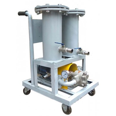
A two-housing filter cart photographed on a white ground: two stainless bowls on a painted frame, a valve on each bowl, a gauge and a self-priming pump at the base, four castors
FIG 02 ·

The assembled article. Two bowls, two valves, one gauge, one pump: the section above is what is inside that frame.
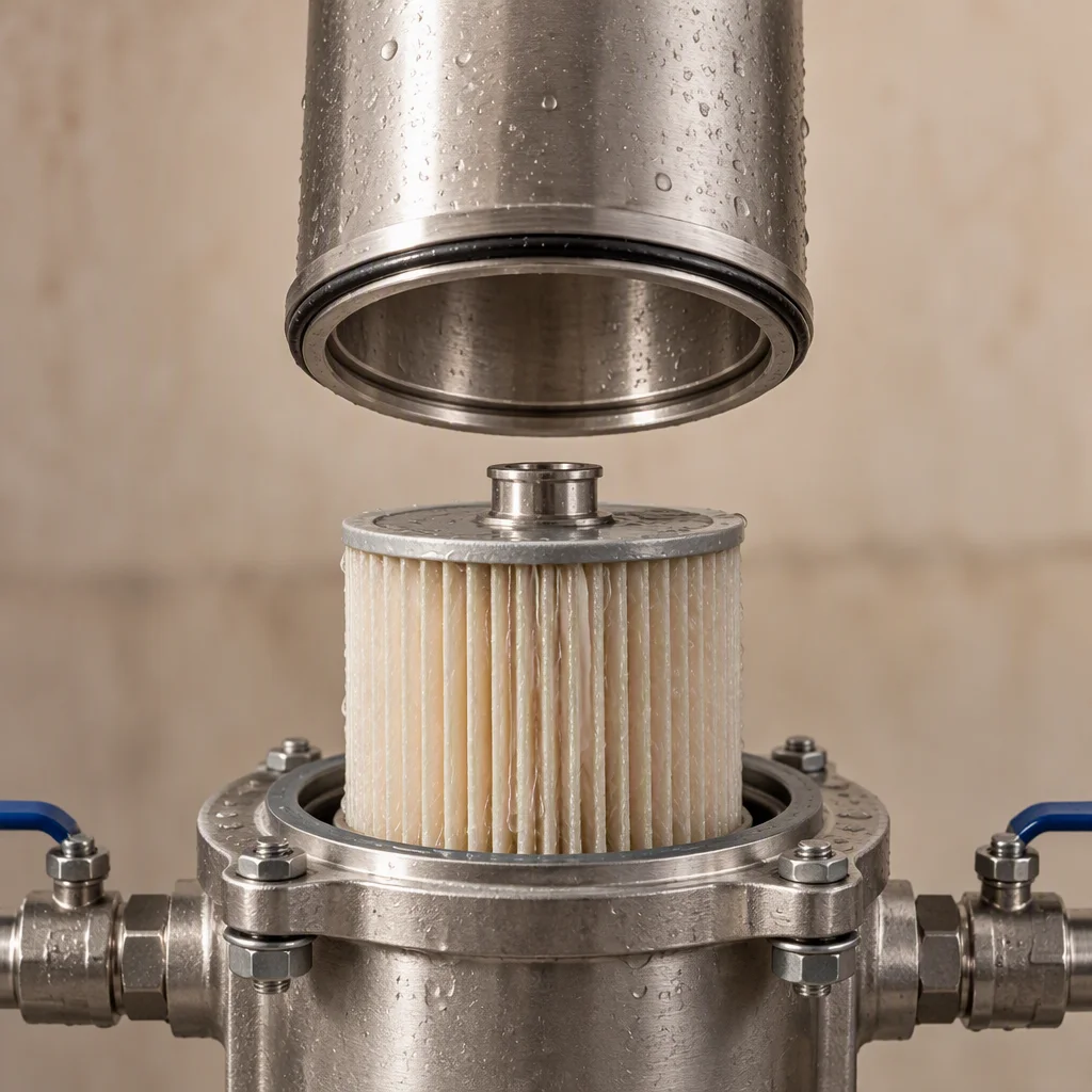
A filter housing bowl lifted off its head, the element still seated on the head spigot and the O-ring sitting in its groove at the rim
FIG 03 ·

One bowl off. The O-ring is in the head, not in the bowl, and that is the only joint the fitter touches on a change.

02

Every wetted part, layer by layer

Schedule A · in the order the fluid meets them

Wetted path · what the fluid touches, from the inlet coupling to the outlet coupling
No Part Material Figure Why it is that
01 Housing shell both stages 304 or 316L ≥ 1.0 MPa Design pressure. 316L where the flush water is aggressive or the owner writes it into the specification
02 Element, stage one absolute pleated media 10 µm Takes the load. On a new loop this element is changed more often than the second
03 Element, stage two absolute pleated media 1 µm Holds the rating. Both come off the eight-step ladder that runs 0.05 µm to 100 µm
04 Bowl and head seals the only joint EPDM −40 ~ +99 °C The quoted coolant range of the elastomer on this line
05 Hose and couplings cart to loop EPDM, stainless 1.38 MPa The same hose as the rest of the loop, with a burst figure above 5.5 MPa behind it
06 Gauge and meter bodies not wetted stainless EN 10204 3.1 Certificate on the metal parts, one sheet per batch with the order
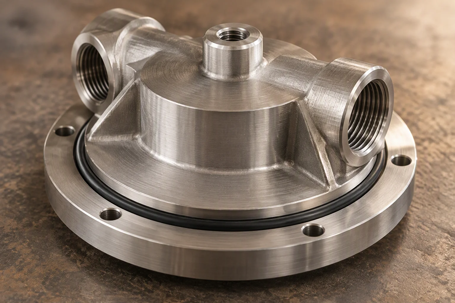
A stainless housing head on a bench with its machined rim, its O-ring groove and the threaded ports in view under a raking light
FIG 04 ·

The head. Groove, threads and seat are all cut into one piece, so there is no second joint to leak.
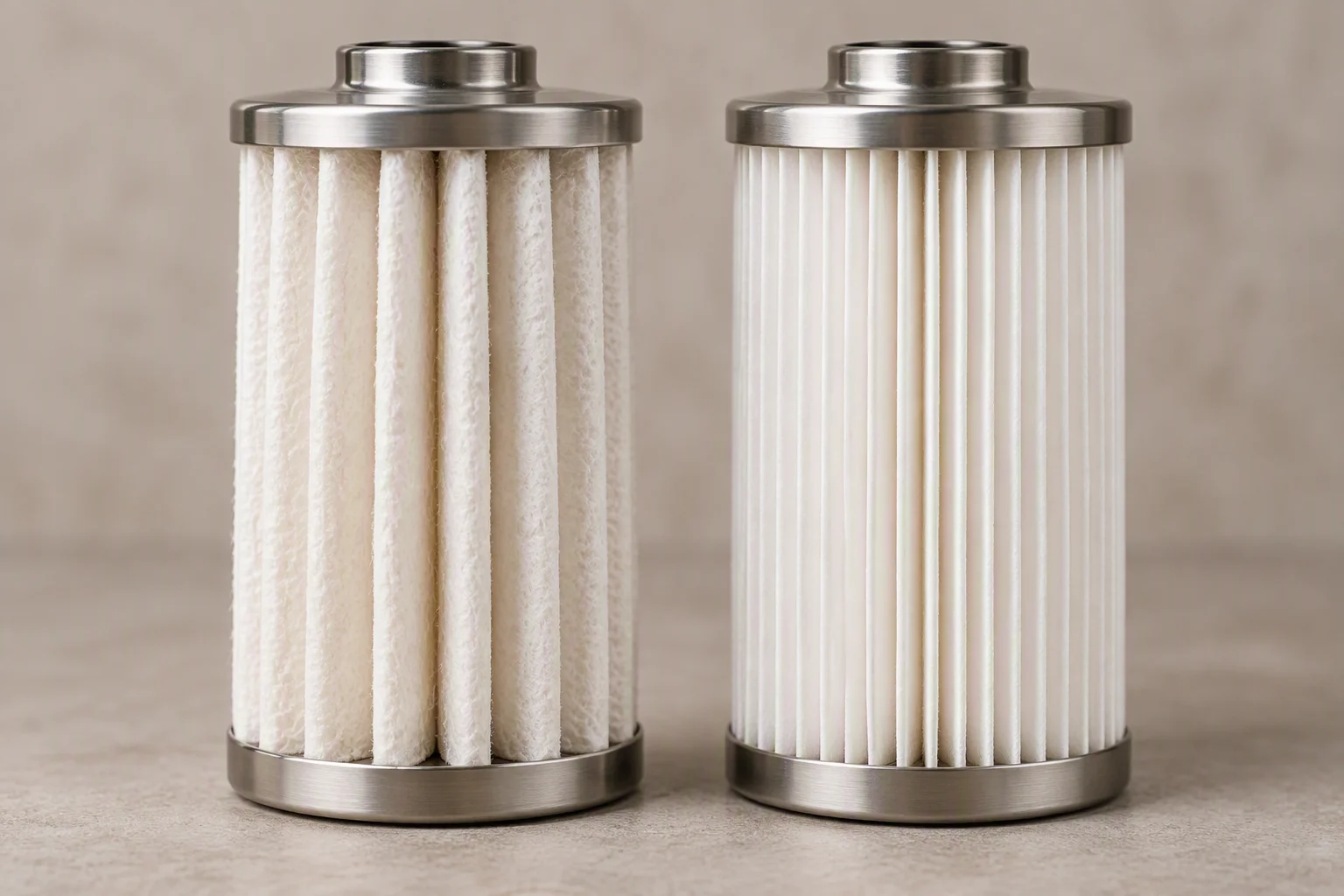
A pleated element held out of its housing with the pleats opened slightly, showing the coarse face of the first stage against the finer face of the second
FIG 05 ·

Two ratings, two faces. The difference is in the media, not in the housing that holds it.
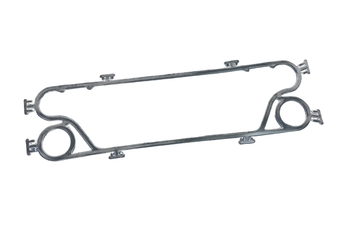
A black elastomer gasket on a dark ground, its channel profile running the full length of the part with moulded locating tabs along one side
FIG 06 ·

The seal profile itself. A moulded profile, not a cut ring: the channel is what gives it its recovery.

03

What happens to the cart before it is crated

Process · four operations, each with the check that closes it

OP 01 Shell and weld Housing shells formed and welded, then proof tested at the 1.0 MPa design pressure before anything is fitted to them.
OP 02 Assemble and leak check Bowl, head, gauge, meter and pump landed on the frame; every joint checked wet at the working figure.
OP 03 Run on water Both stages fitted and the cart run, so the differential can be read off zero and the meter checked against a measured fill.
OP 04 Dry, document, crate Drained and dried, elements boxed separately, crate marked to ISPM 15 with the certificate inside.
Each operation ends on a record, not on a signature. The four records are what the certificate and the test report are written from.

A cart is not a pressure vessel and is not treated as one. The figure that closes OP 01 is the design pressure of the housing; the figure that closes OP 03 is the differential the gauge reads on clean water, which is the zero the fitter works from in the field.

Assembly and testing happen inside the supply network, against the drawing in this sheet. We do not put the cart together ourselves, and this sheet does not claim a plant of our own.
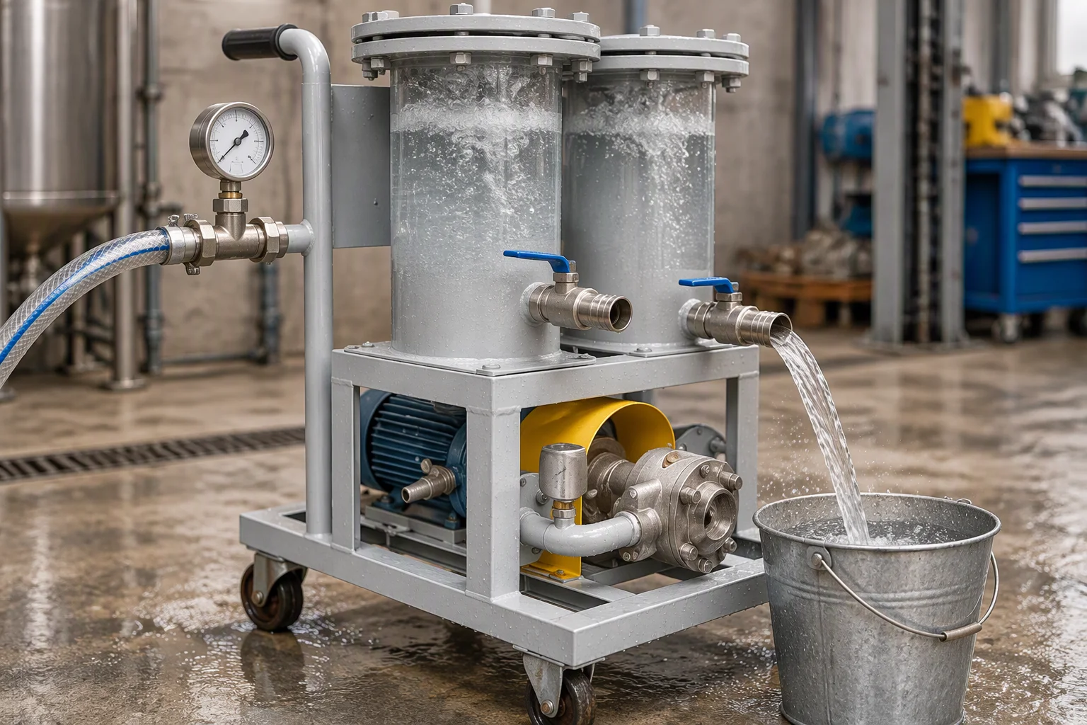
A cart on a test bench with water in both bowls, a pressure gauge connected at the inlet and a bucket under the drain valve catching the first flow
FIG 07 ·

OP 03. Run on water so the gauge has a zero and the meter has a check before it is crated.
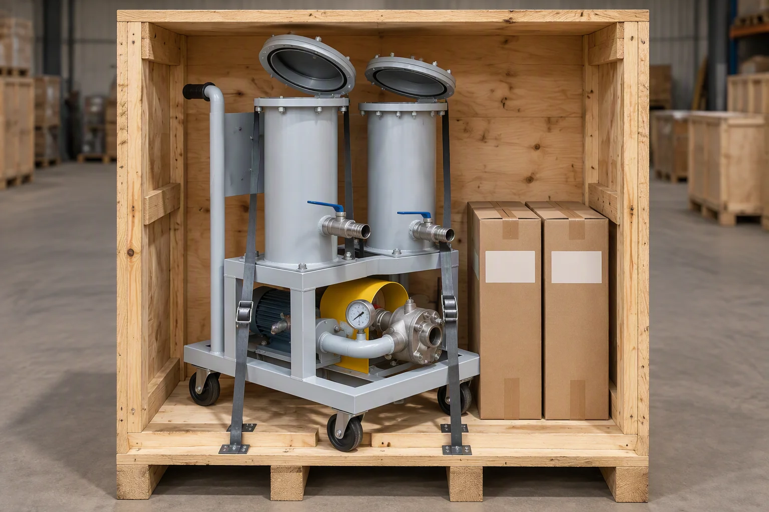
A cart strapped into an open export crate on a pallet, its bowls drained and open, with two element boxes standing beside the frame
FIG 08 ·

OP 04. Drained, strapped, crated. Elements travel beside the cart rather than fitted to it.

04

The two faces the cart is judged on

Detail · bowl joint and coupling face, photographed

Every joint on a cart is one of two kinds: something an O-ring sits in, or something two flat faces are drawn together on. The first is tolerant of a scratch, the second is not.
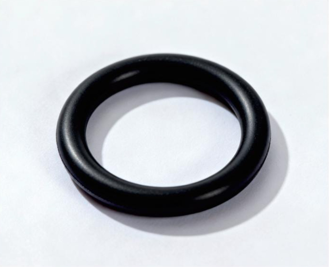
A single black elastomer O-ring on a white ground, its section even all the way round with no flat or moulding flash on the inner edge
FIG 09 ·

The bowl ring. Even section, no flash on the inner edge: a ring that has been stored flat is a ring that seals.
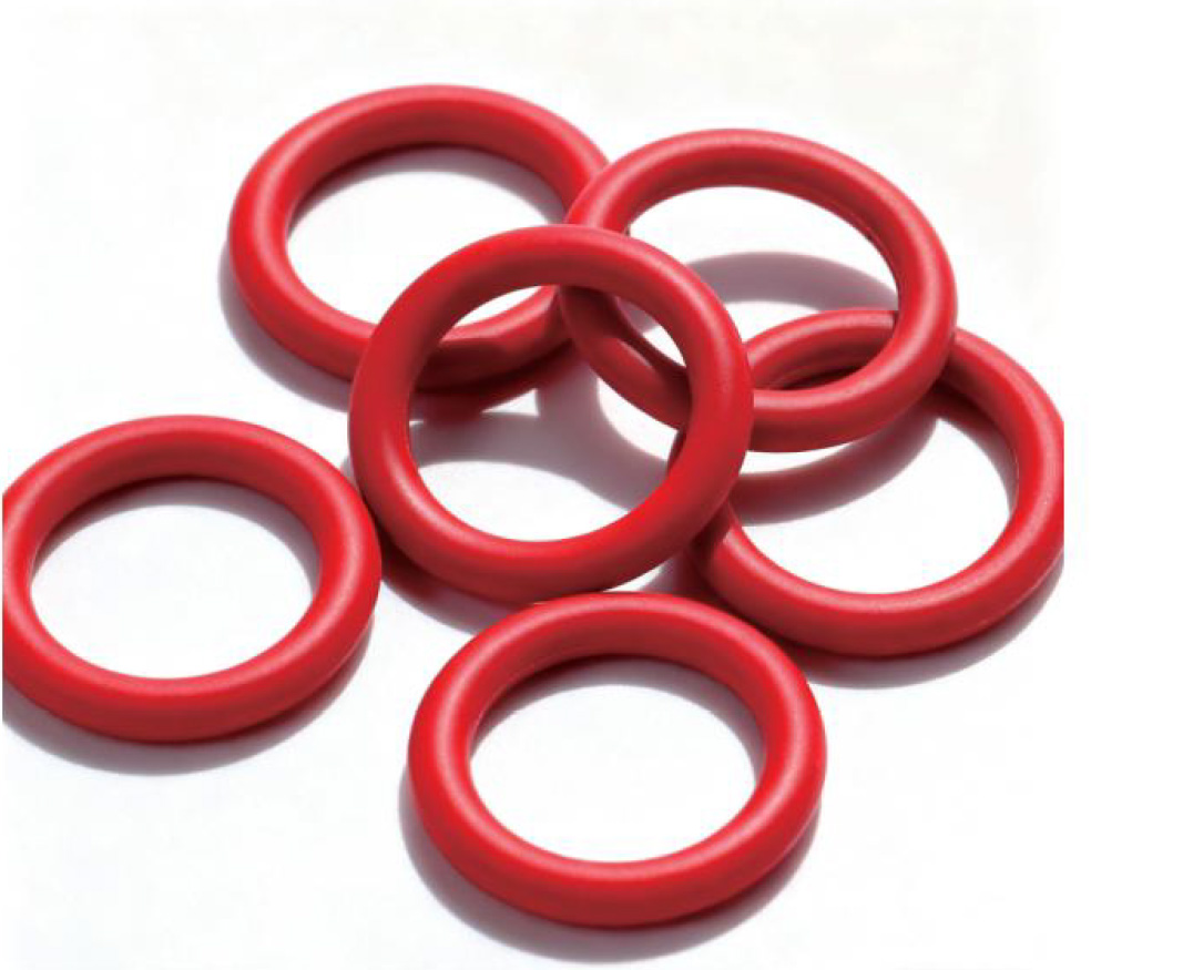
Seven black O-rings laid out on a white ground in a loose group, all of the same section and none of them flattened or kinked
FIG 10 ·

A spare set. Consumable, and the one part of a cart that is expected to be replaced before the housing is.
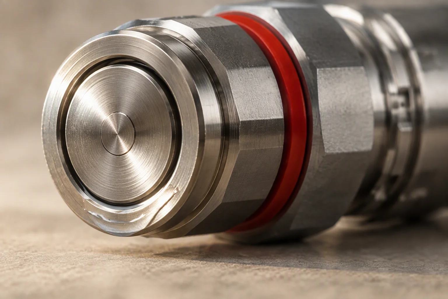
The machined sealing face of a coupling photographed close and raking, the concentric turning marks visible under the light with no scratch across them
FIG 11 ·

A good face has marks and no scratches: the marks are the finish the drawing asks for, the scratch is what a wipe with a rag leaves.
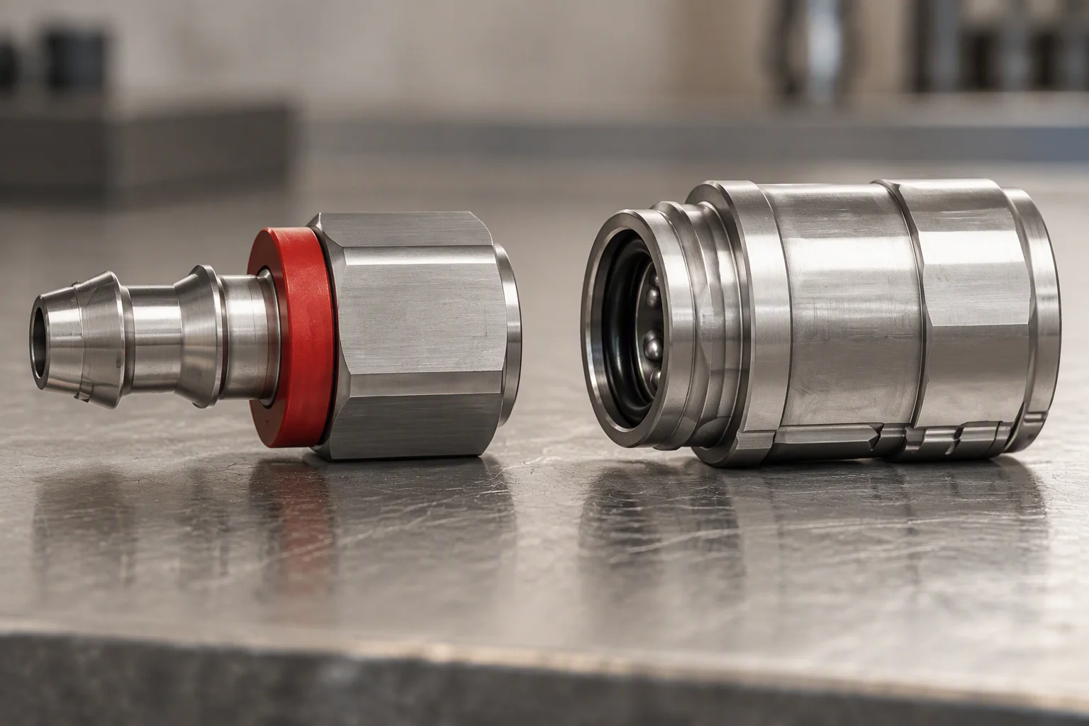
Two couplings of the cart's hose laid side by side on a bench with their dust caps off, the internal face of one caught by the light
FIG 12 ·

Caps off on the bench, not in the plant room. A face that has been open in a plant room is a face with something on it.

05

What ships with a cart

Documents · the pack is part of the order, not an extra

Assembly drawing
the section above, dimensioned: footprint, height, hose lengths and both coupling sizes
Specification sheet
vessel volume, pump curve, both stage ratings and the connection sizes as ordered
Material certificate
wetted metal to EN 10204 3.1
Test report
proof at the 1.0 MPa housing figure, and the hose assembly behind it at 5.5 MPa
Element record
rating and batch of both elements, so the next change is ordered against a number
Packing
elements boxed separately from the cart, crate to ISPM 15, sampling 7–10 days and production 25–35 days
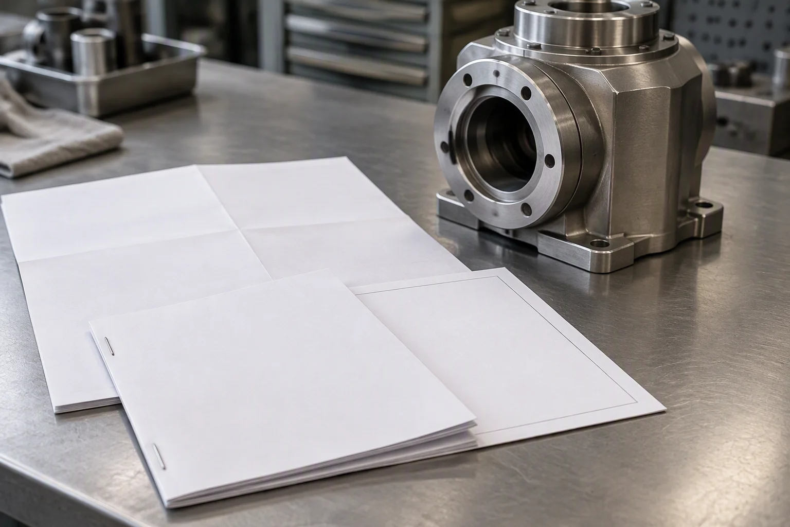
A document packet on a bench beside a housing head: a folded drawing, a stapled test report and a certificate sheet, all blank of print
FIG 13 ·

Five documents leave with every cart, and the drawing is the one that gets used first.
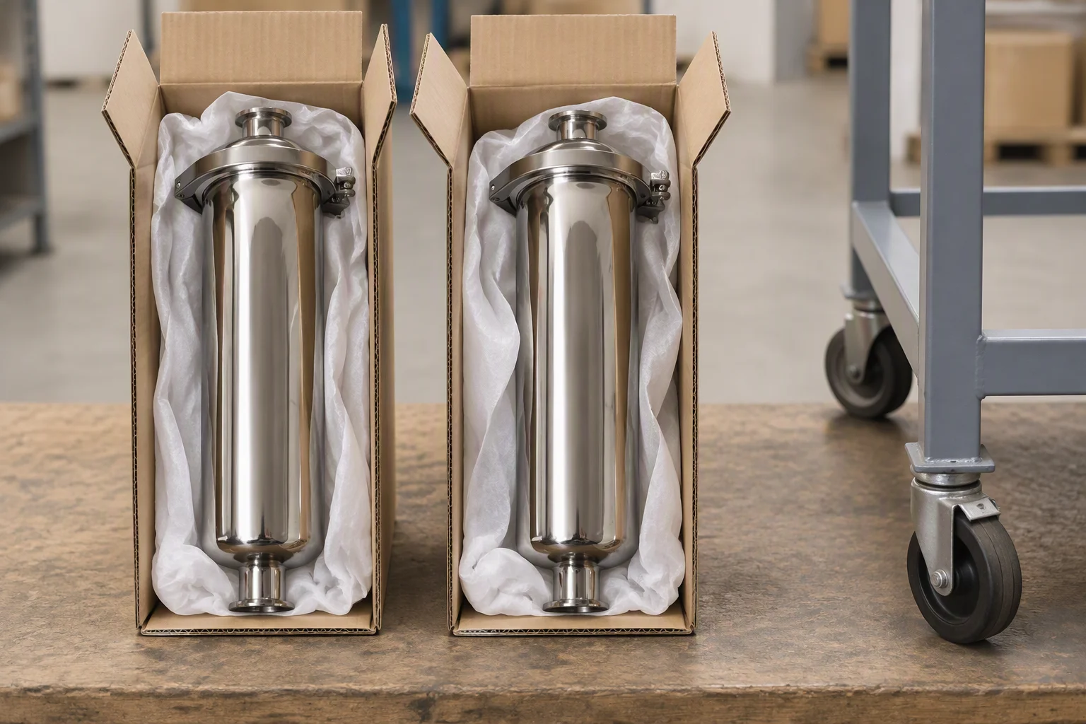
Two boxed elements standing on a bench next to the cart frame, each box open at the top with the element wrapped inside
FIG 14 ·

Elements ship boxed, off the cart. A fitted element travels with load on the pleats and nothing under it.

On this line · Fill and flush · Commissioning consumables · Filter housings · Fittings and seals

DOCUMENT REQUEST

Request the cart schedule

The cart schedule, the assembly drawing, both element ratings and the material certificate. Tick what you need.

If the form cannot send, this address takes the request instead: sales@ems-cool.com
The only promise on this page

One business day, with the file attached.

Nothing else on this sheet is promised. Price, stock and lead time are quoted against a request.
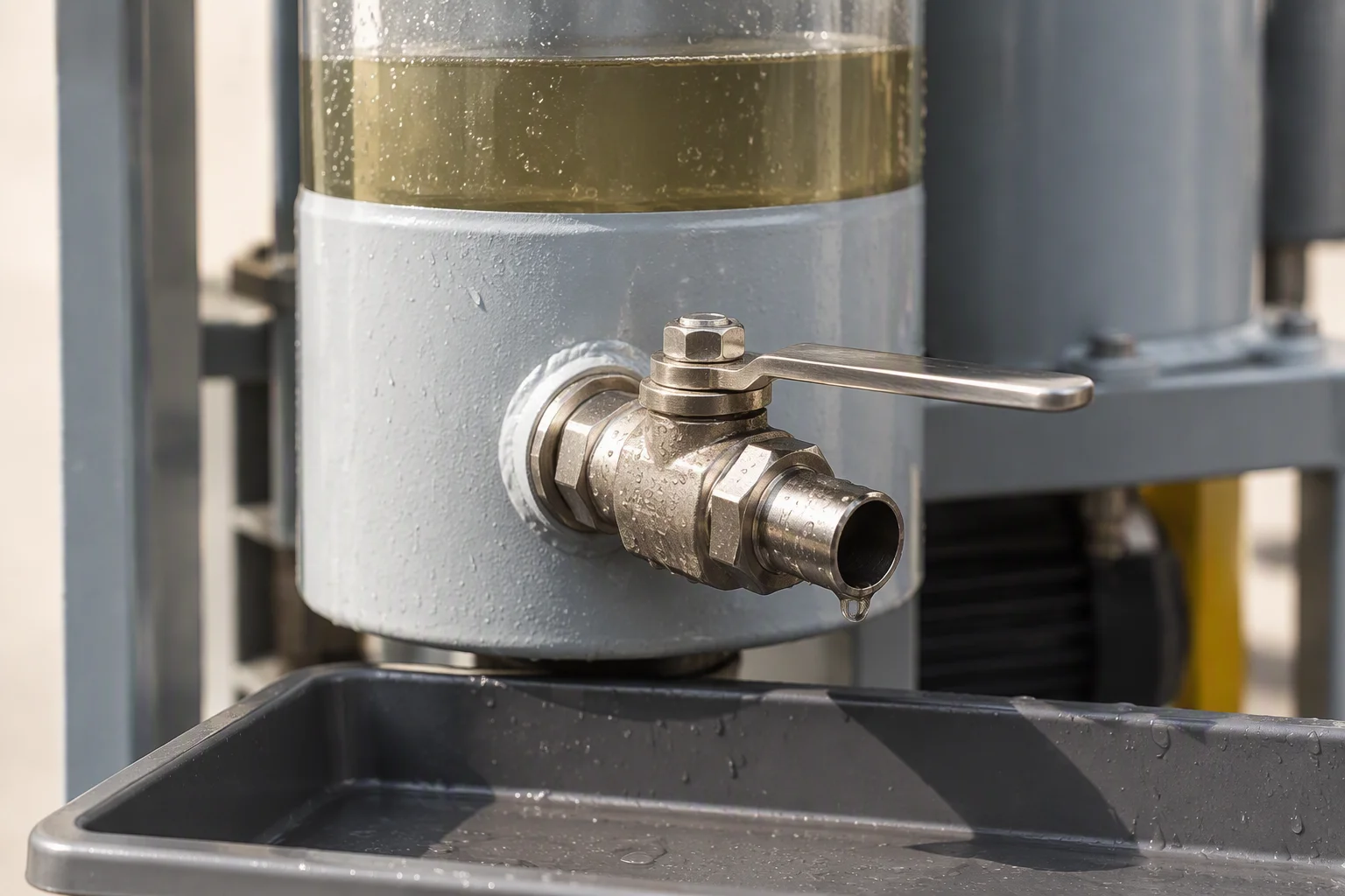
A bowl drain valve on a cart with a short outlet and a drip tray under it, the lever in the closed position and the bowl above it full
PL 01 ·

Drain valve per bowl. What comes out here is what the element took out, which is why the first drain is never the reading.
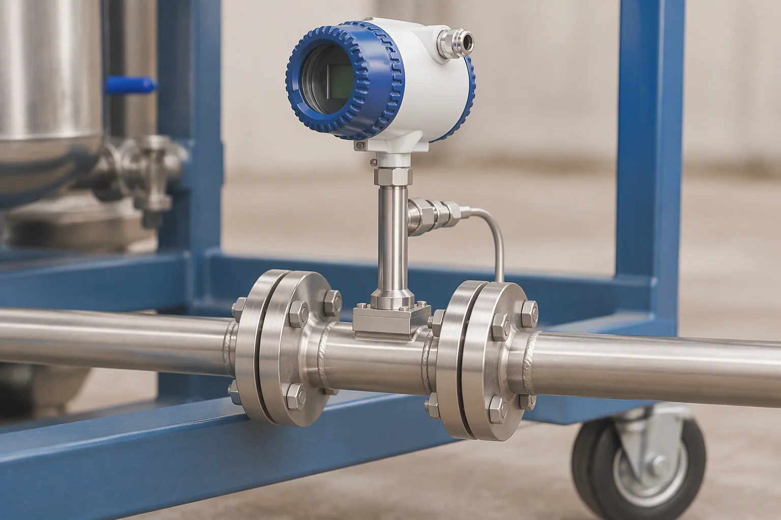
A flow meter mounted on a cart outlet with its face angled to the operator and no numbers legible on the dial
PL 02 ·

The meter is the second sizing figure read back: what the pump actually moves, against what the loop wants.