
Four judgements, and the figure each one turns on
Every guide below is written the same way: the rule for choosing a figure, and the second rule for what that choice costs you later. None of the four is about picking the best part. Each one is about picking the figure you can hold for the life of the loop.

Four subjects, one bench. Each guide on this sheet ends on the figure that decides between two of them.
The four guides
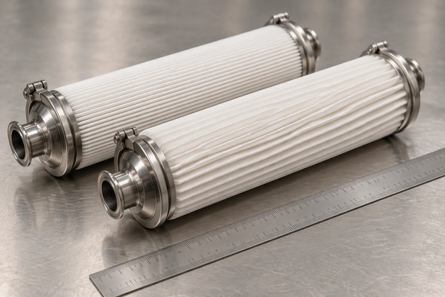
Rating · absolute against nominal, and where the ladder starts.

Interface · bond line against pump-out.

Cleanliness · the target, and where the sample comes from.
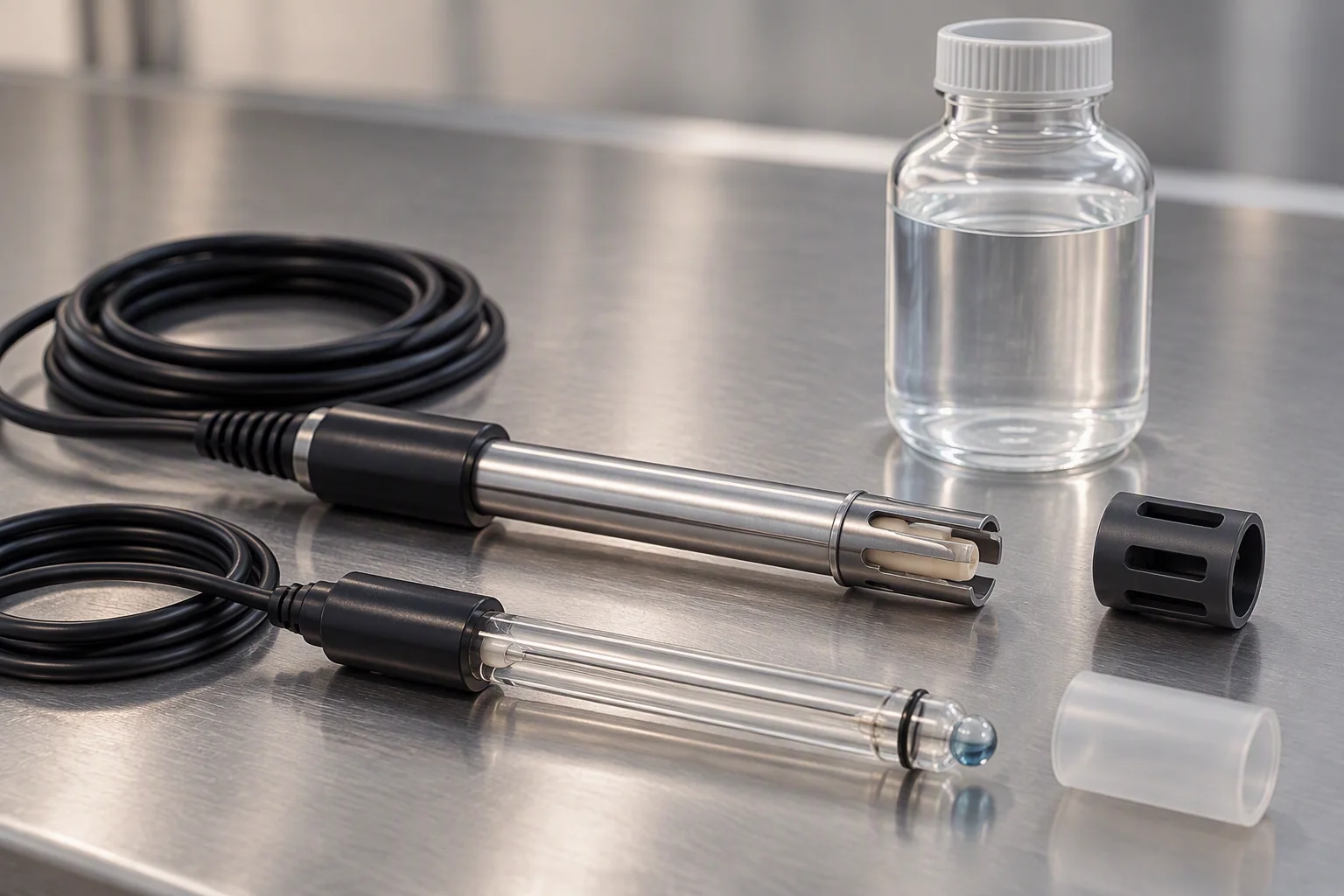
Water · the pair read together, never one alone.
Rating: choose absolute, and choose it once
A nominal rating describes an average opening; an absolute rating describes the largest particle that gets through. Only one of them can be written into an acceptance condition. The ladder runs 0.05 µm to 100 µm in eight steps, and the loop is normally quoted on two: a coarse stage that takes the load and a fine stage that holds the figure, with 1 µm absolute as the usual fine end.
Turns on 1 µm absolute · eight steps from 0.05 µm to 100 µm · elements in 20 in and 40 in, with 10 in on a small branch
Interface: the thickness decides the second year
A quotation states a conductivity figure, and the figure that decides whether the joint still works in year two is the bond line under it. Grease gives the thinnest line and is the first to pump out; a gap pad tolerates the tolerance and pays for it in interface resistance; a phase change material stabilises once it reaches its window; graphite sits at the top of the range and asks for flatness in return.
Turns on 1.0 – 15.0 W/m·K across four classes · grease 1.0 – 6.0 · pad 1.2 – 7.5 · phase change 2.0 – 8.5 · graphite 3.0 – 15.0 W/m·K through plane
Cleanliness: one target, three classes, one sample
The figure is written for the moment before the charge, and it is read as three code numbers at the same sampling rather than as an average. Where the sample is drawn decides what it says: a sample from the tank describes fluid that has not been round the loop, and it reads clean earlier than the loop is clean.
Turns on ISO 4406 17/15/12 · all three classes at one sampling · sampled on the return, upstream of the charge connection
Water: two readings that only mean something together
Conductivity moves when the inhibitor package is spent or when top-up water has got in; pH moves when the fluid itself has aged. Either one alone sends you to the wrong conclusion, which is why they are read on the same sample as the particle count. Glycol concentration is the third reading and the one most often skipped, and an elastomer responds to it within weeks rather than hours.
Turns on µS/cm and pH read together · glycol held at 20% or under in the facility supply
What the first two guides look like on the bench
The rating ladder is a physical thing: eight pleat densities, each one a different opening. Choosing a step is choosing how much surface area you are willing to pay for and how fast the element loads.
The change figure follows the choice: 0.5 – 0.7 bar across the housing, read from the clean-water zero the cart was run to before it shipped.

The ladder as stock. Two steps of it go into a loop; the other six exist so the two can be chosen rather than inherited.
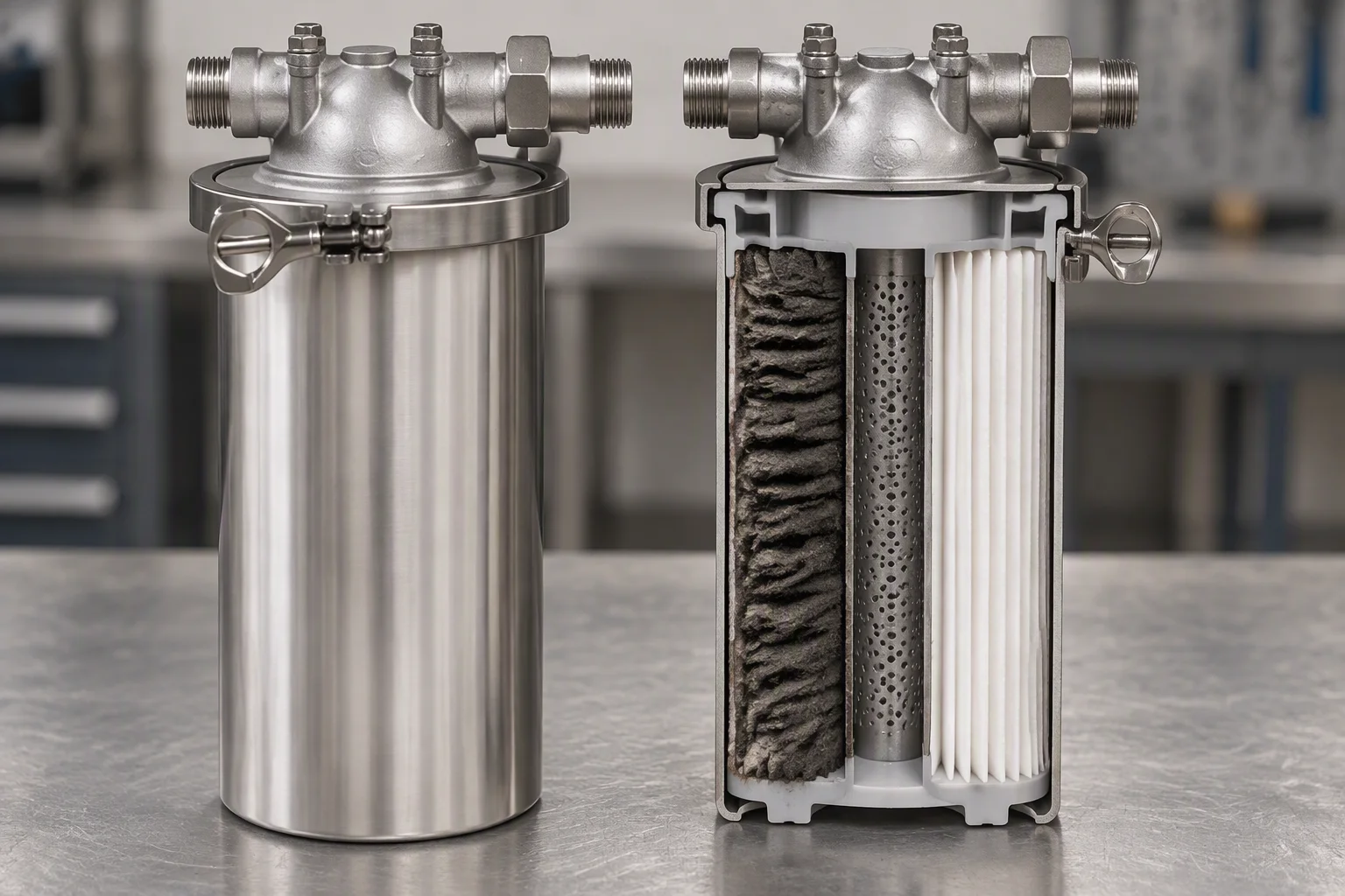
What loading looks like from the inside. The outer face takes it, which is why the differential is read rather than looked at.
The four interface classes, on the same bench. Thickness is the property none of them is quoted on and all of them are judged by.

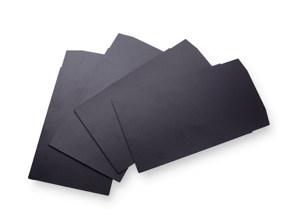

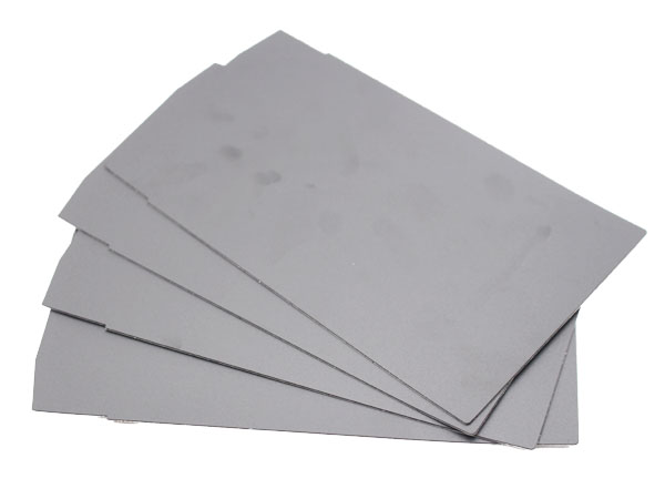
Every sheet in this strip is a photograph of the article, not a rendering. The dimensions that matter are the ones a rule can be laid against.
What the last two guides look like on the bench
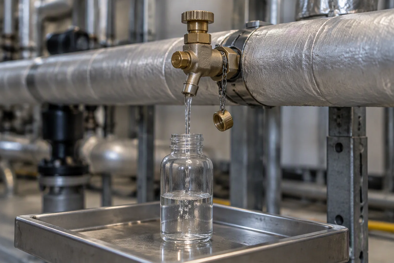
Where the sample comes from. Change this and the code number changes without a thing being done to the loop.
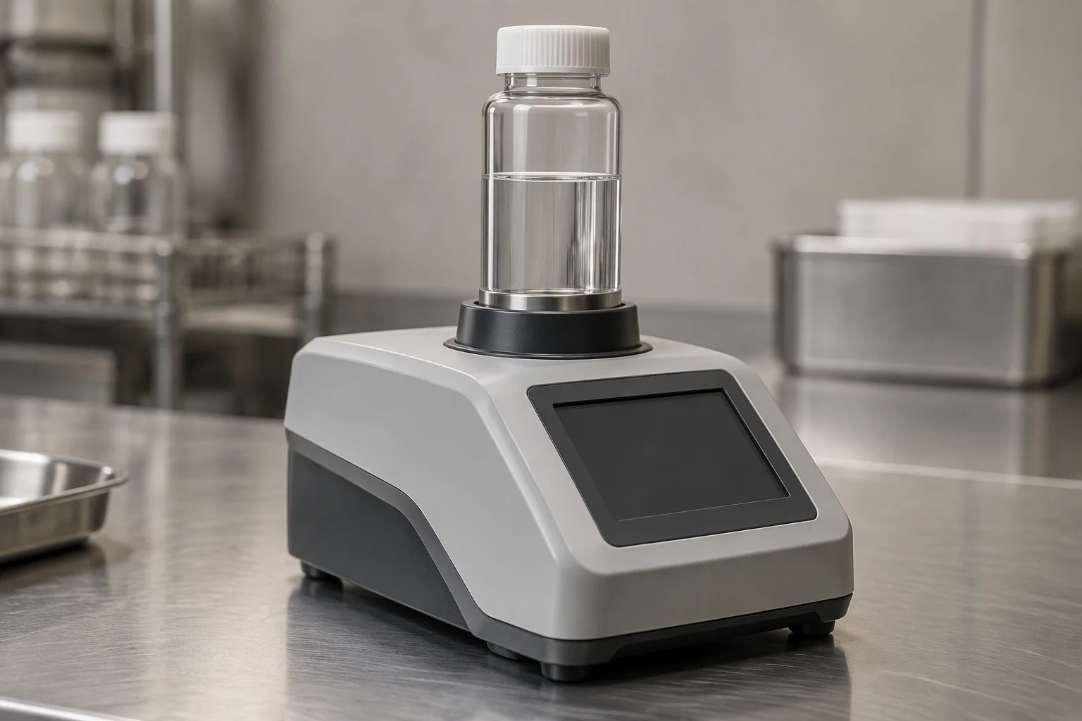
Read on the spot, at three classes, once. A sample that travels has had time to settle and reads better than the loop is.
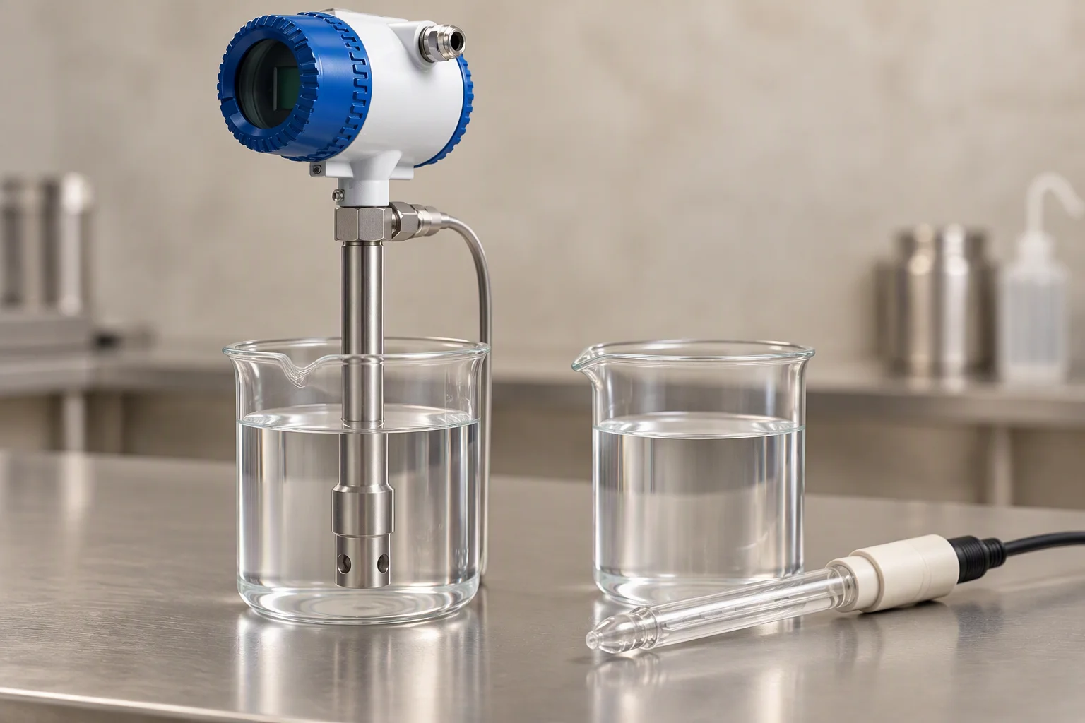
Two readings, one sample. Conductivity without pH tells you the fluid changed and not which way.
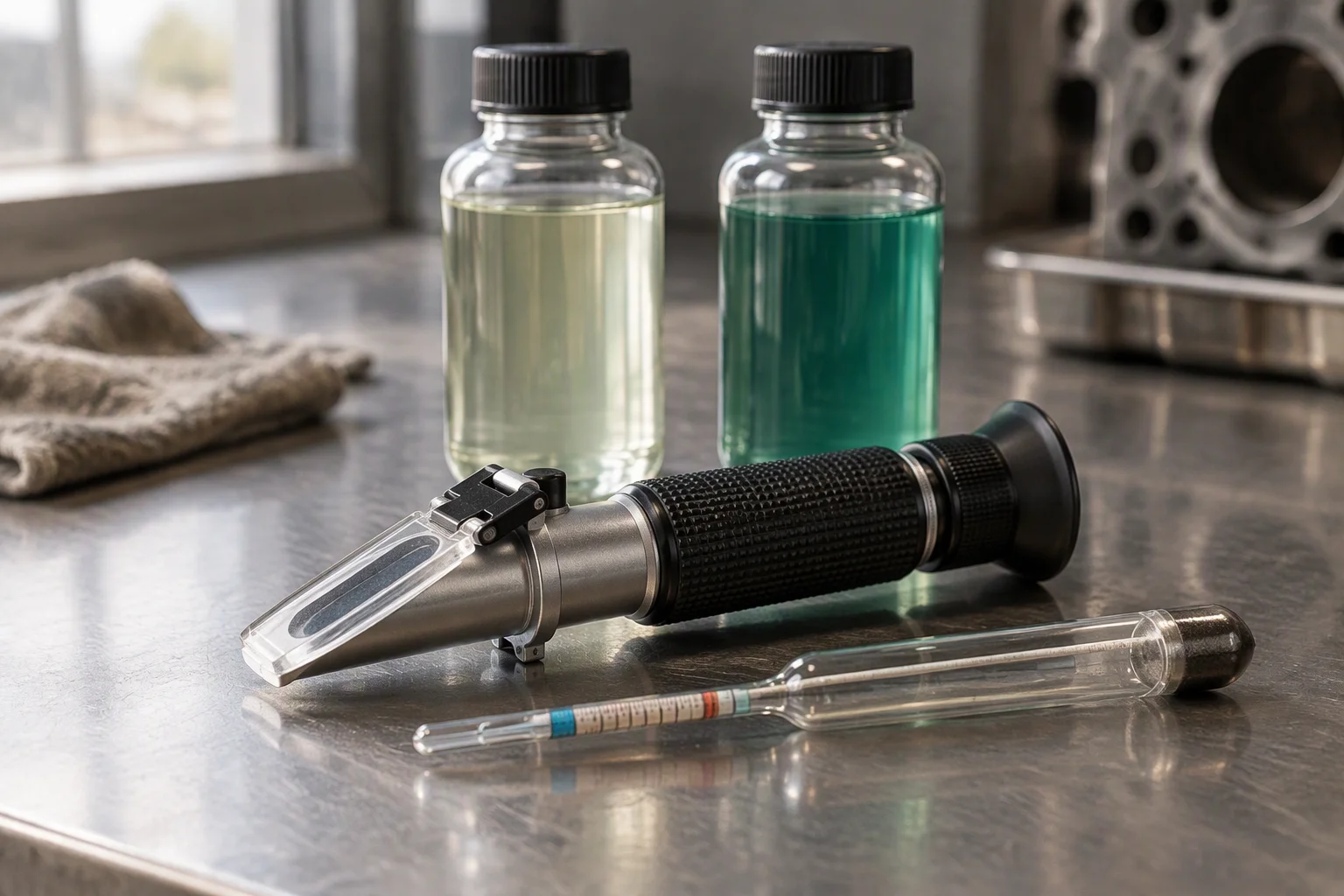
Two bottles of the same coolant at two concentrations. The elastomer reads the difference even when the loop runs the same.
How each of the four is misused
Done on the order as written
- Two stages, coarse then fine, each on its own change rule.
- Absolute rating written into the acceptance condition, not nominal.
- Bond line stated with the conductivity figure, on the same line.
- Cleanliness written as the target at the charge, with the sampling point named.
- Conductivity and pH read on the same sample, with the glycol figure beside them.
Done short, and what it costs
- One stage, run to a single rating: it takes the load and passes the fine particles while it does.
- Nominal rating quoted: the acceptance condition cannot be checked at the bench.
- Conductivity alone: a figure that satisfies the quotation and fails in the second year.
- Sample drawn from the tank: clean earlier than the loop is.
- Glycol concentration assumed from the drum label: the elastomer finds out first.
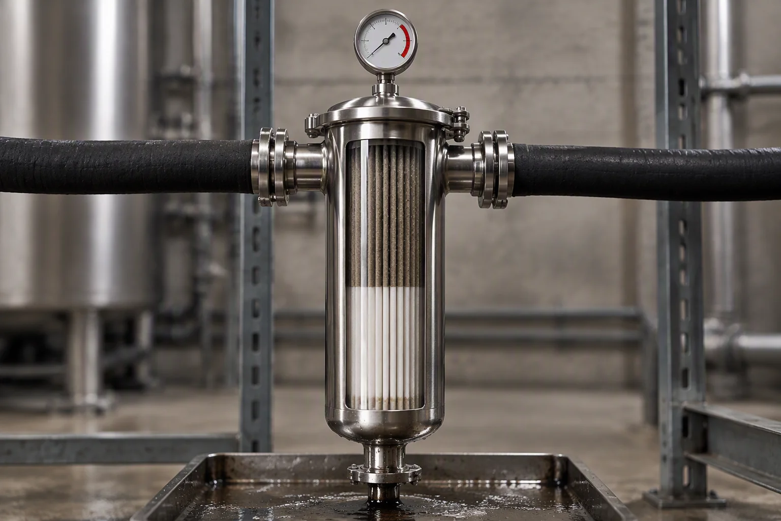
One stage. It is not wrong until the differential climbs, and then it is wrong for every hour after.
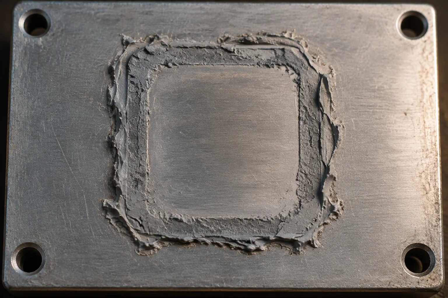
Pump-out. The figure on the quotation was right and the print of the die is where the material used to be.
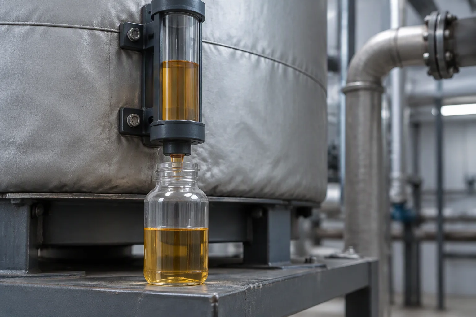
Sampled in the wrong place. The bottle is clean and the loop is not, and both are recorded as passing.
Request the four guides
The rating ladder, the interface comparison, the cleanliness target and the water chemistry pair, each on one page with the figures behind it.
One business day, with the file attached.
Nothing else on this sheet is promised. Price, stock and lead time are quoted against a request.
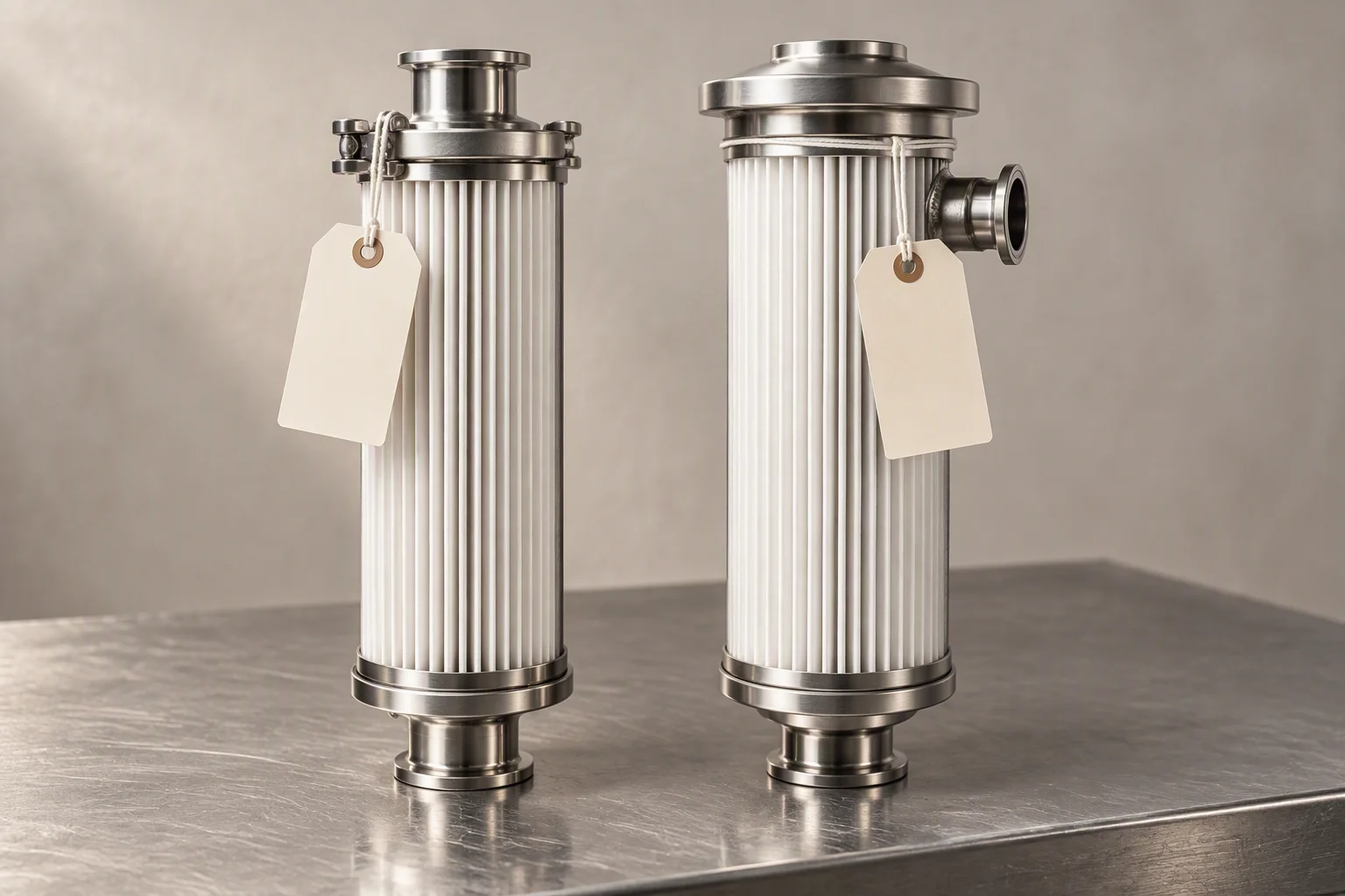
Two options, one decision. The guide is written to make the decision take one reading rather than a meeting.

The figure that gets written down is the one that can be checked later. Everything on this sheet is written to be that figure.
