EMS-Trade
Cooling
Loop consumables

Document ECT-01 · REV C · ISSUED 2026-09 Six lines · 48 sheets

Sheet 06-1 · Telemetry · flow instruments

Flow instruments for the liquid cooling loop

A flow reading is worth what the meter's position is worth. This sheet puts the meter on the loop first, then gives the line sizes it has to match and the parts it has to work between.
Line size DASH −4 to −10 Bore 6.1–15.8 mm Output 4–20 mA Loop pressure 1.38 MPa

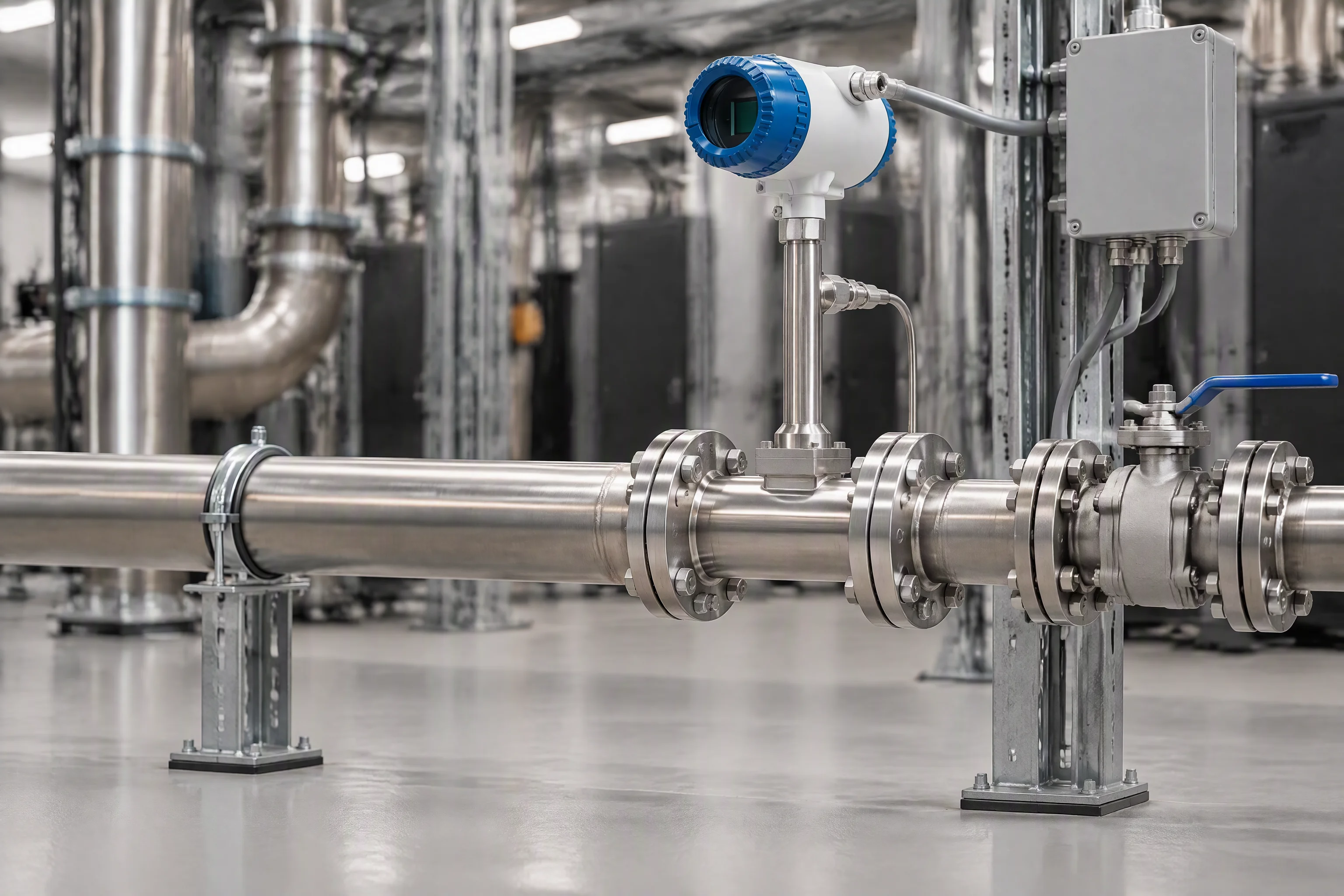
An in-line flow meter flanged into a horizontal stainless run above a plant room floor, with a straight pipe length upstream, a valve downstream and a junction box on a bracket beside it
FIG 01 · The straight length upstream is part of the instrument, not part of the pipework.
01

Where the meter sits on the loop

Section 01 · position · upstream and downstream marked

A meter reads the flow through its own bore, not through the loop. Put it after a bend, a valve or a strainer and the number wanders with the disturbance rather than with the flow. Every instrument here is ordered with the straight length it needs, and that length is what a site has to leave for it.

The useful position is usually the branch, not the header. A header reading tells you the loop is moving; a branch reading tells you which branch stopped moving, and that is the one that ends in a hot spot.

One branch of the loop, from the supply header to the return header, with the flow meter's position marked Supply header on the left, then an isolation valve, a strainer, the flow meter in a straight run, a branch take-off, a filter, and the return header on the right. Supply valve strainer flow meter 01 straight length both sides branch filter 02 return one branch of six, read on its own

Key

  1. 01The meter goes in the straight length, downstream of the strainer and upstream of the branch take-off.
  2. 02The filter sits after the meter, so a loading element does not change what the meter reads.
FIG 02

Valve, strainer, meter, take-off. Order matters more than the instrument does.
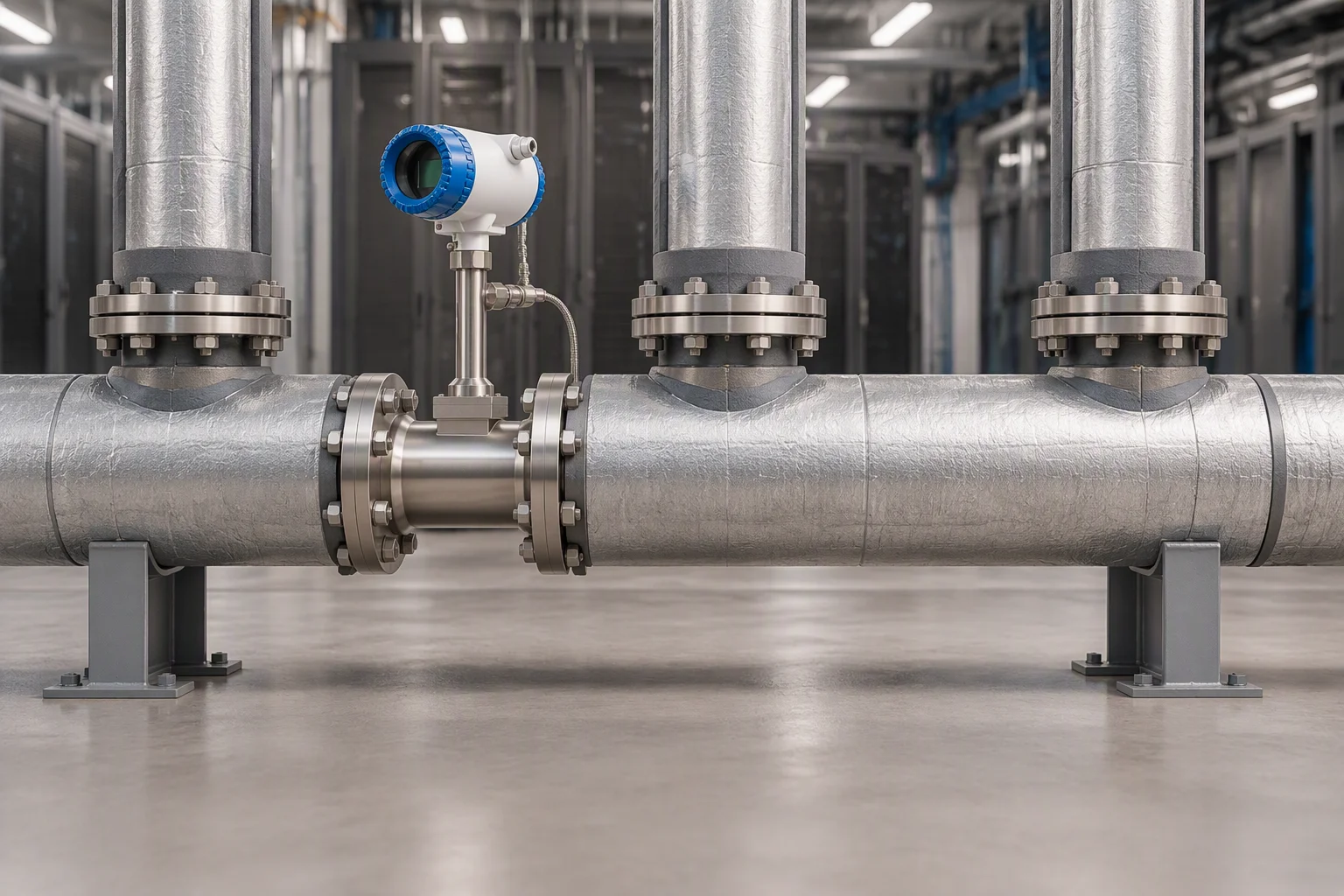
A supply header with three branch take-offs and a flow meter flanged into the run, the branches leaving upward towards the racks
FIG 03

A header reading is a total. It tells you the loop is moving, not where it stopped.
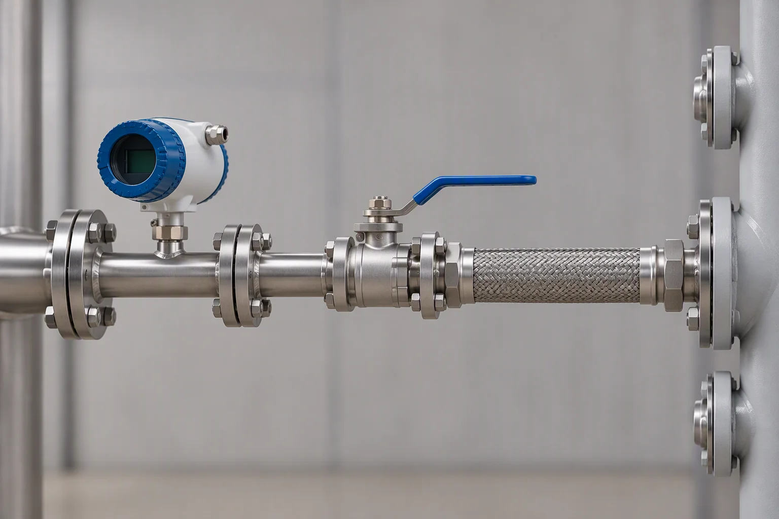
A single branch line leaving a header with a flow meter in it, a valve downstream and a flexible connector into a manifold
FIG 04

A branch reading names the branch. That is the one worth paying for.
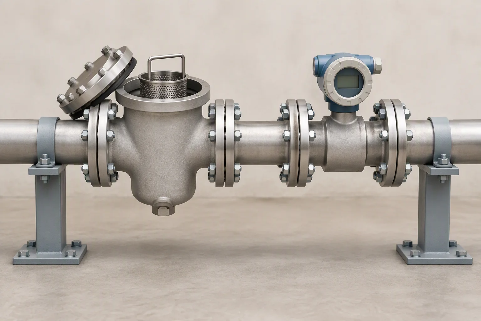
A basket strainer in a run with its cap loosened and a flow meter flanged downstream of it in the same straight length
FIG 05

The strainer goes upstream, so the meter's bore keeps its geometry.
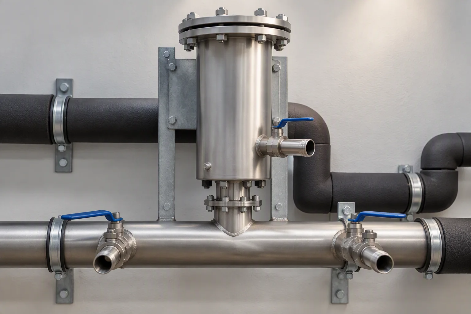
A return header with two branch connections and a filter housing mounted on a bracket above the run, insulated pipework below
FIG 06

On the return the meter sees the filter's loading. Which is a reading, but not the one you wanted.

Read next · Telemetry · Hose & piping · Filter housings

02

Line size, bore and the pressure behind it

Section 02 · interface · the table the order is placed from

Flow instrument interface · line size, bore, output and the loop conditions it holds
Item End of the range Value Note
Line size Smallest DASH −4 Branch lines and short runs to a single rack
Line size Largest DASH −10 Headers and long runs to a plant room
Bore At DASH −4 6.1 mm Inside diameter; the meter is ordered to it, not to the outside
Bore At DASH −10 15.8 mm Inside diameter; sizes between the two ends are ordered to the run
Output Analogue 4–20 mA One loop per reading, into a current input card
Output Bus Modbus RTU Where the site already runs a pair to the panel
Working pressure Loop 1.38 MPa The body is ordered to hold the loop, not the pump's shut-off head
Media temperature Loop −40 to +99 °C The range the wetted parts and the seals are ordered against
Wetted metal Certificate EN 10204 3.1 Per batch, on the metal parts that see the coolant

The two ends of the range · the line sizes between DASH −4 and DASH −10 are ordered to the run, and the specification sheet lists every one of them with its bore. Nothing here is quoted as a range you have to ask about again.
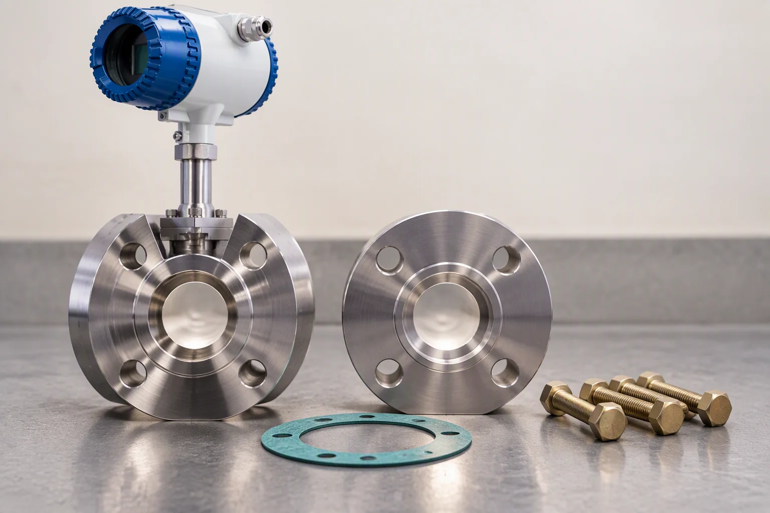
A flanged meter connection on a bench beside its mating flange and gasket, with the bolt holes lined up and the pipe bore visible through both
FIG 07

A flanged pair on a bench: the bore is visible, so the size is checked before the order goes out.
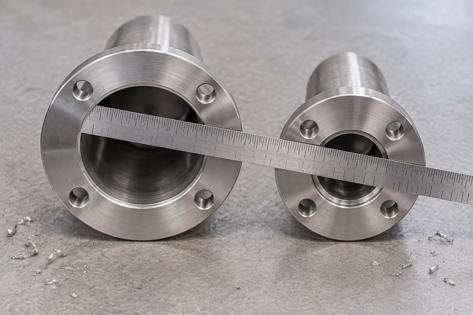
Two pipe ends of different bore laid side by side on a bench with a rule across them, showing the inside diameters against the scale
FIG 08

Bore, not outside diameter. It is the one dimension the reading depends on.

Read next · EPDM hose · Fittings & seals · Design guides

03

What sits either side of the meter

Section 03 · the pair · these two decide whether the reading holds

Upstream is the strainer: it protects the bore from the debris a loop sheds in its first months. Downstream is the filter: it takes the loading the strainer was never sized for, and its differential climbs towards 0.5–0.7 bar over the life of the element. Read together, the pair tells you whether the loop is clean and whether the element is finished.

One strainer, one filter, one meter between them. All three ordered to the same bore.
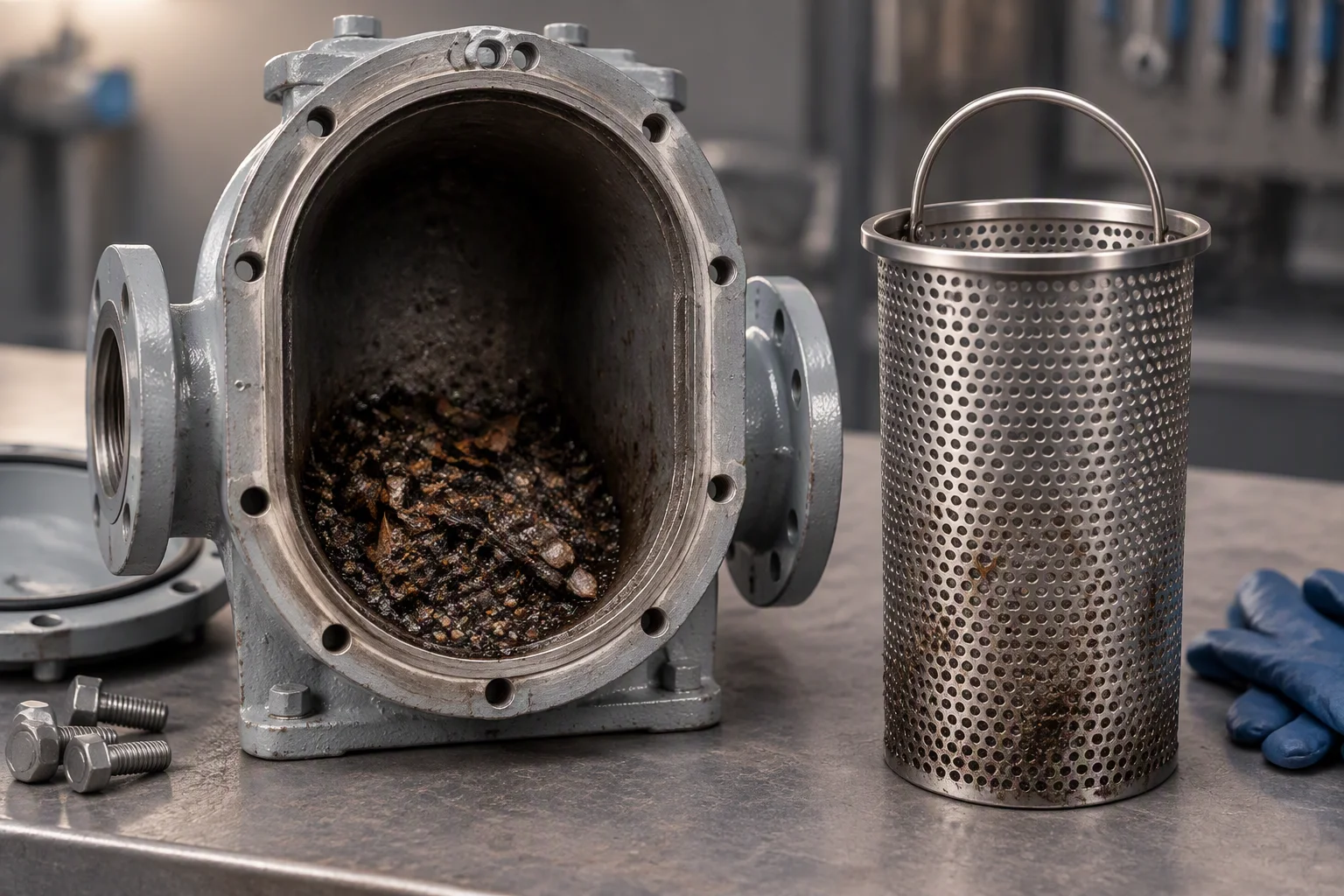
Upstream
a basket strainer, so the meter's bore keeps the geometry it was calibrated in
Downstream
a filter housing, changed out when the differential reaches 0.5–0.7 bar
Cleanliness target
ISO 4406 17/15/12 before first power-on, with filtration down to 1 µm absolute
Straight length
both sides of the meter, ordered with the instrument and left by the installer
Couplings
dry-break quick couplings where a section has to come out without draining the loop
A basket strainer opened on a bench with the basket lifted out and the debris it caught sitting in the base of the housing
FIG 09

What the strainer caught is the first month of the loop's life.
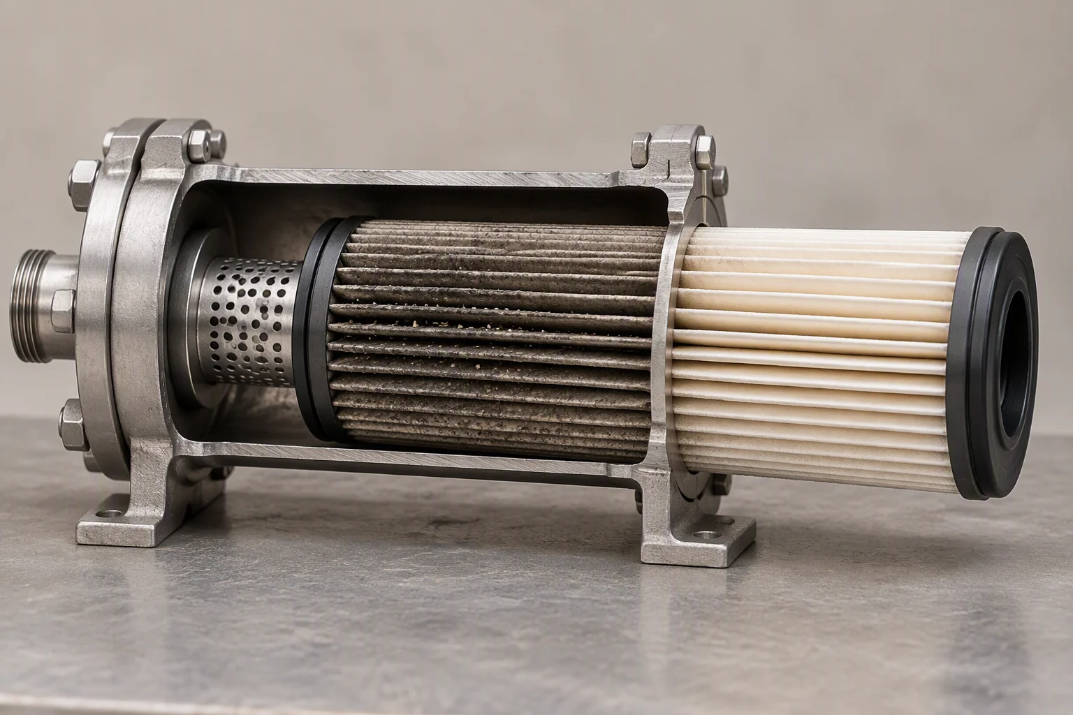
A filter housing cut open on a bench with a loaded pleated element drawn part way out, the pleats darker on the upstream face
FIG 10

A loaded element is a differential, and the differential is the change-out signal.

Read next · Filter cartridges · Quick disconnects · Fluid quality monitoring

04

The parts, photographed

Section 04 · four parts · as shipped

Four parts, photographed on the bench rather than rendered. What is on the pallet is what is in the photographs: no rendering is used for a part that a buyer has to fit.
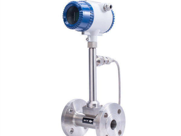
Flanged in-line flow meter with a blue-capped transmitter head on a stainless body, photographed on a white ground
PL 01 Flow meter, flanged Stainless body · local indicator · 4–20 mA
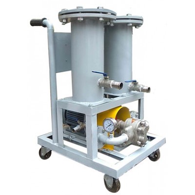
A filter trolley on a wheeled frame: two grey cylindrical housings with flanged tops, blue-handled ball valves, a pump below and a round gauge on the outlet
PL 02 Filter trolley Two housings · gauge · bypass valve
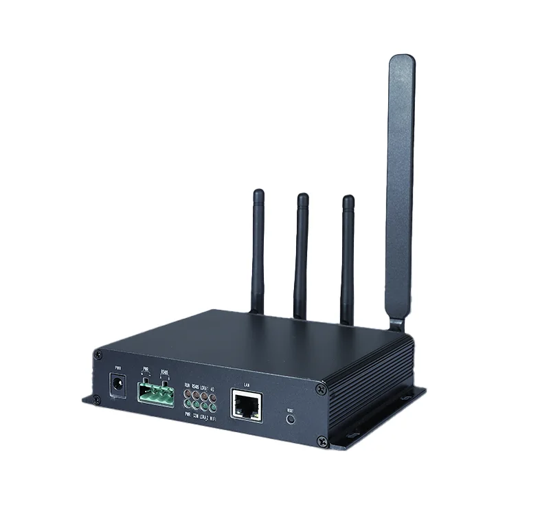
Black finned gateway with four antennas, a green screw terminal block, a LAN port and a DC power socket along its front edge
PL 03 Gateway Terminal block · LAN port · four antennas
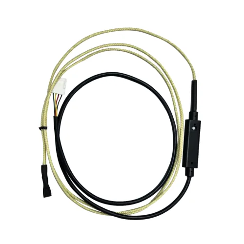
Beige braided sensing rope coiled on a white ground with a white plug at one end and a black in-line module part way along it
PL 04 Sensing run Cut to length · terminated before packing

Read next · Quality & inspection · Supply network · Projects

05

The documents that travel with the shipment
Section 05 · documents · per shipment and per batch

Certificates
EN 10204 3.1 on the metal parts that see the coolant
Inspection
incoming inspection record per batch, kept with the batch number
Drawings
outline drawing per size ordered, at the same line size as the meter
Declaration
CE marking on the electronics, RoHS and REACH on the materials, ISO 9001 behind the batch record
Commercial
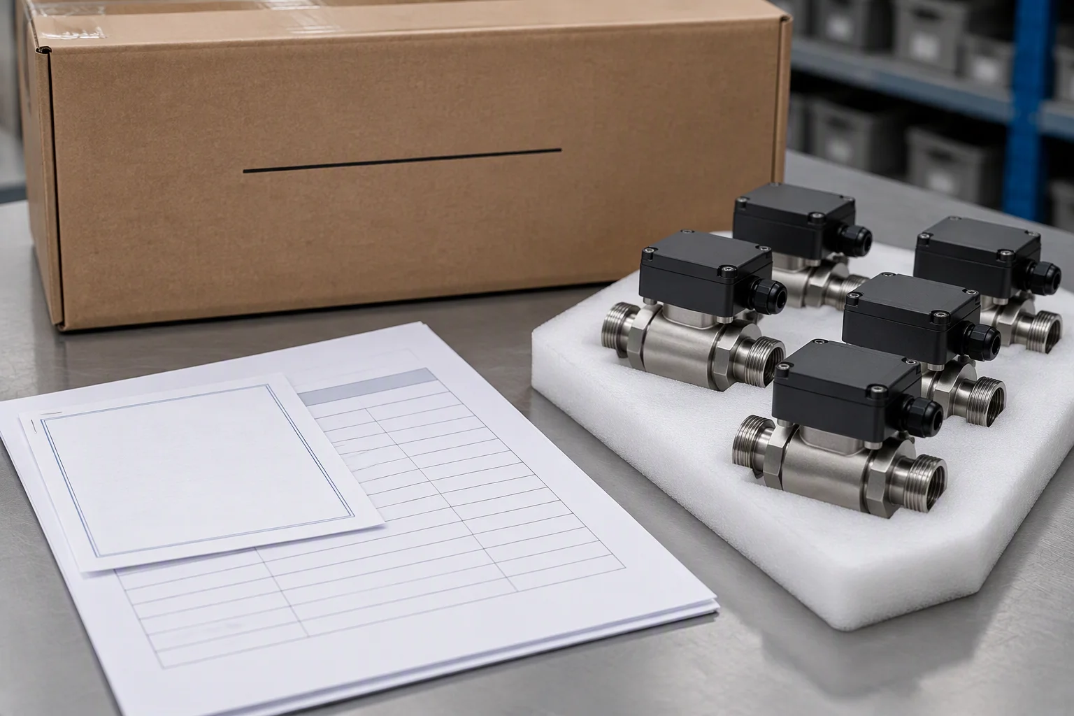
packing list, invoice and certificate of origin, in English
A batch record on a bench beside the parts it covers, the certificate stapled to it and the batch number written on the carton behind
FIG 11

The batch record and the carton carry the same number, which is the point of both.
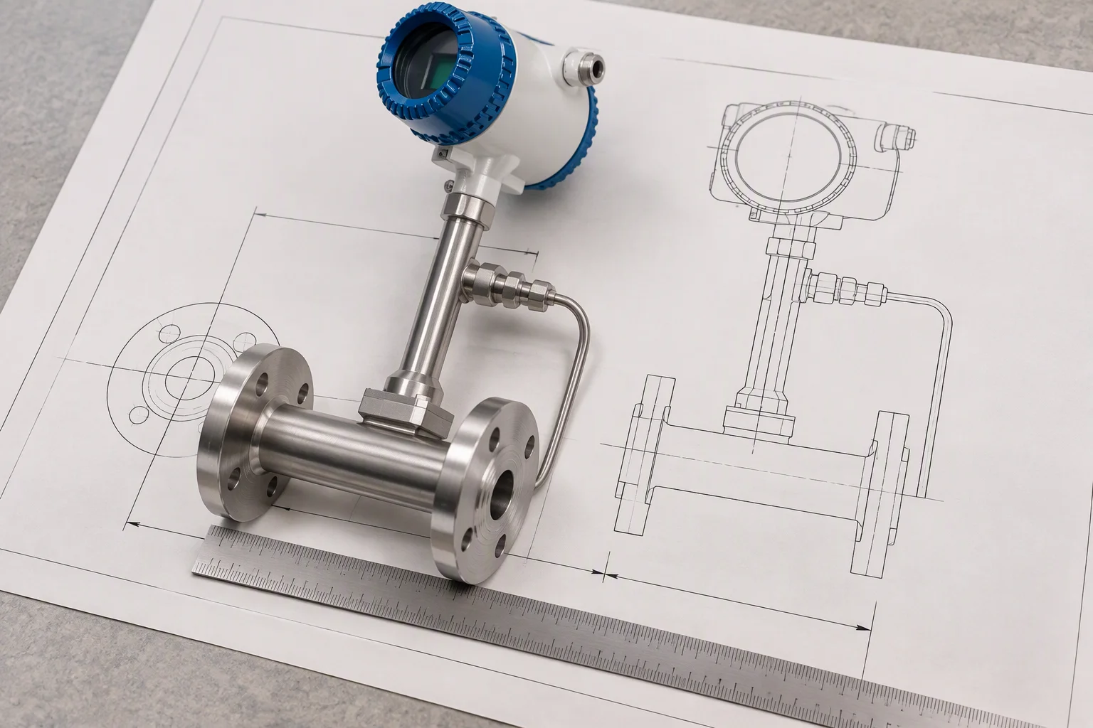
An outline drawing on a bench with a rule across it and the meter it describes laid on the drawing, the flange centres lined up with the marked dimension
FIG 12

Drawings are issued at the size ordered, so the flange centres can be checked against the run.

Read next · Quality & inspection · FAQ · Contact

Document request

Four documents are held for this sheet. Tick the ones you need.

Tick a document, give the line size and the quantity, and the file comes back attached.

The only promise on this page

One business day, with the file attached.

Nothing else on this sheet is promised. Price, stock and lead time are not promised here.
If the form cannot send, the address below takes it instead: sales@ems-cool.com. A request is never accepted and then dropped.
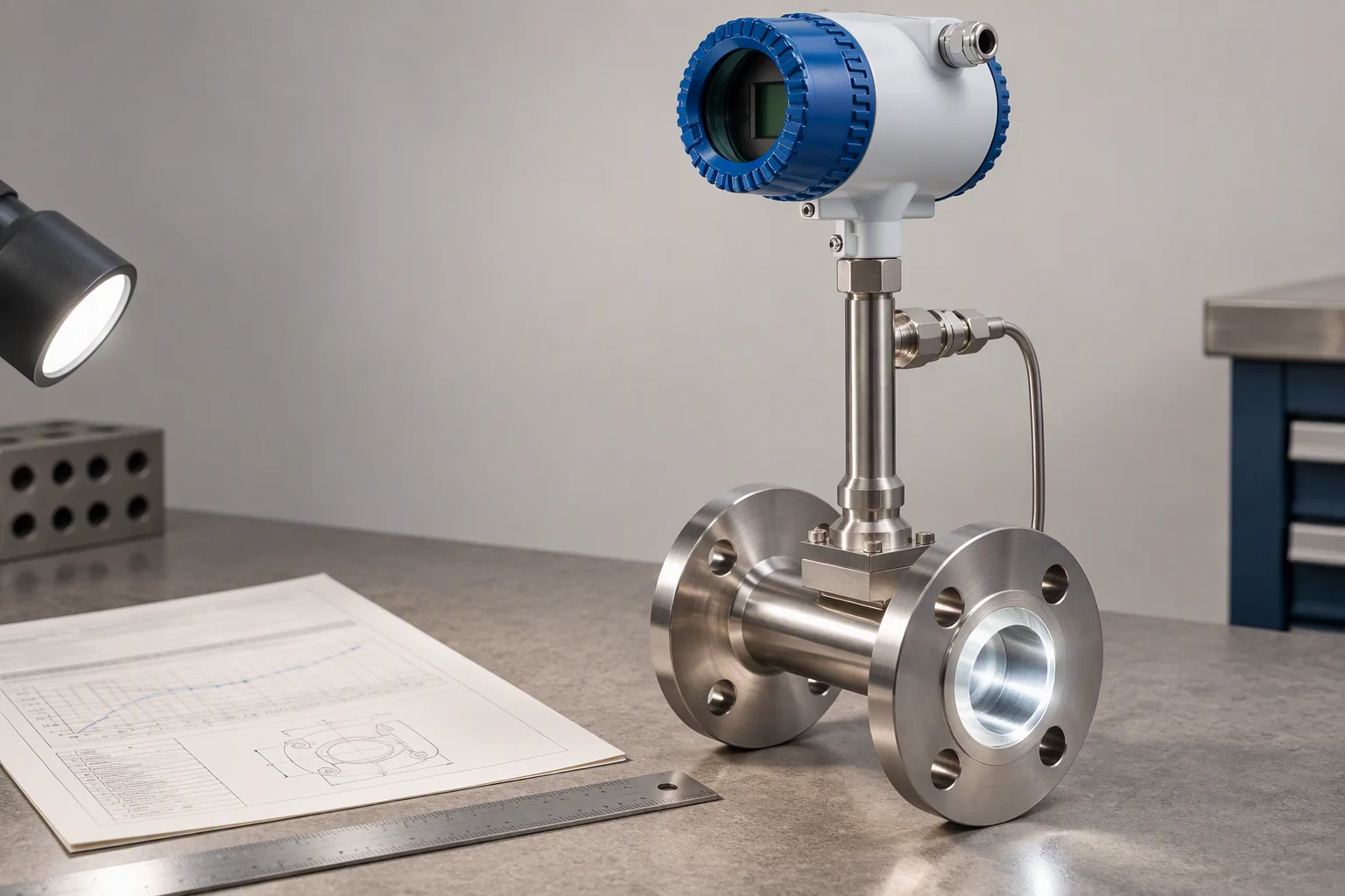
A flow meter on an inspection bench with its certificate beside it, a rule across the flange face and the bore lit from the side
FIG 13

Checked at the bench before it goes in the carton, at the size that was ordered.
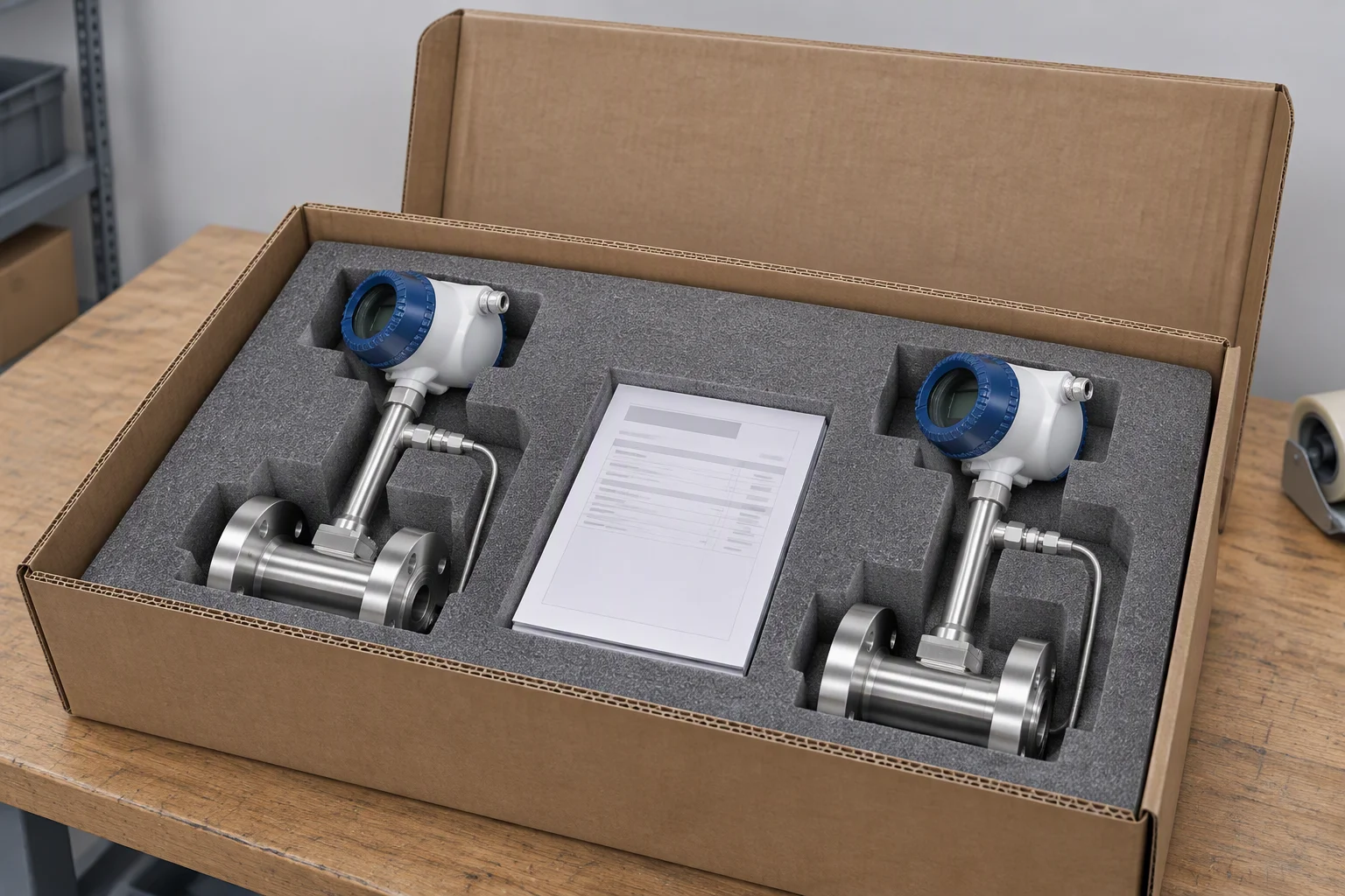
An open export carton with foam cut to the shape of two meters, the parts seated in it and a packing list laid on top of the foam
FIG 14

Foam cut to the part, not loose fill. A meter that arrives out of true is not a meter.