
Telemetry for the liquid cooling loop
The loop is watched on five readings, taken at five different places. This sheet is the index to them: the reading, the instrument that takes it, the way it leaves for the building management system, and the baseline it has to be compared against before it means anything.
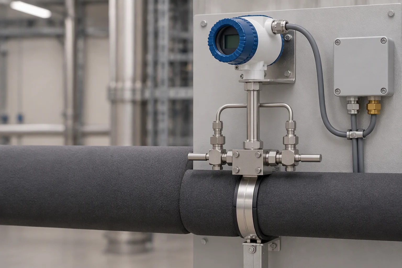
Readings are taken where the loop bends, not where the desk is.
The readings, and the failure each one is watching
A loop runs for years at a set point, and almost nothing on it fails loudly. Coolant chemistry drifts, an element loads up, a joint weeps into the floor void. Each of those moves a number before it becomes a fault, which is the whole argument for instruments.
Five readings cover that ground: supply and return temperature, flow, differential pressure across the filter, level in the reservoir, and the leak position. Conductivity and pH belong to the same line and are carried on their own sheet, linked at the foot of this one.
| Reading | Instrument | What it tells you | What it prevents |
|---|---|---|---|
| Supply and return temperature | Resistance thermometer in a thermowell | Whether the loop is still moving heat, and by how much | A cold plate starved of flow, misread as a supply problem |
| Flow | In-line flow meter | Hydraulic balance between the branches on one header | A pump run against a closed valve |
| Differential pressure | Transmitter across the filter | How loaded the element is, in bar | Flow starvation, and the hot spot behind it |
| Level | Level sensor in the reservoir | Make-up rate, which is a leak rate with a delay | A reservoir drawn down to the pump inlet |
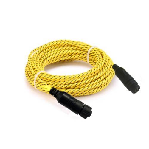
| Leak position | Locating sensing rope | Where the water is, to 0.1 m along the run | A wet tile three rows from the walk-round |
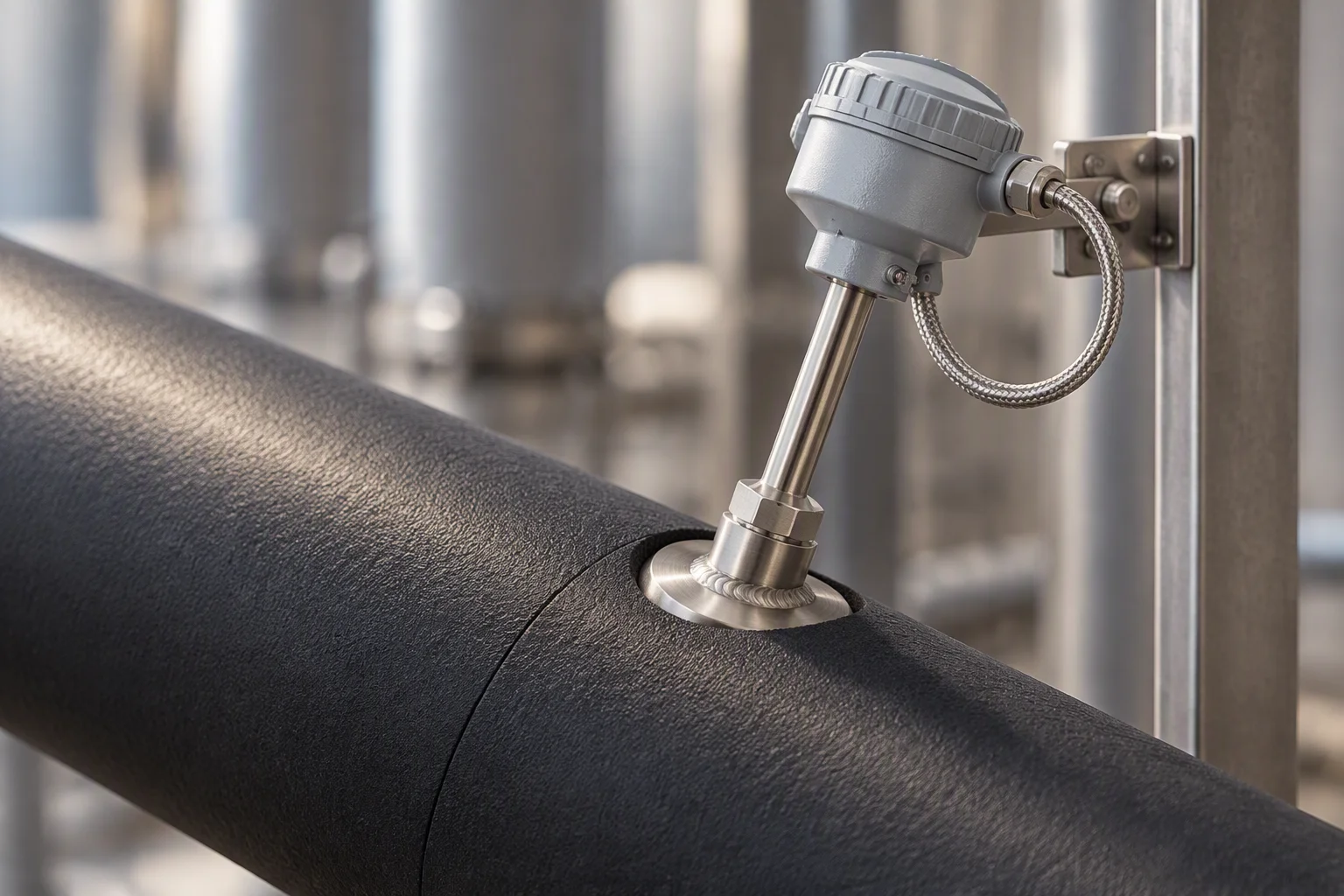
A thermowell puts the element in the flow without putting the joint in it.
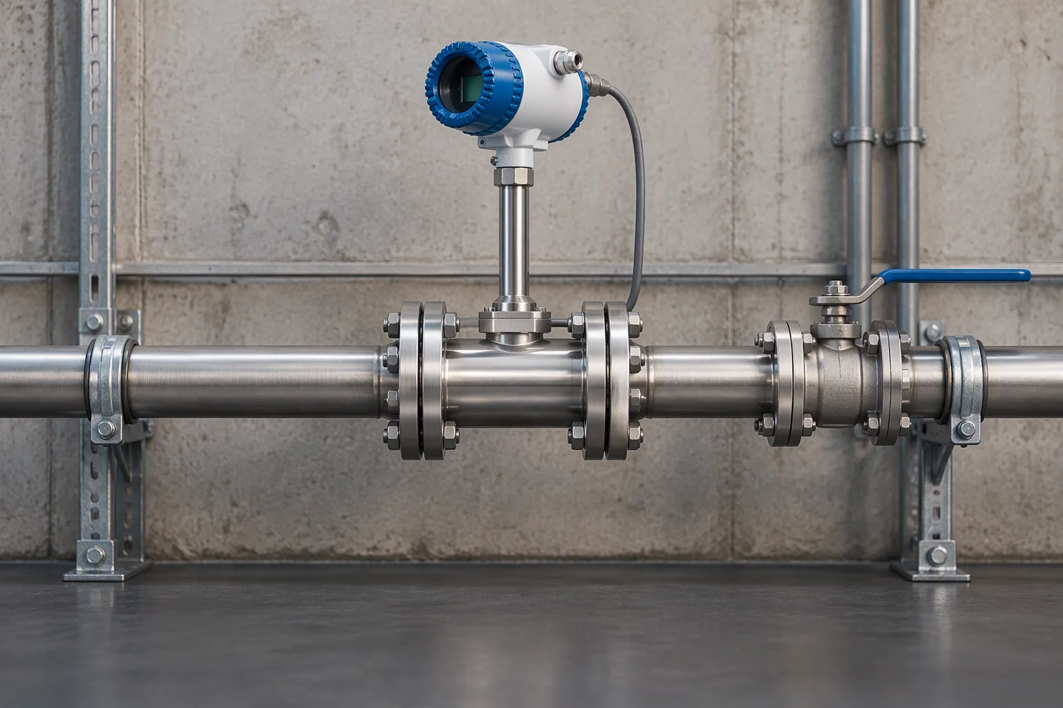
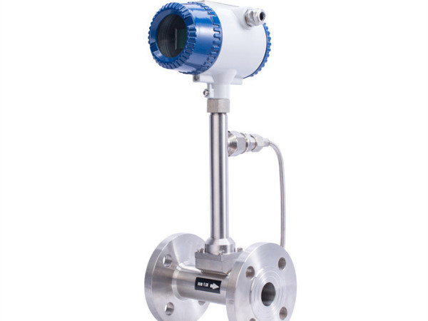
The straight length upstream is not decoration: it is what makes the reading repeatable.
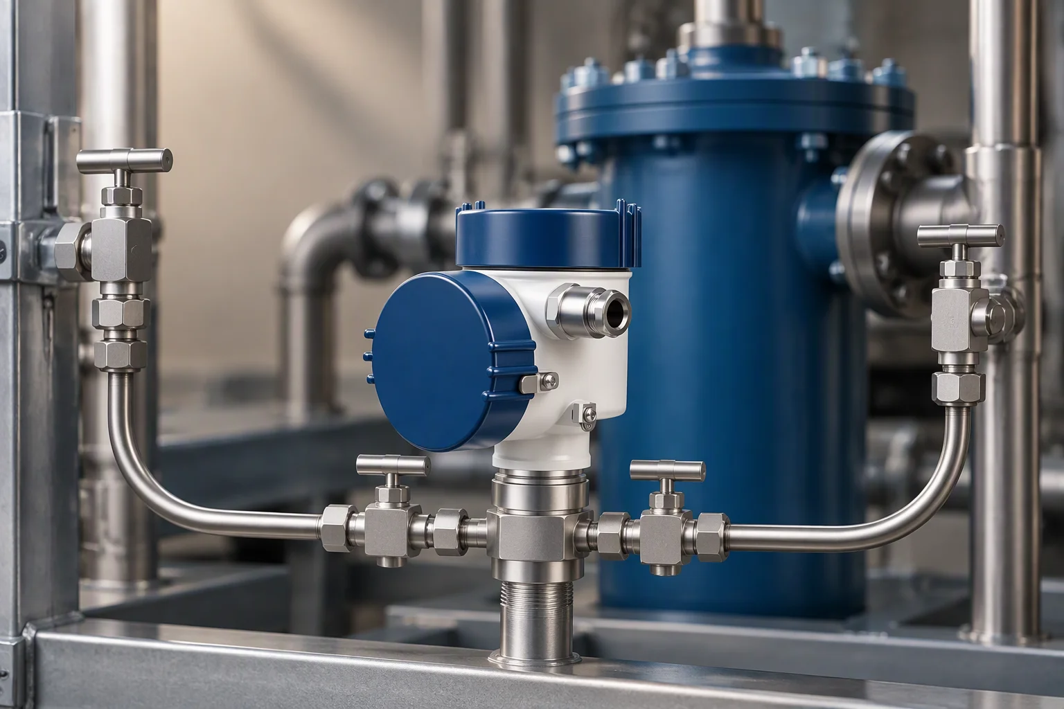
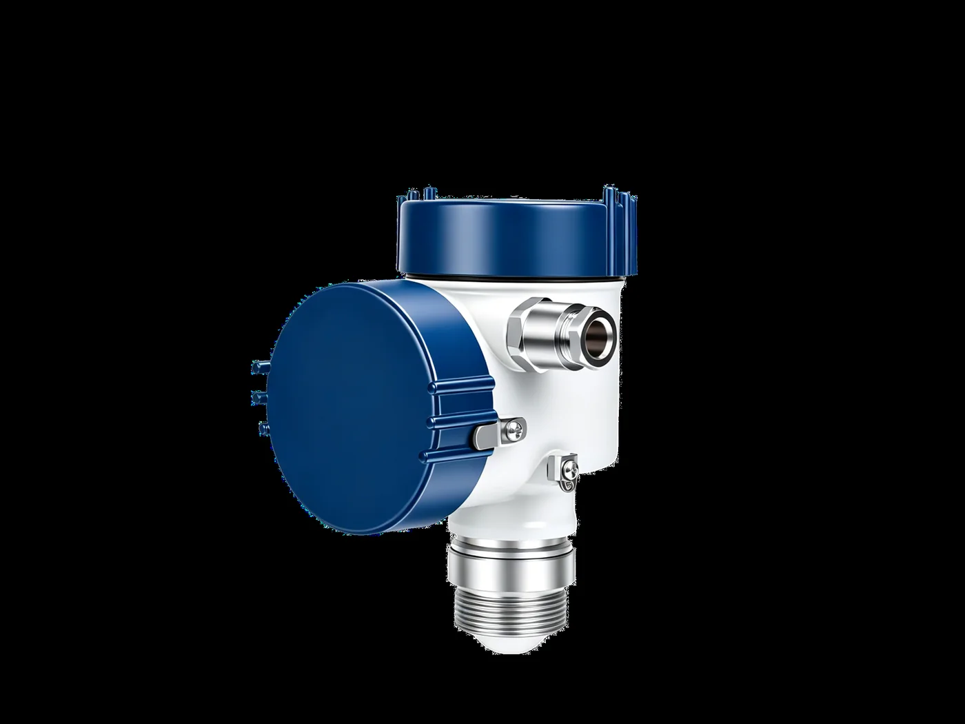
Two tappings, one either side of the element, and the difference is the reading.
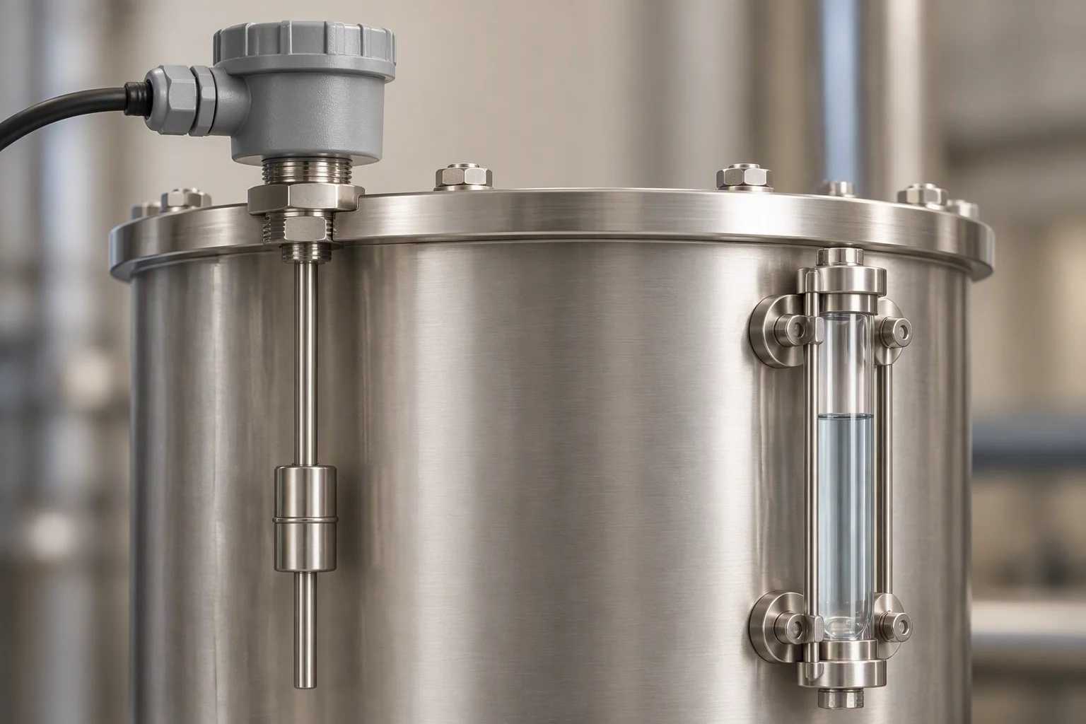
Level is the slowest reading on the sheet and the one that runs out of time first.
Read next · Flow instruments · Pressure instruments · Fluid quality monitoring
The instruments, one mount per reading
A reading seldom arrives as a number. It arrives as a current, a resistance or a relay that opens, and something at the tapping point has to turn it into a signal a long cable can carry without drifting. That conversion is what a transmitter is for, and it is why the reading is taken at the tapping point rather than at the panel.
Differential pressure is the one that earns its place first: it moves before any of the others do.
Level is second, because a reservoir that is going down has already decided the rest of the day.
Read next · Coolant filtration · Leak detection · Quality & inspection
How a reading reaches the building management system
An indicator on the wall is not telemetry. A reading becomes telemetry when it reaches the system somebody already watches, and that system decides the path. Most sites run one of the three below; a site running all three gets a bus reading, a volt-free contact for the local panel, and an analogue loop for a PLC.
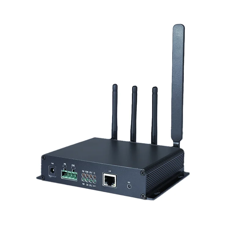
The three paths are not alternatives to be ranked. Modbus RTU carries the number, the dry contact carries the alarm, and the 4–20 mA loop carries the value into plant that has no bus at all. A gateway converts between them where the cable run cannot reach.
Key
- 01Five readings, five transmitters, each one converting at its own tapping point.
- 02One gateway carries them, and gives each reading its own address.
- 03Three paths out: a bus, a volt-free contact, and an analogue loop.
Readings on the left, the paths out on the right. One of the three leaves the room.
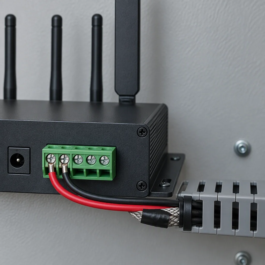
Modbus RTU: two wires and an address set at the gateway.
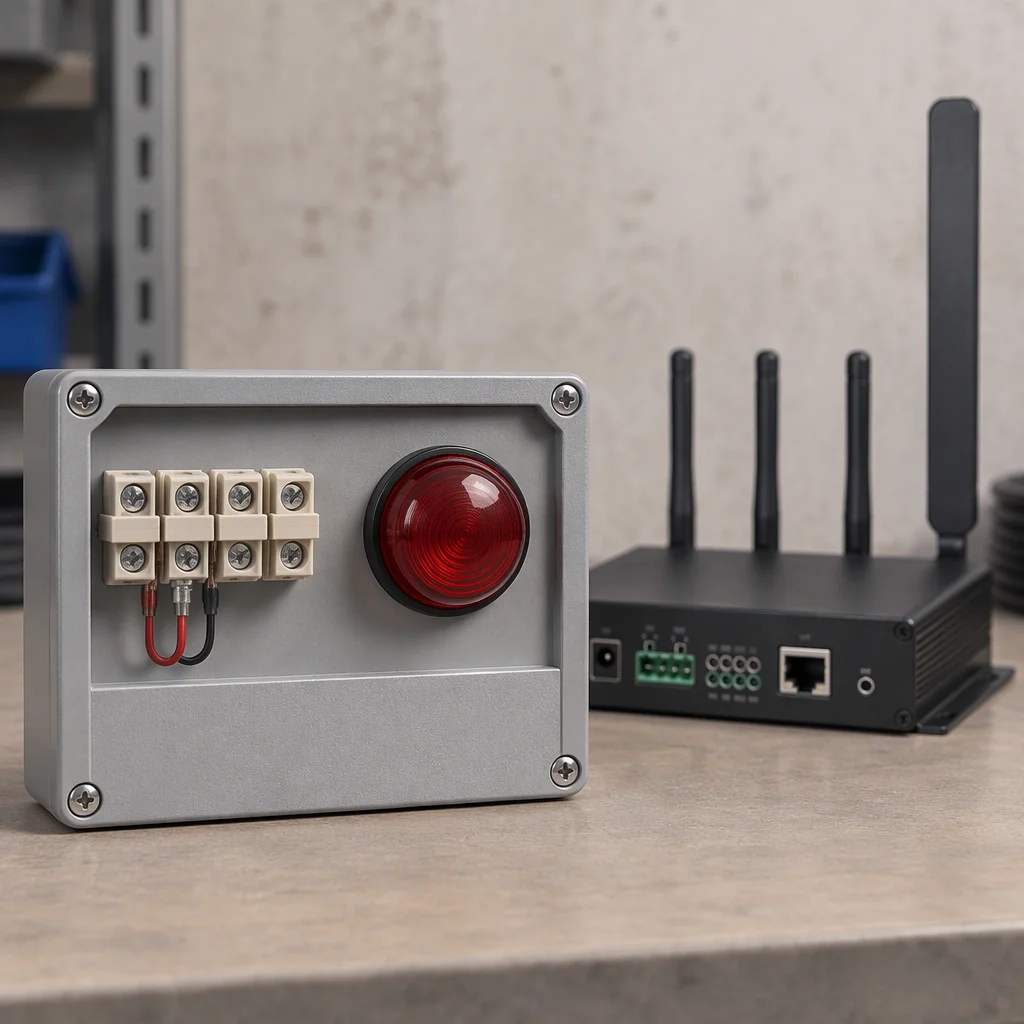
Dry contact: it carries the alarm, and it carries nothing else.
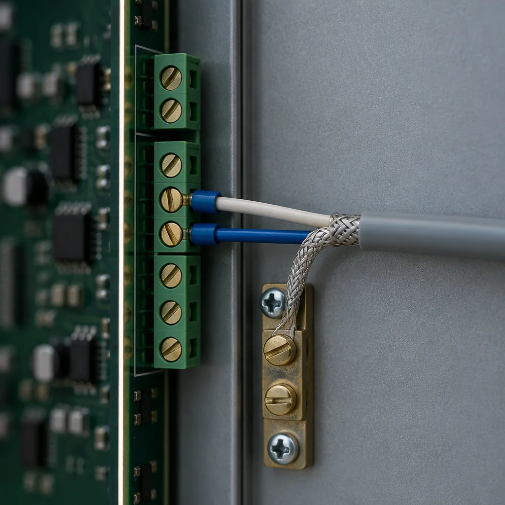
4–20 mA: one loop per reading, into whatever takes a current input.
Read next · Controllers · Design guides · FAQ
A reading is only an alarm once there is a baseline
A site that installs the instruments and writes down nothing has five numbers and no way to read them. The reading on the panel is not evidence on its own; the evidence is the same reading on the same day last month, taken the same way. That record is what turns a number into a decision.
The baseline is cheapest to take during commissioning, while the loop is open and somebody is already at the panel. After that it is a schedule: one pass a month through the same list, entered in the same columns, so a drift shows as a slope rather than as a surprise.
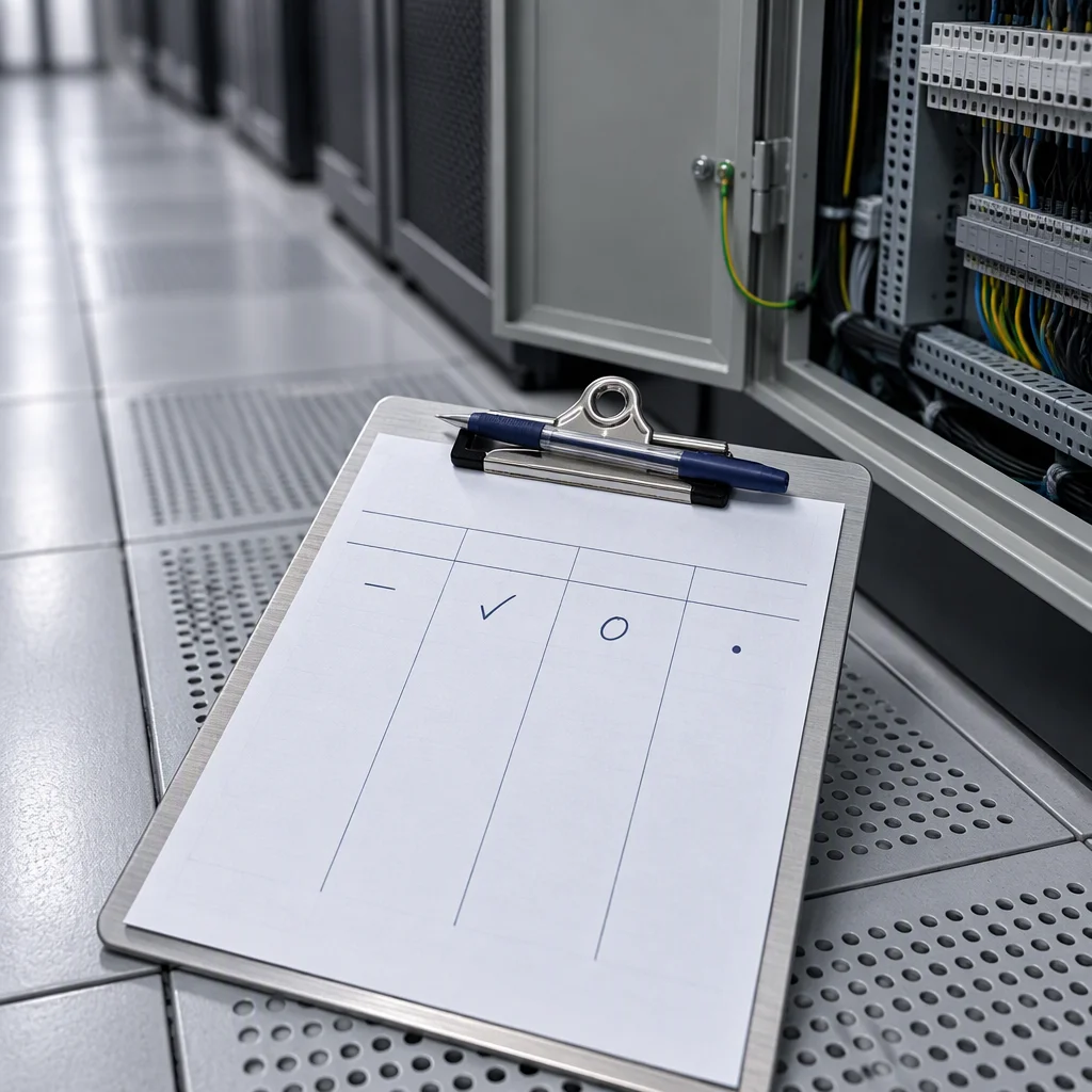
The first entry is the one every later entry is compared against.
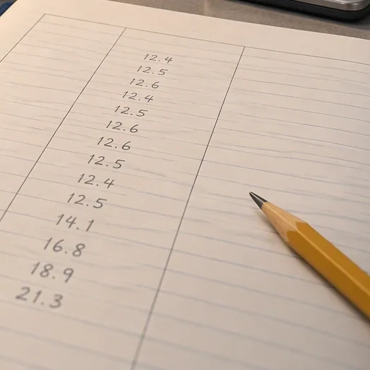
A slope is readable. A single number on a screen is not.
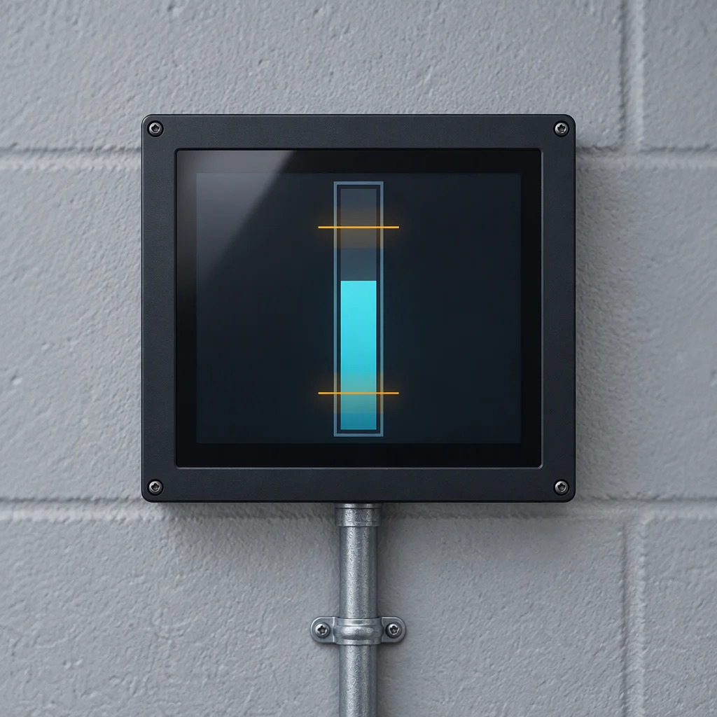
The band is set on what this loop does, not on what the datasheet allows.
The baseline is a record of this loop. It does not transfer from another site, another fill, or another coolant batch.
Read next · Commissioning · Notes on ISO 4406 · Projects
Four documents are held for this sheet. Tick the ones you need.
Tick a document, name the loop and the readings you are fitting, and the file comes back attached.
One business day, with the file attached.
Nothing else on this sheet is promised. Price, stock and lead time are not promised here.
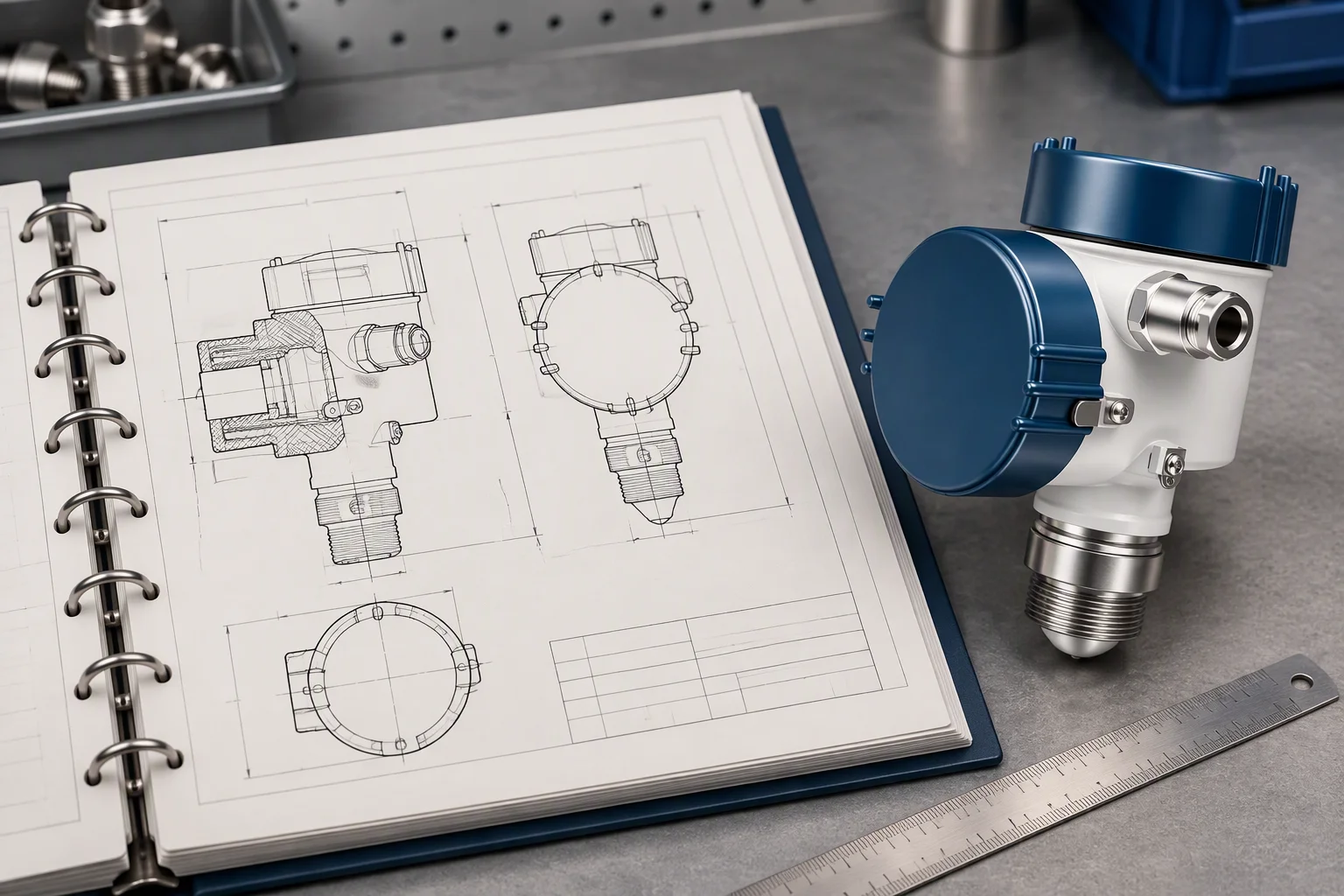
The file is held per line, at its current revision.
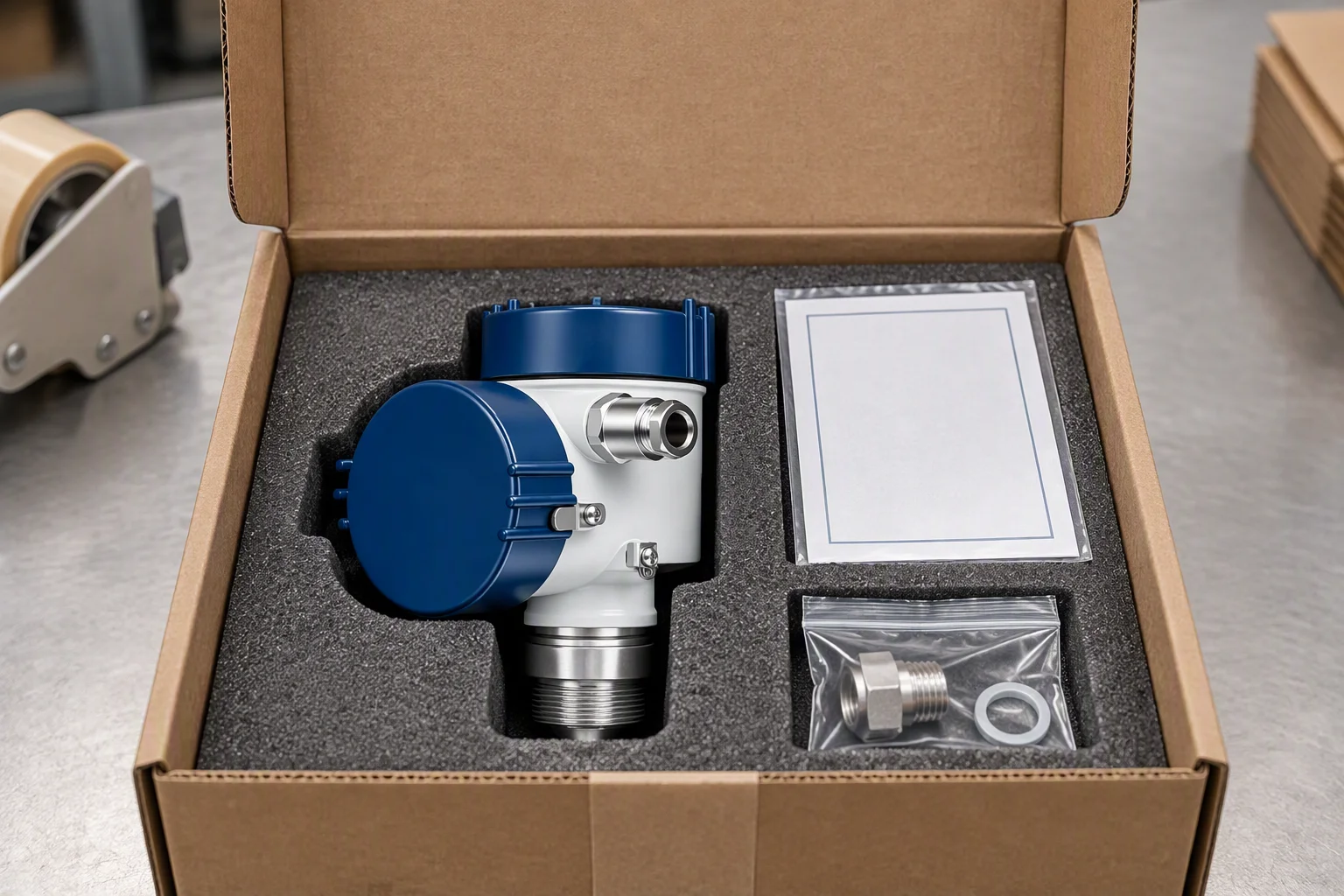
Certificate and drawing travel in the carton, not in a later email.
