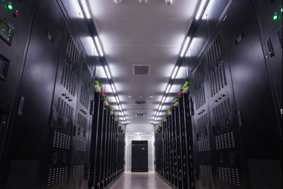
Six industries, six different failures
One loop, six ways of failing it. Each sheet below states what that industry is quoted on and what the same hardware has to be built to, in the same order every time: the pain, the conditions, the loop, the standards, the configuration files.
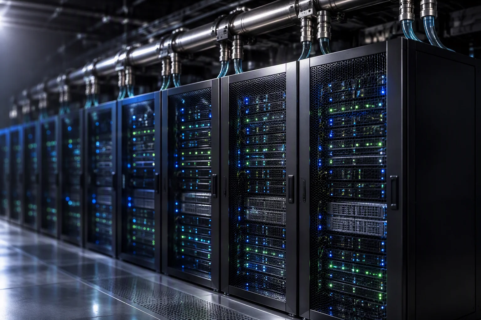
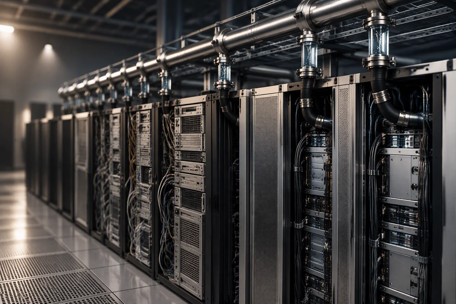
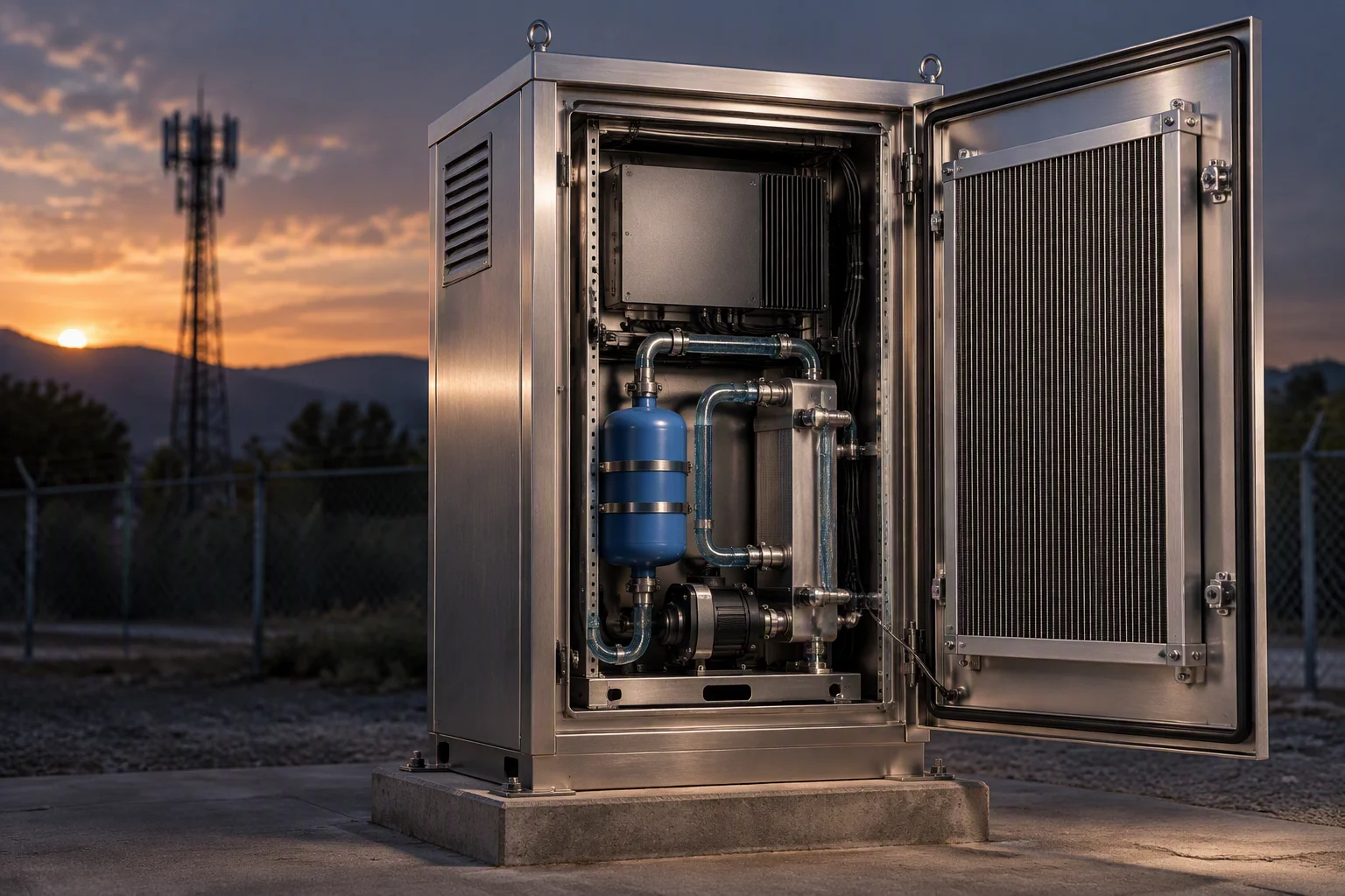
One business day, with the file attached
Six industries, six different failures
A row links to the sheet that argues it. The figures are the ones that sheet is written against, not a summary of them.
What that failure looks like in a hall
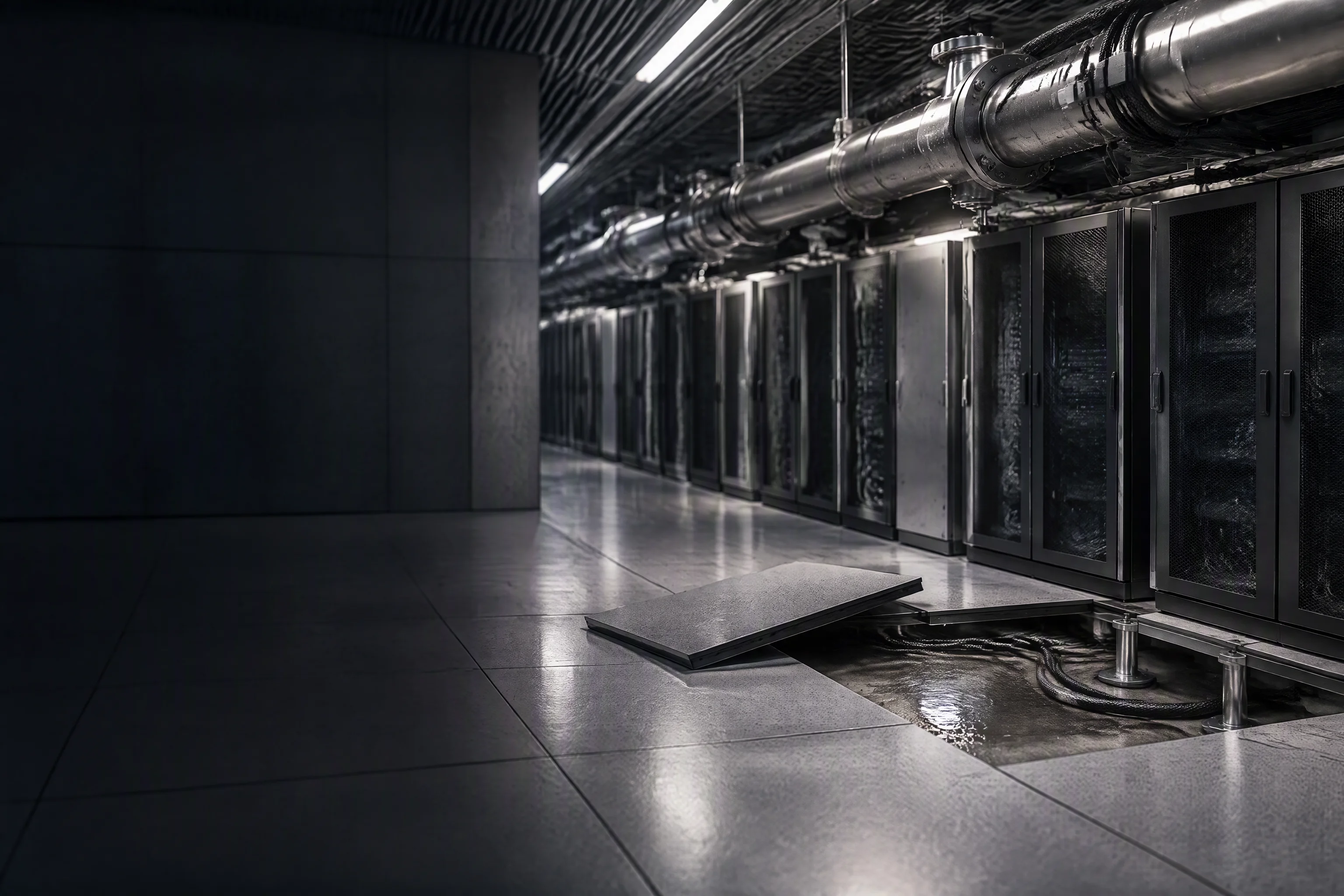
Under the floor is where a leak is found, while the round walks on top of it
0.1 m the position a locating rope reports along the run
30 s from water on the rope to an alarm at the controller
Every industry on this sheet loses the same thing first: the time between the fluid arriving and anyone knowing.
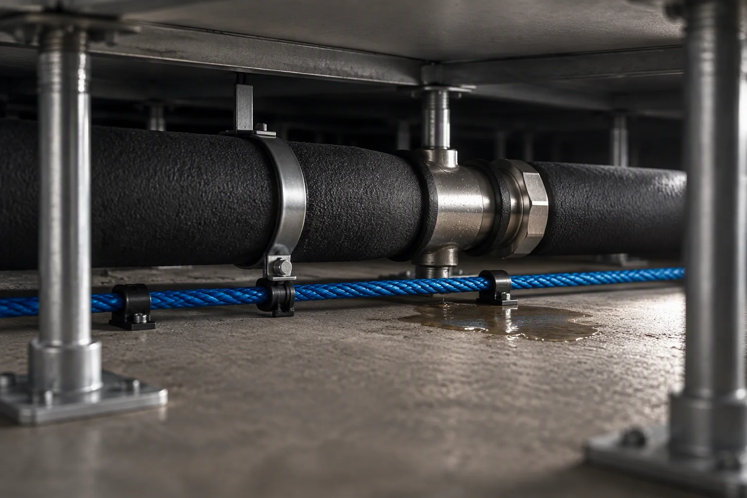
The cable is laid where the fluid would arrive. The inspection route is upstairs.
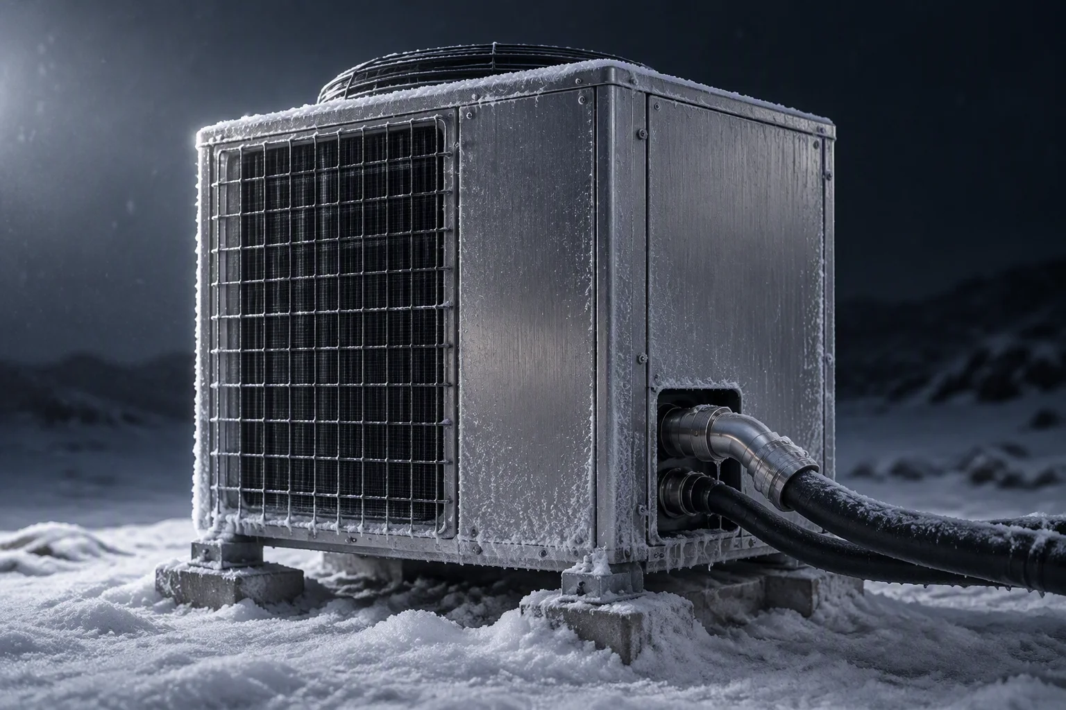
At an unattended site the first failure and the first reading can be weeks apart.
The conditions all six are quoted on
| No | Condition | Value | Unit | Basis |
|---|---|---|---|---|
| 01 | Leak location resolutionLocating sensing rope | 0.1 | m | On 500 m of rope per channel, alarm inside 30 s |
| 02 | Detection length per channelLocating sensing rope | 500 | m | Longer runs split across two channels rather than one |
| 03 | Alarm responseController to BMS | 30 | s | Includes the locating calculation, not just contact closure |
| 04 | Cartridge absolute ratingFilter grade in circuit | 1 | µm | Grades from 0.05 to 100 µm on one housing |
| 05 | Cleanliness at chargeLoop fluid | 17/15/12 | ISO 4406 | Sampled and gated before the loop is charged |
| 06 | Filter change differentialAcross the housing | 0.5–0.7 | bar | With a transmitter on two impulse tubes |
| 07 | Shell design pressure304 and 316L | 1.0 | MPa | Hydrostatic proof per batch |
| 08 | Hose working pressureDASH −4 to −10 | 1.38 | MPa | About 200 psi, burst above 5.5 MPa |
| 09 | Hose temperature bandWater-based coolant | −40 to +99 | °C | The band claimed for this application |
| 10 | Flame rating on the coverHose outer layer | V-0 | UL 94 | Outer cover compound only, not the liner |
The value column is the figure we will be held to, and every figure in it is one this loop is bought against. Where a tolerance is not published, the cell stays empty rather than carrying an estimate.
Where those figures are produced
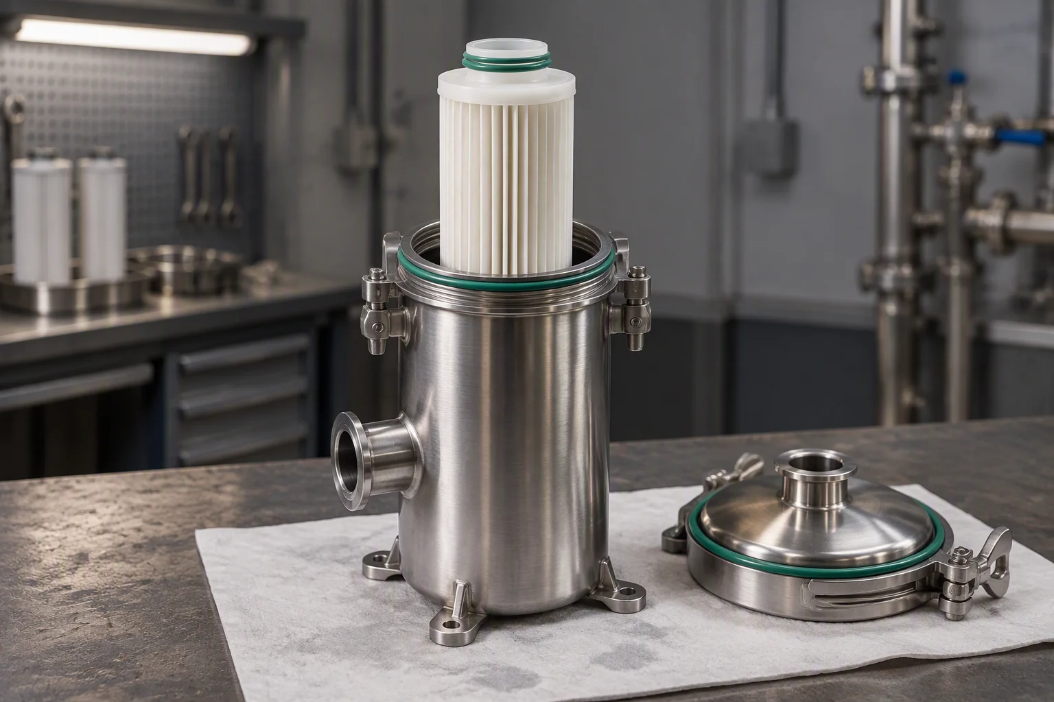
One cartridge rating has to hold across all six industries: 1 µm absolute, from 0.05 to 100 µm.
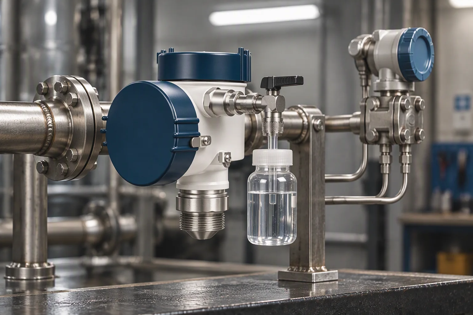
Cleanliness at charge is a sample, not a claim: ISO 4406 17/15/12 before any fluid goes in.
The loop all six of them consume
Consumables on this section
- 1 ·Boundary of this sheet: the CDU is not supplied
- 2 ·Row manifold, with a dry-break coupling pair per rack
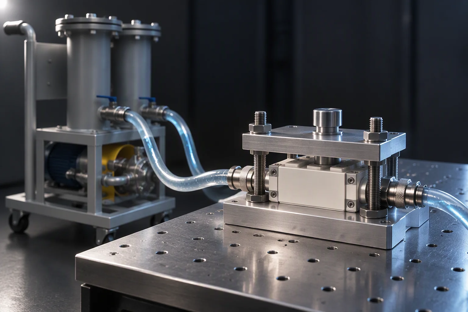
- 3 ·Rack drop hose, EPDM, 1.38 MPa working
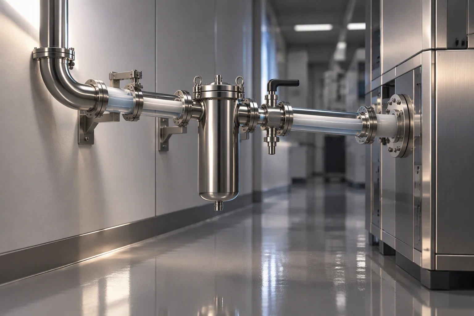
- 4 ·Filter on the return leg, 1 µm absolute
- 5 ·Differential pressure transmitter, 0.5–0.7 bar band
- 6 ·Locating sensing rope, under the tray and under the floor
The positions on that section that wear
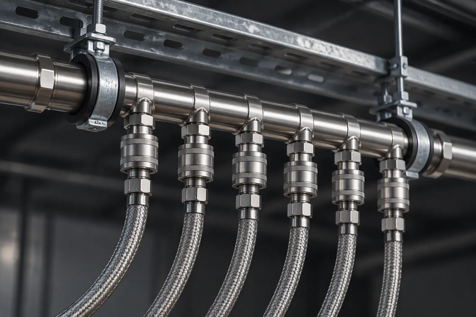
Every rack takes its own pair, so the joint count follows the rack count.
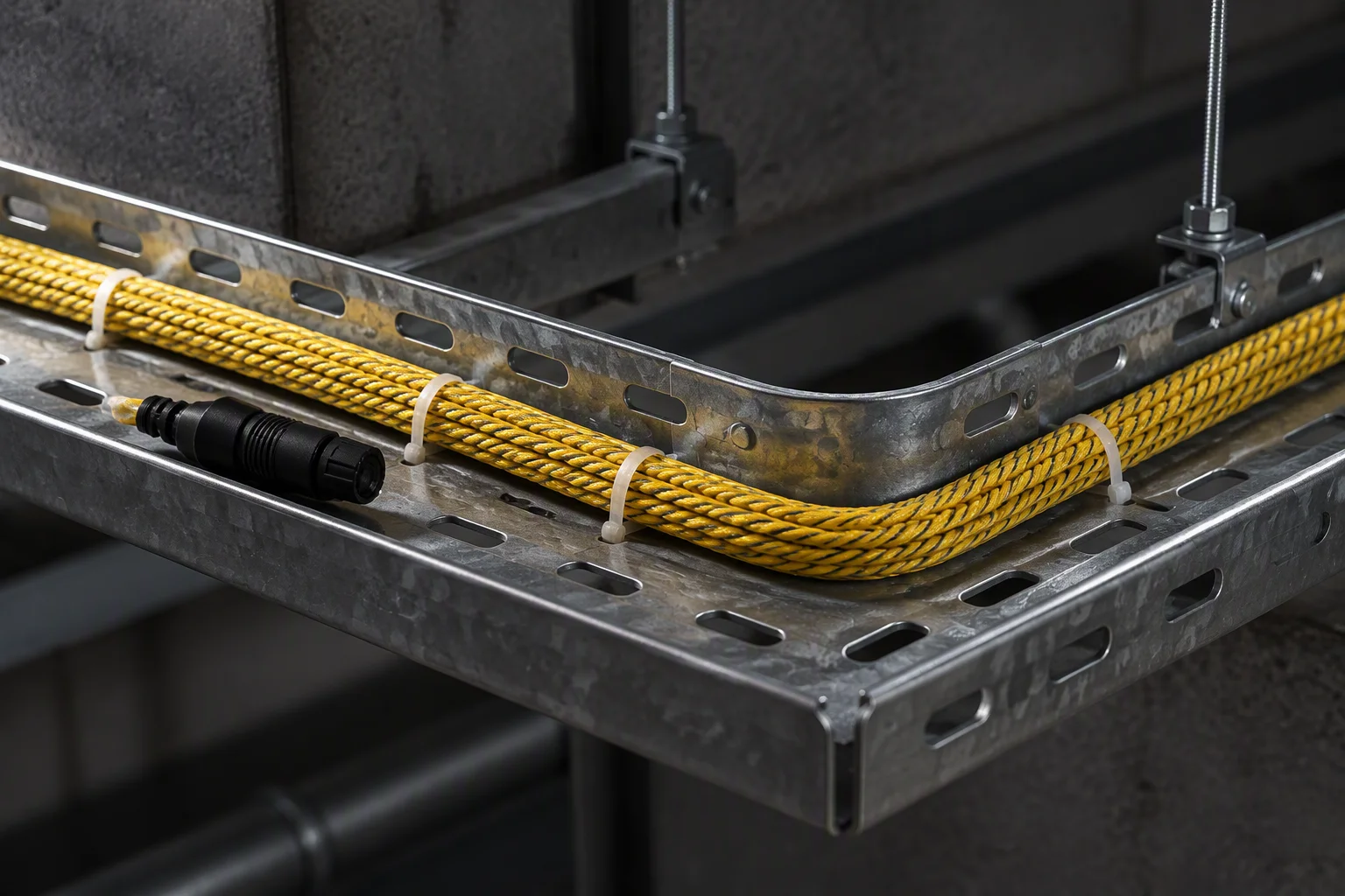
The rope goes where the fluid would go, not where the round walks.
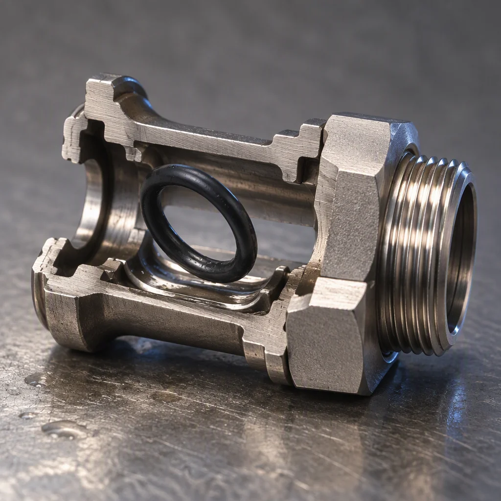
The failure every one of the six reports is at the face, not at the heat exchanger.
The standards family these six sheets are written against
How those standards are demonstrated
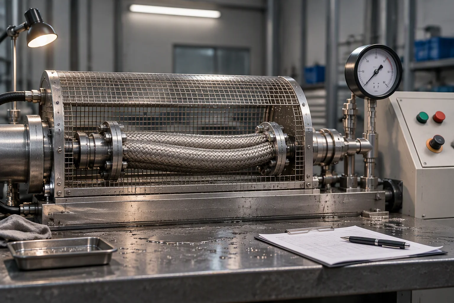
Hose is held to 1.38 MPa working and burst above 5.5 MPa before a batch leaves.
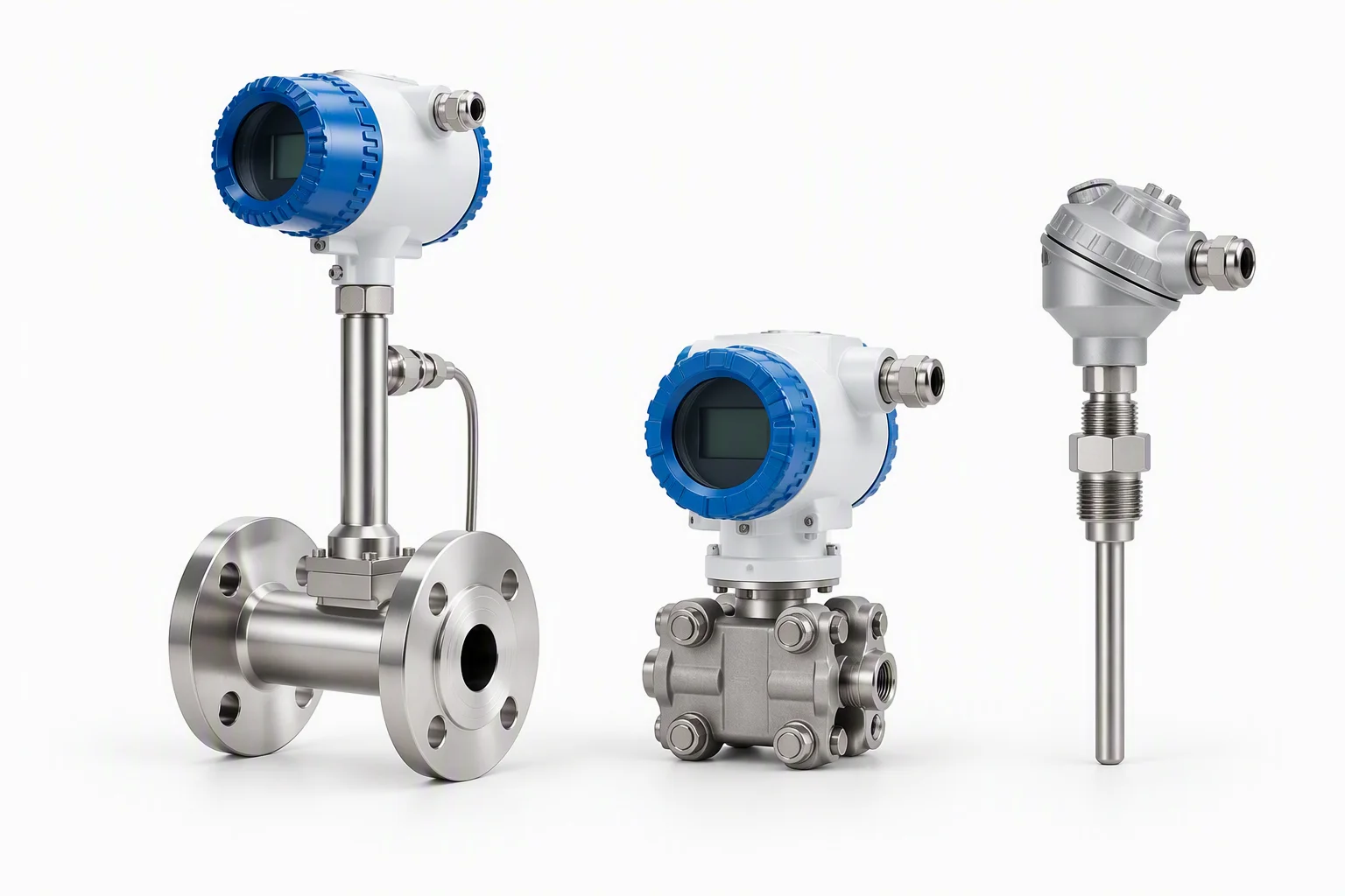
Five quantities on the loop: flow, pressure drop, conductivity, pH and level.
What stops at the boundary of this sheet
We supply the loop: hose, couplings, seals, filtration, sensing rope and the instruments that read them. The cooling distribution unit and the cold plate are not ours to quote, and neither is the installation, the design or the commissioning of either.
Both boundaries are stated on every sheet in this set, because a supplier who will quote anything is a supplier whose schedule cannot be checked.
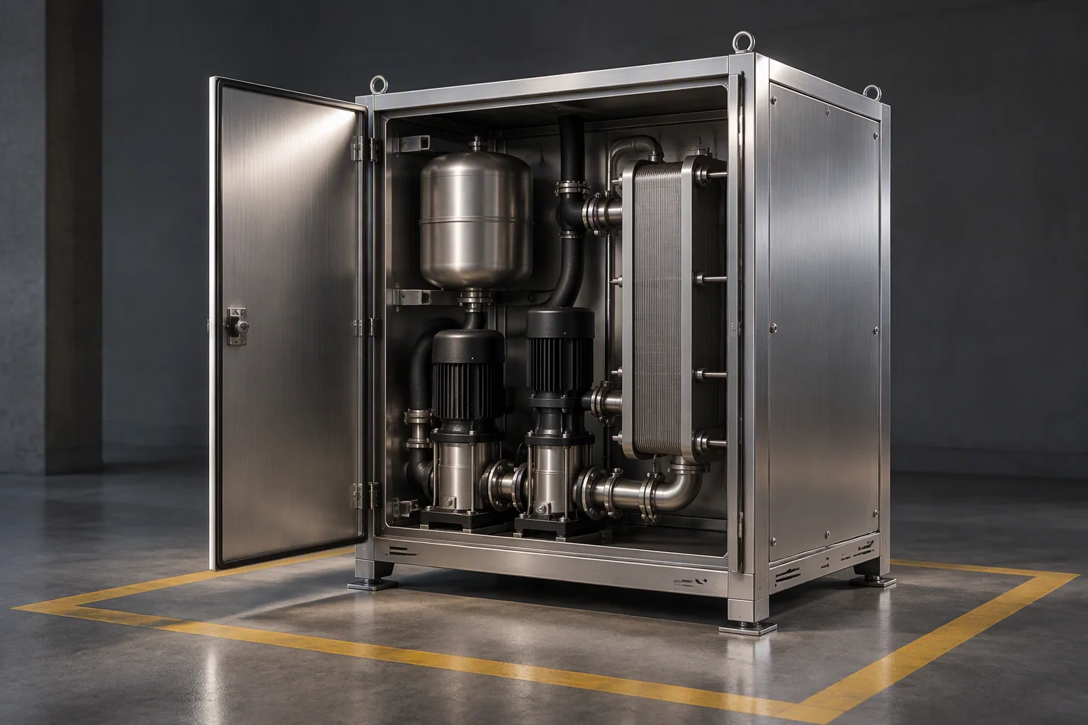
The boundary is drawn at the CDU, not for lack of interest but so this schedule stays checkable.
Configuration files, not case studies
Three loop shapes cover most of the work these six sheets are indexed on. Each is held as a file: the loop drawing, the consumable list, the cleanliness gate and the sample that cleared it.
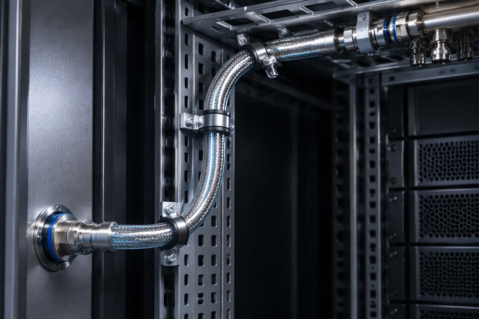
File A. Couplings at the cabinet, isolation at the rack.
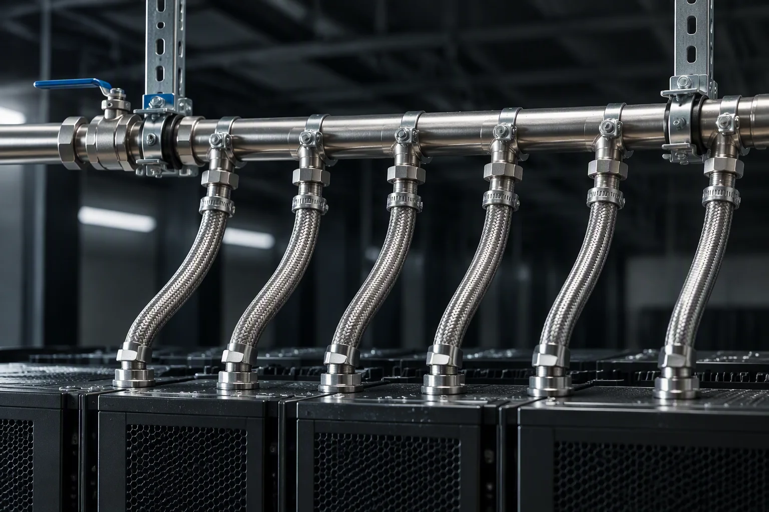
File B. One manifold per row, isolation at the head of the row.
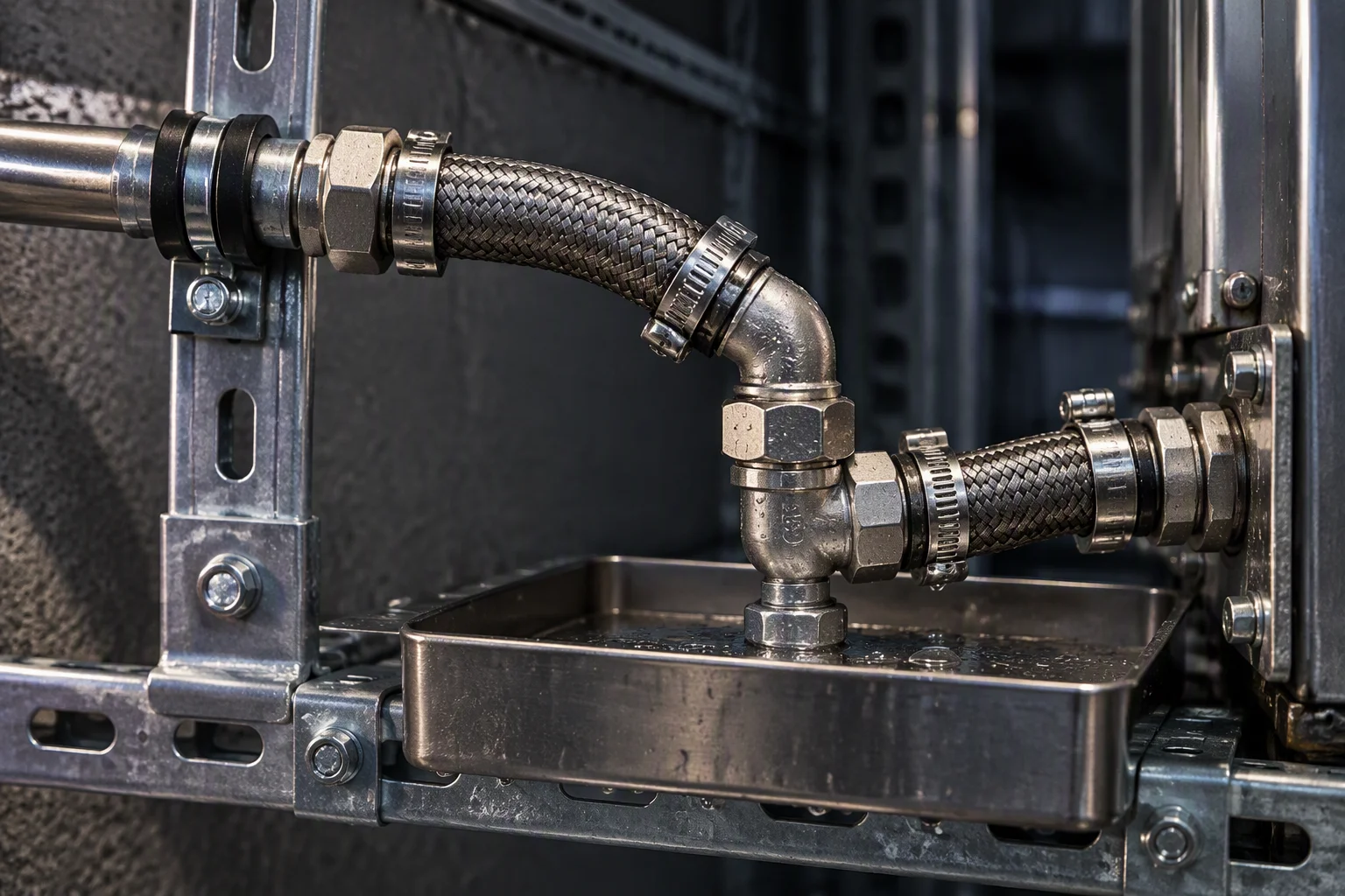
File C. The last branch to the accelerated trays: shortest run, most joints.
The parts behind every one of those files
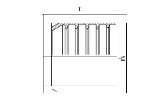
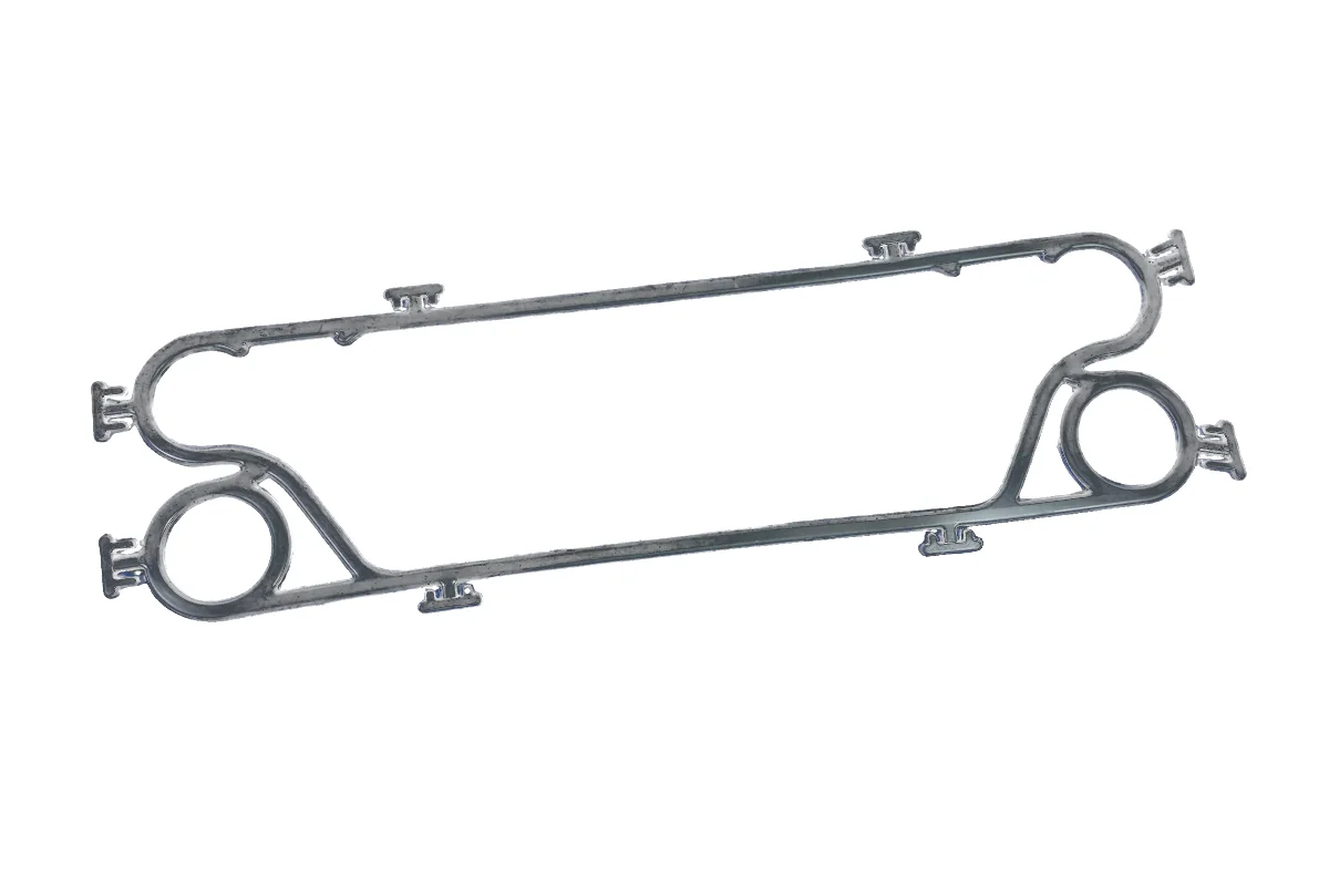
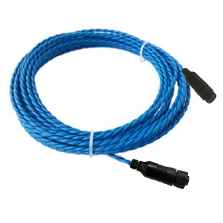
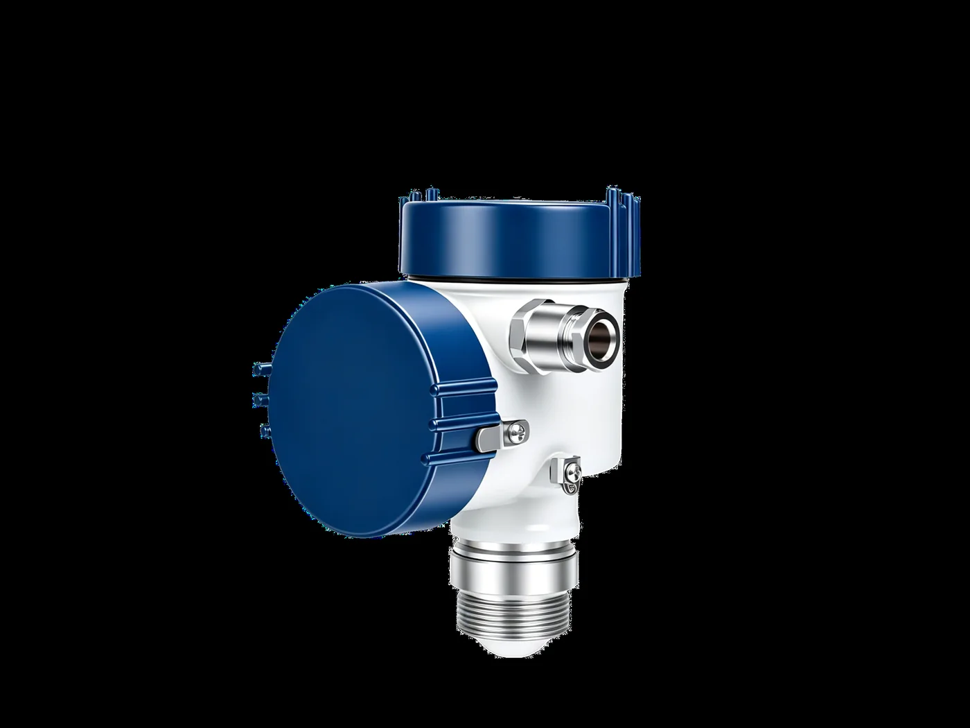
SP 1–4 ·Supply-side samples held against Schedule A: a coupling section with its seal groove called out, a moulded profile gasket, locating rope at 0.1 m resolution on 500 m per channel, and the transmitter that reads the filter differential.
Four documents are held for this set. Tick the ones you need.
Tick a document, name the industry you are planning against, and the file comes back attached.
One business day, with the file attached.
Nothing else on this sheet is a commitment. Price, stock and lead time are not promised here.