EMS-Trade
Cooling
Loop consumables

Document ECT-01 · REV C · ISSUED 2026-09 Six lines · 48 sheets

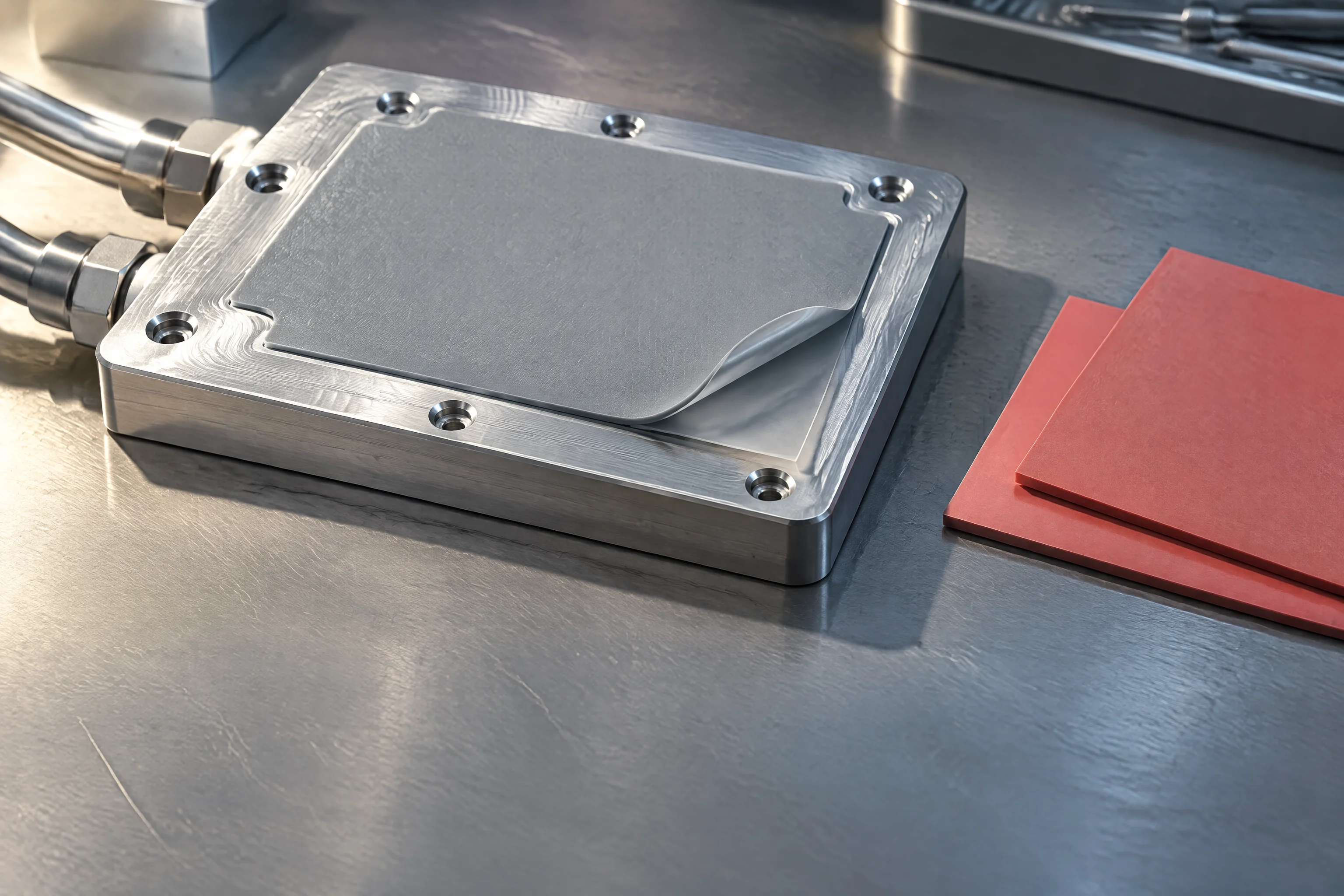
A cut gap filler pad laid onto the machined face of a cold plate on a bench, the pad outline following the die footprint, with a second pad of a different thickness beside it
Plate 01 · Gap filler pads · thermal materials

Gap filler pads for the liquid cooling loop

A pad closes a gap grease cannot. It takes the tolerance stack, and it hands back an interface on each face.

Request the specification file One business day, with the file attached

Interface range 1.2–7.5 W/m·KLoop envelope −40 ~ +99 °CCleanliness ISO 4406 17/15/12

01

The order a pad is judged in

Section 01 · the selection schedule

The schedule below is ordered by the trade a buyer actually makes, not by how many parameters can be listed. Interface conductivity first, because that is the figure a quotation carries.

Thickness second, because thickness is what closes the gap. Then the two conditions that decide whether either figure still means anything in the second year.

Gap filler pads · the order the trade is made in
Order Parameter Why it comes here What you accept with it
01 Interface conductivity 1.2–7.5 W/m·K The figure the quotation carries, and the easiest one to compare
02 Thickness ordered per joint Closes the gap; the number on the purchase order
03 Compression set by the joint Not a free property: the pad gives as far as the joint closes
04 Receiving face flatness controlled A machined face with tool marks is bridged, not mated
05 Cut and outline to the drawing Cut before packing, so nothing is trimmed on site

Compression is the row buyers skip. The same pad at a different joint closure is a different interface, and the quotation cannot say which one you bought.
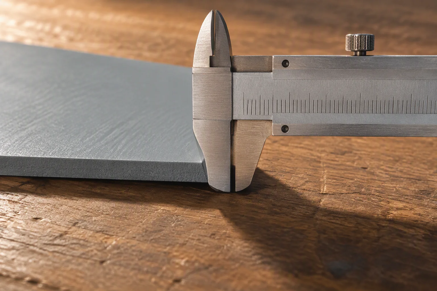
A vernier caliper closing on the cut edge of a grey thermally conductive pad lying on a bench, the jaw flat against the sheet
PL 01

Measured at the cut edge, on the sheet, before it is packed.
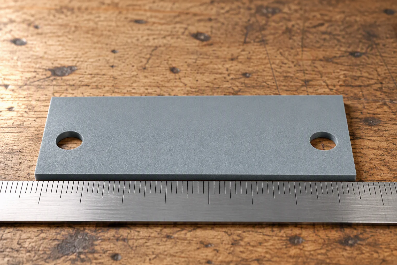
A die-cut pad with a rectangular outline and clearance holes for two fasteners, laid flat on a steel rule on a workbench
PL 02

Die-cut to the outline, with the fastener clearances already in it.

Read next · Grease and phase change · Thermal materials

02

The grades, photographed side by side

Section 02 · the difference a grade makes

A grade is not a colour and not a thickness. It is the filler loading in the compound, and it shows at the cut edge: a soft grade deforms against the blade, a hard one cuts clean. Both are on this sheet at the same size.

Soft grades tolerate a rough receiving face. Hard grades need the face controlled and give more back per degree.

Three thermally conductive pads of different thicknesses standing on their cut edges in a row on a bench, the sheet thickness readable as a band across each
PL 03

Three thicknesses from one grade, stood on their cut edges.
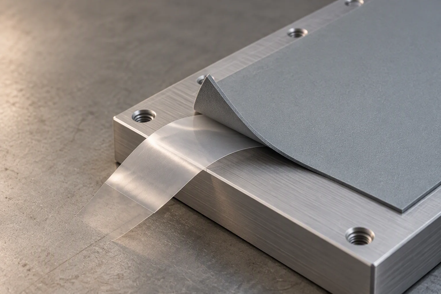
A pad being laid onto a cold plate face, one corner still lifted between two fingers of a gloved hand, the release liner peeled back underneath
PL 04

Laid in one movement, liner peeled from under it as it goes down.
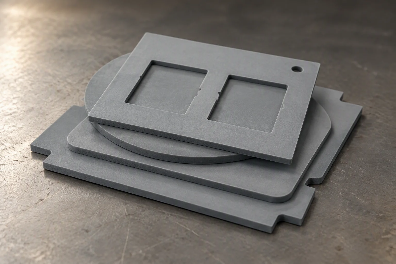
A stack of die-cut pads on a bench, each outline different, the top pad showing a narrow bridge left between two cut-outs
PL 05

One order, several outlines: the cut follows the parts, not the sheet.
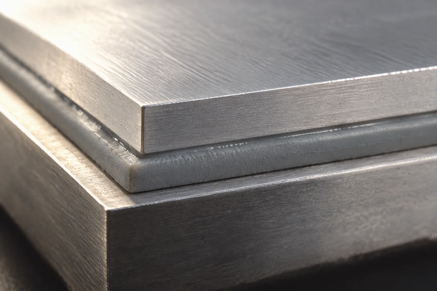
A pad pressed onto a heat spreader under a flat plate, the cut edge slightly proud of the spreader outline on every side
PL 06

Proud on every side: a pad cut short of the footprint is a pad that is not covering it.
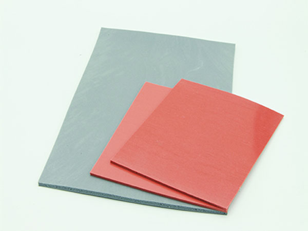
Two gap filler pads on a white ground, one large grey pad and one smaller pink pad, both with a clean straight cut edge
PL 07 Two grades as supplied 1.2–7.5 W/m·K The pink grade is the softer of the two and the one that tolerates a rougher face.
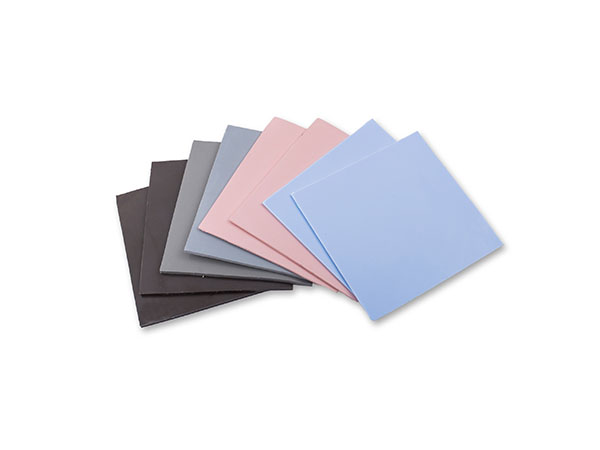
Thermally conductive pads fanned on a white ground in black, dark grey, light grey, pink and blue, each a different compound
PL 08 Colour is a compound code five compounds shown Colour separates compounds on a bench. It is not a grade and not a thickness, and it is not ordered by colour.
03

The envelope the pad has to live in

Section 03 · boundary conditions of the loop

Interface range
1.2–7.5 W/m·K for the class as supplied
Loop temperature
−40 ~ +99 °C at the joint on the data hall side
Coolant pressure
1.38 MPa ≈ 200 psi working pressure at the manifold
Cleanliness
ISO 4406 17/15/12 before first power-up, so the face is clean when the pad lands
Flammability
UL 94 V-0 on the polymer parts inside the hall

Past the envelope the pad is not a degraded interface, it is a wrong one. A joint that runs hotter or wetter than this is outside the class, and no grade of pad brings it back inside.
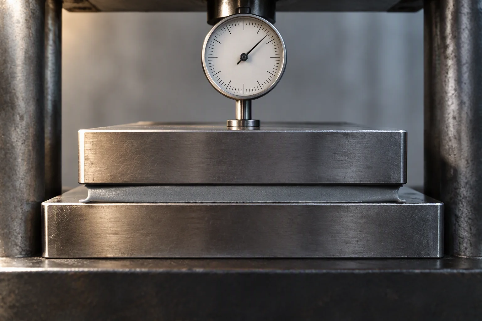
A pad between two steel platens in a compression frame, a dial indicator on the upper platen showing how far the joint has closed
PL 09

Compression measured as closure, not as a property of the sheet.
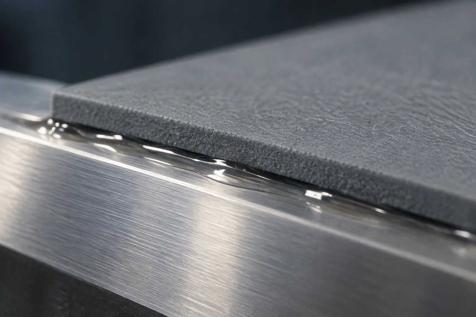
A joint area after a wet test: a pad edge seated against a machined face with a run of coolant along the seal line beside it
PL 10

The pad sits behind the seal, never in it. Its job is conduction, not containment.

04

How a pad is used wrong

Section 04 · the four common ones

  1. 01 Pad cut short of the footprint The uncovered strip is still an air gap. The measured interface is the pad's, carried by the part of the joint that has one.
  2. 02 Thickness chosen off the sheet A pad thicker than the gap holds the joint open; a thinner one leaves the air back in. Both read as the right grade on the quotation.
  3. 03 Fasteners torqued over the pad A pad does not set a joint height, and it will not hold one. The closure is set by the metal, and the pad fills what is left.
  4. 04 Pads stored in the open A pad picks up dust and swarf on the bench. With the loop held to ISO 4406 17/15/12, the face it lands on is cleaner than the bench it was laid on.
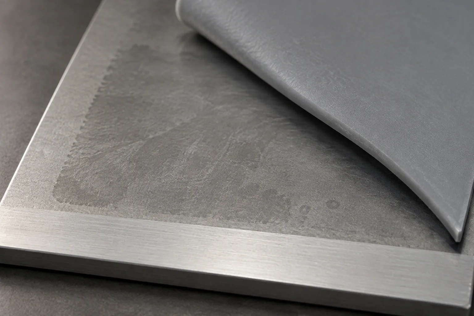
A cold plate lifted off a module with the pad still stuck to the plate: the pad imprint covers part of the die footprint and stops short of one edge
PL 11

The imprint is the record of the joint: what the pad covered, and what it did not.

05

Documents and packing travel with the order
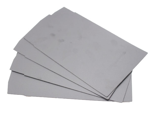
Section 05 · what is on the purchase order

Specification sheet Grade, interface range, thickness and the outline the pads are cut to. Per order
Material certificates EN 10204 3.1 on the metal parts that travel with the same shipment. On request
Thermal report Interface performance of the grade supplied, before and after cycling. On request
CE marking, RoHS and REACH Compliance statements for the imported goods, issued with the shipment. ISO 9001 covers the supplied lot. With the goods
A counted stack of light grey thermally conductive pads of one thickness, corner-aligned on a white ground
PL 12 Counted in the stack one thickness per line A pad order is a count and a thickness. Both are restated on the packing list.
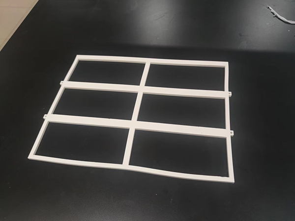
A moulded silicone frame of six white rectangular cells, flat on a dark worktop, with an even wall around every cell
PL 13 Moulded frame holds the interface Where a joint is opened for service, a moulded frame keeps the interface where the drawing put it.
DOCUMENT REQUEST

Request the specification file

Four documents are held for this line. Tick what you need and one reply returns them, attached, on the next business day.

  • Specification sheet grades, thicknesses and cut outlines
  • EN 10204 3.1 material certificates metal parts
  • Thermal report before and after cycling
  • Outline drawings die-cut pads
The only promise on this page

One business day, with the file attached.

No other commitment is made on this sheet. Price, stock and lead time are not promised here.

If the form cannot send, this address takes the request instead: sales@ems-cool.com
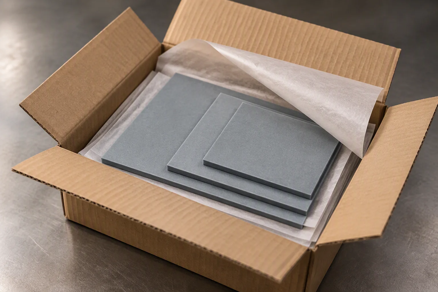
Cut pads of several outlines laid flat between two sheets of release paper inside an open carton on a bench
PL 14

Packed between release paper, outlines kept flat and separated.
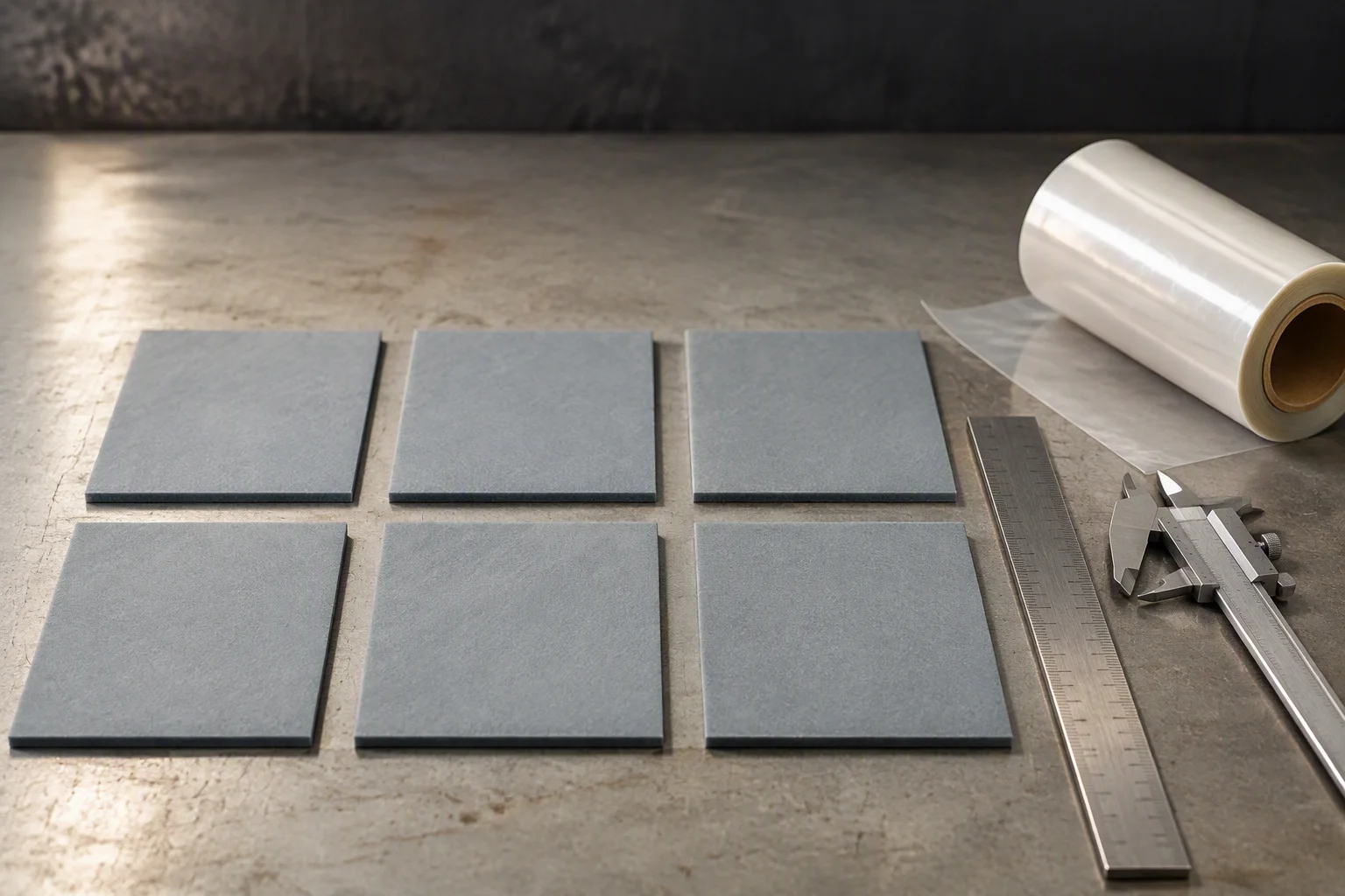
A bench prepared for a pad order: cut pads laid out in outline order, a steel rule, a caliper and a roll of release film beside them
PL 15

The file follows the bench: grade, thickness and outline, one line per part.