
Locating sensing rope
One channel of rope reports a position along the run, not a zone. The controller times the change in impedance between two braided electrodes and returns the distance to the wet point.
One business day, with the file attached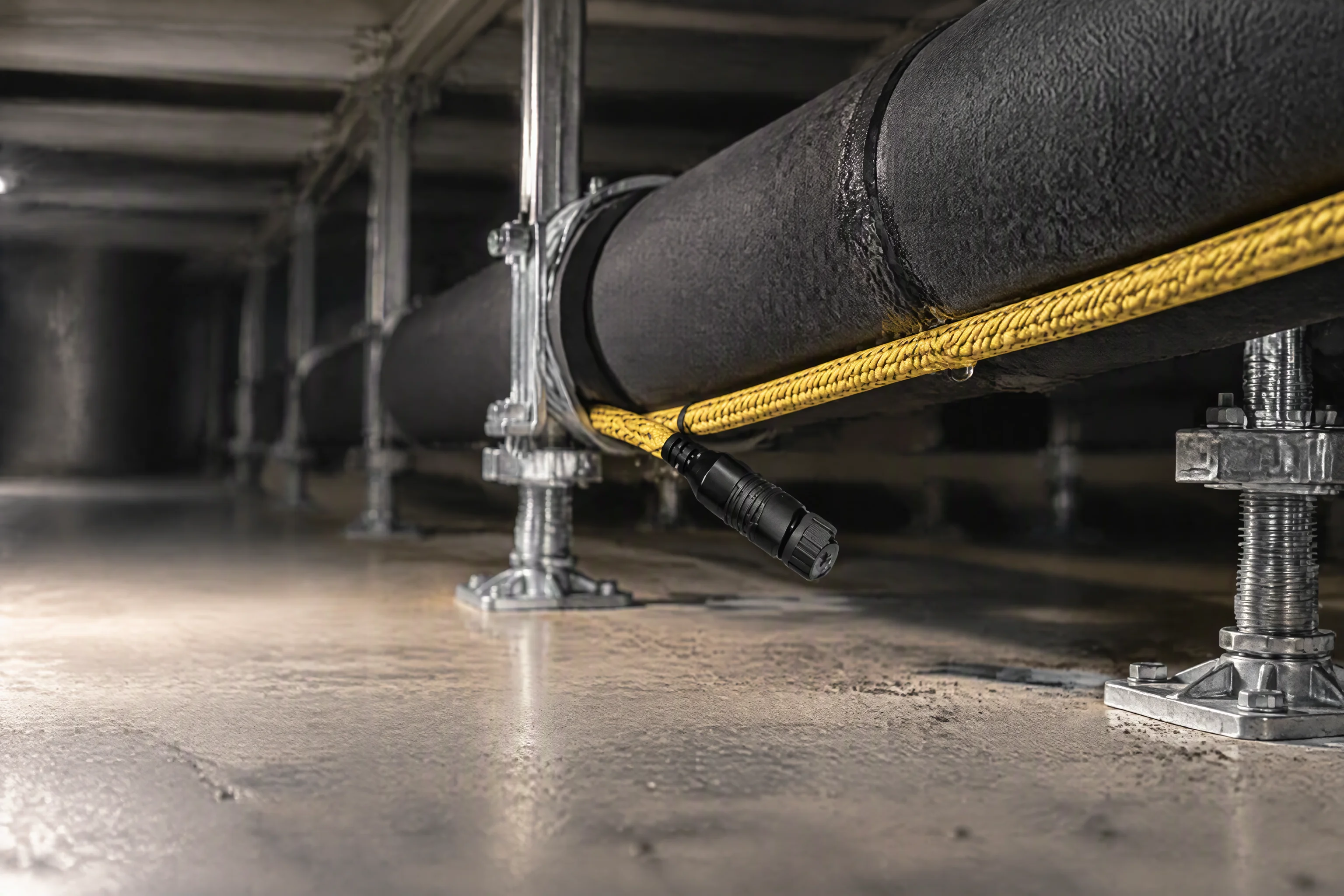
Rope is laid where the coolant arrives, not where the round walks. On the slab, beside the pipe.
Choose the run first, the rope second
A rope is chosen by the run it has to cover, not by the diameter of the cable. The rows below are in the order a loop is actually specified: how far one channel reaches, what has to come back from it, and what the air around it is like.
Rope is cut to the run and terminated at both ends before it leaves the reel. A site that cuts and re-terminates on the slab changes the length the controller was calibrated to, and every position reported afterwards reads short by what was removed.
| Criterion | What you decide | Figure | If it is specified wrong |
|---|---|---|---|
| Length of the run | One channel of rope, or the run split across two | 500 m per channel | Past that the far end falls outside the locating calculation |
| What has to come back | A position along the run, or only the area | 0.1 m | A zone sends the technician to the wrong aisle |
| Air around the rope | Woven jacket, or plain twisted pair | dust weave | Dust, condensation and metal particles alarm a dry run |
| A gland between runs | Rope with an in-line module, or two plain runs | 1 addressable place | Two channels spent on one drop |
| How many areas | One controller, or a second one later | 4 · 8 · 16 | A shared channel names a wet tile, not which aisle |
| What the BMS speaks | Modbus RTU, a volt-free relay, or an analogue loop | 4–20 mA | A protocol converter added after commissioning |
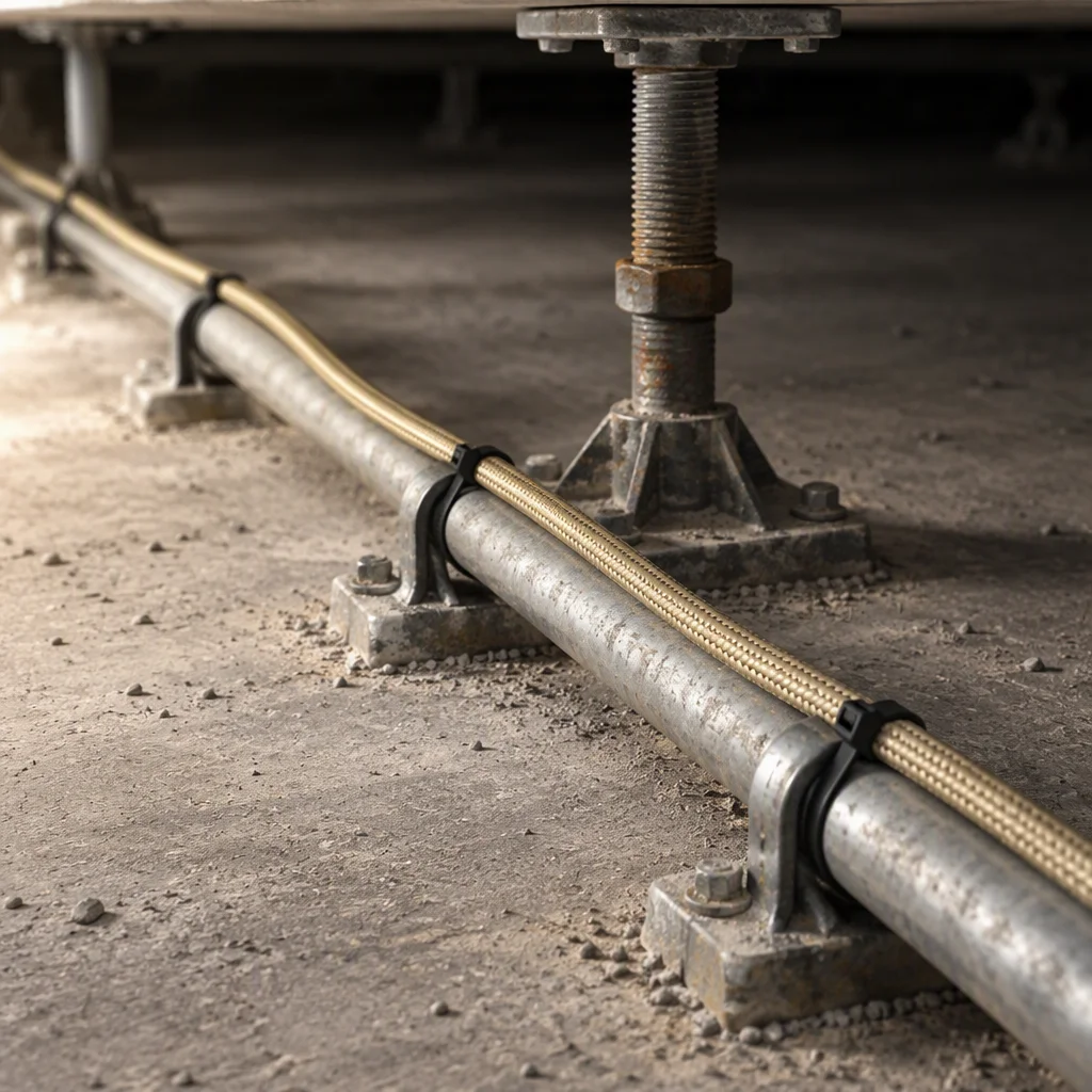
The run is the unit of selection. One channel, one route, up to 500 m.
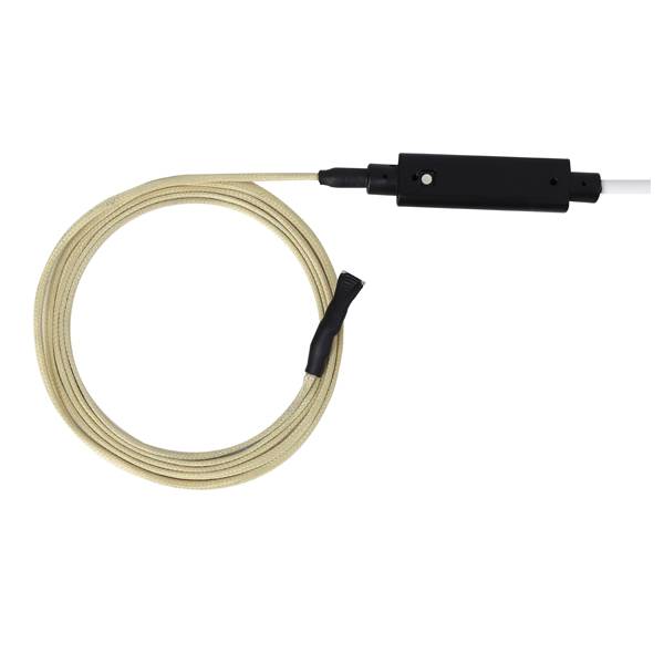
A rope set with its module, cut and terminated before it is packed.
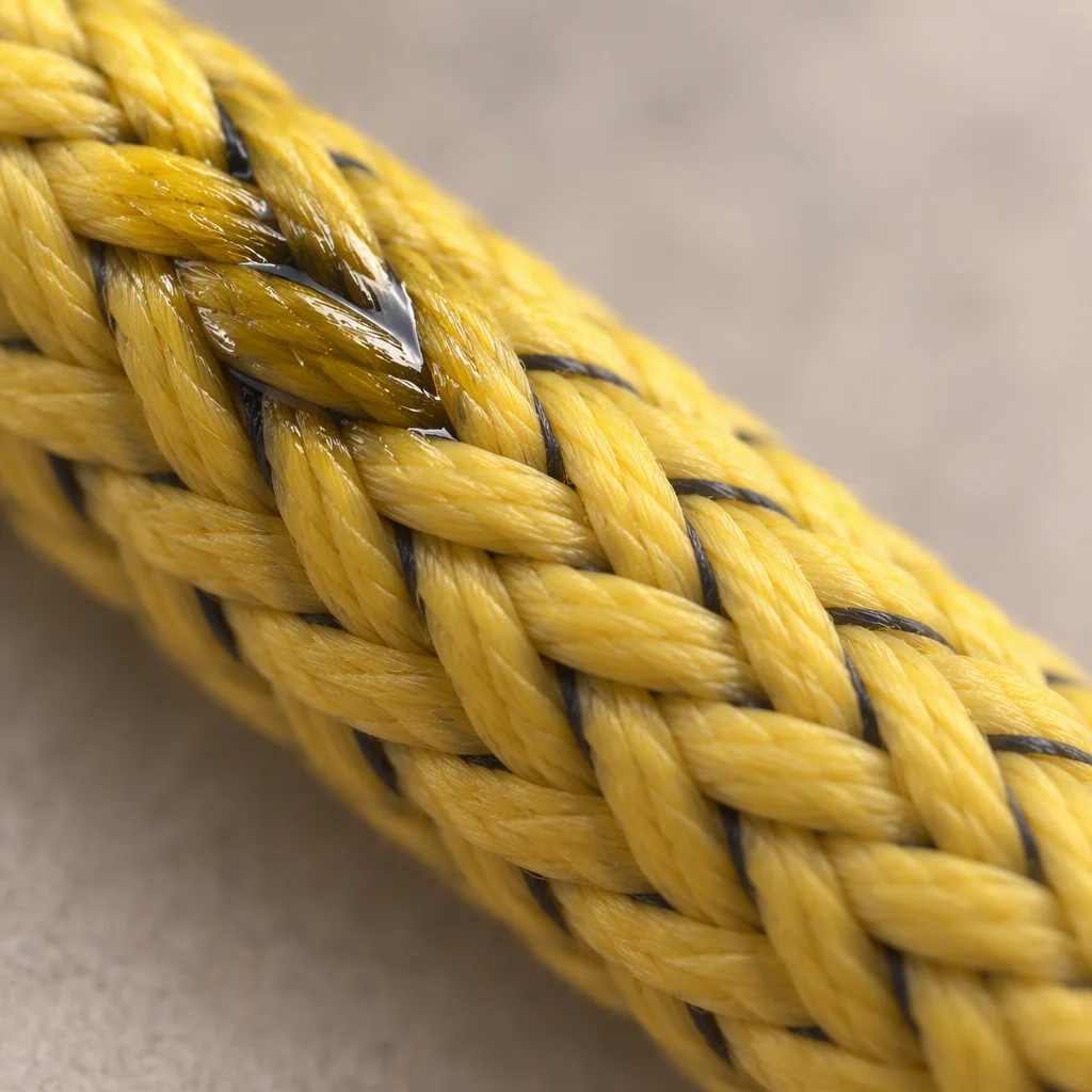
Water between the two electrodes is the measurement.
Read next · Point sensors · Controllers
Three rope constructions, and what each one buys
Three constructions cover the range. What separates them is visible in the jacket and in what sits between the electrodes, and each one answers a different condition in the void.
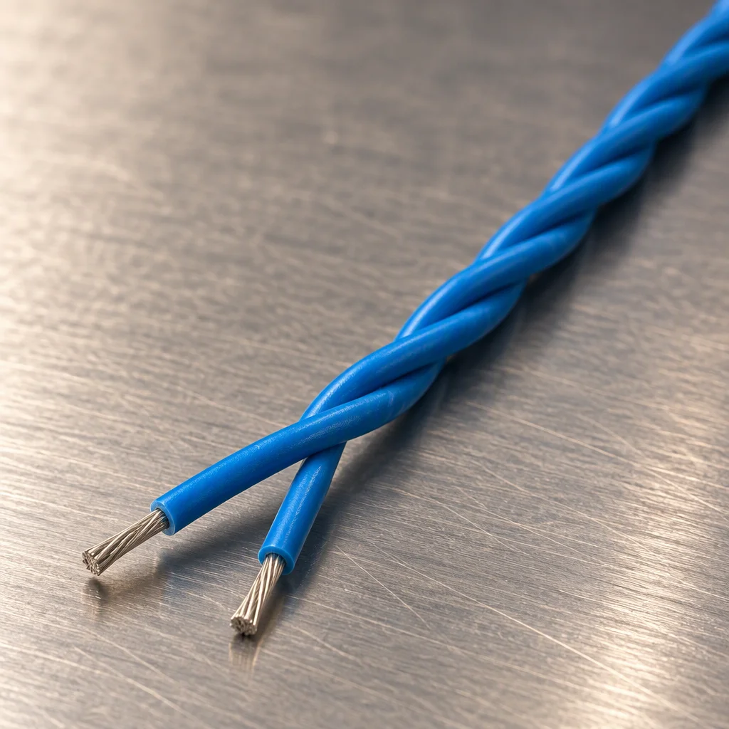
Twisted pair: the two electrodes are the pair, with nothing over them.
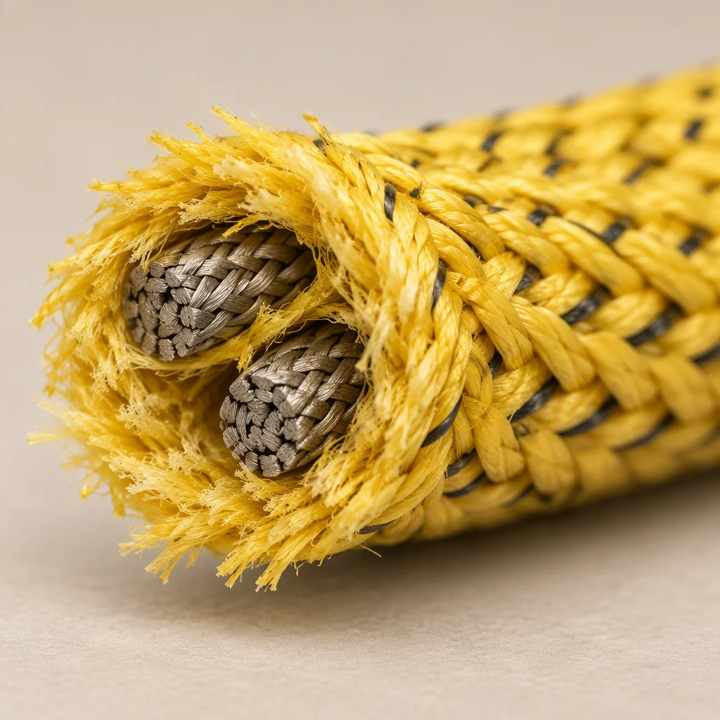
Woven jacket: the dust weave over two braided electrodes.
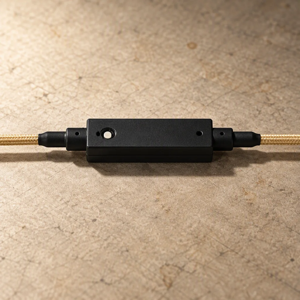
Module: the same rope, one place on it addressable on its own.
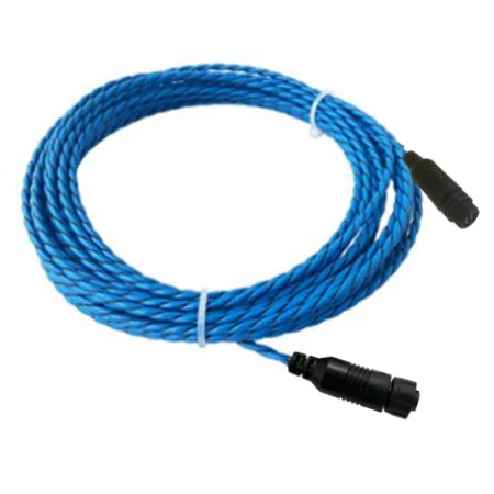
Cut to the run, terminated at both ends, packed on the reel.
Read next · Accessories · Design guides
Where the rope stops being the right device
The figures below are limits, not ratings. The rope works up to each boundary and stops being the right device after it, so each line also says what to do instead.
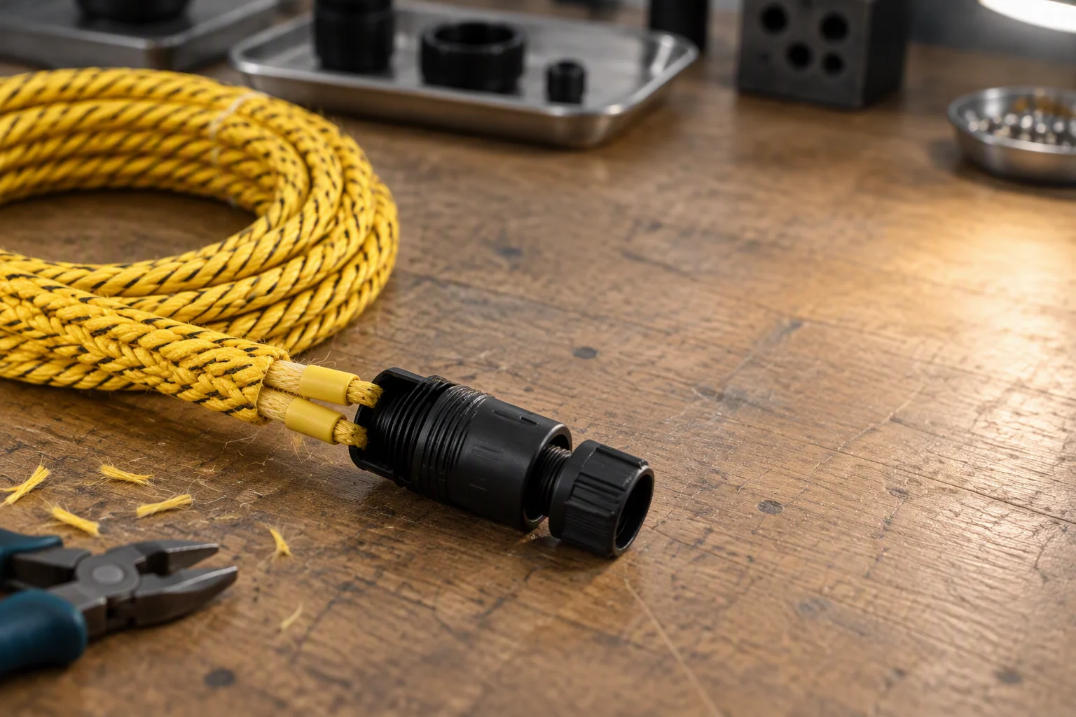
Both ends are terminated at the bench. The run length the controller is calibrated to is decided here, not on the slab.
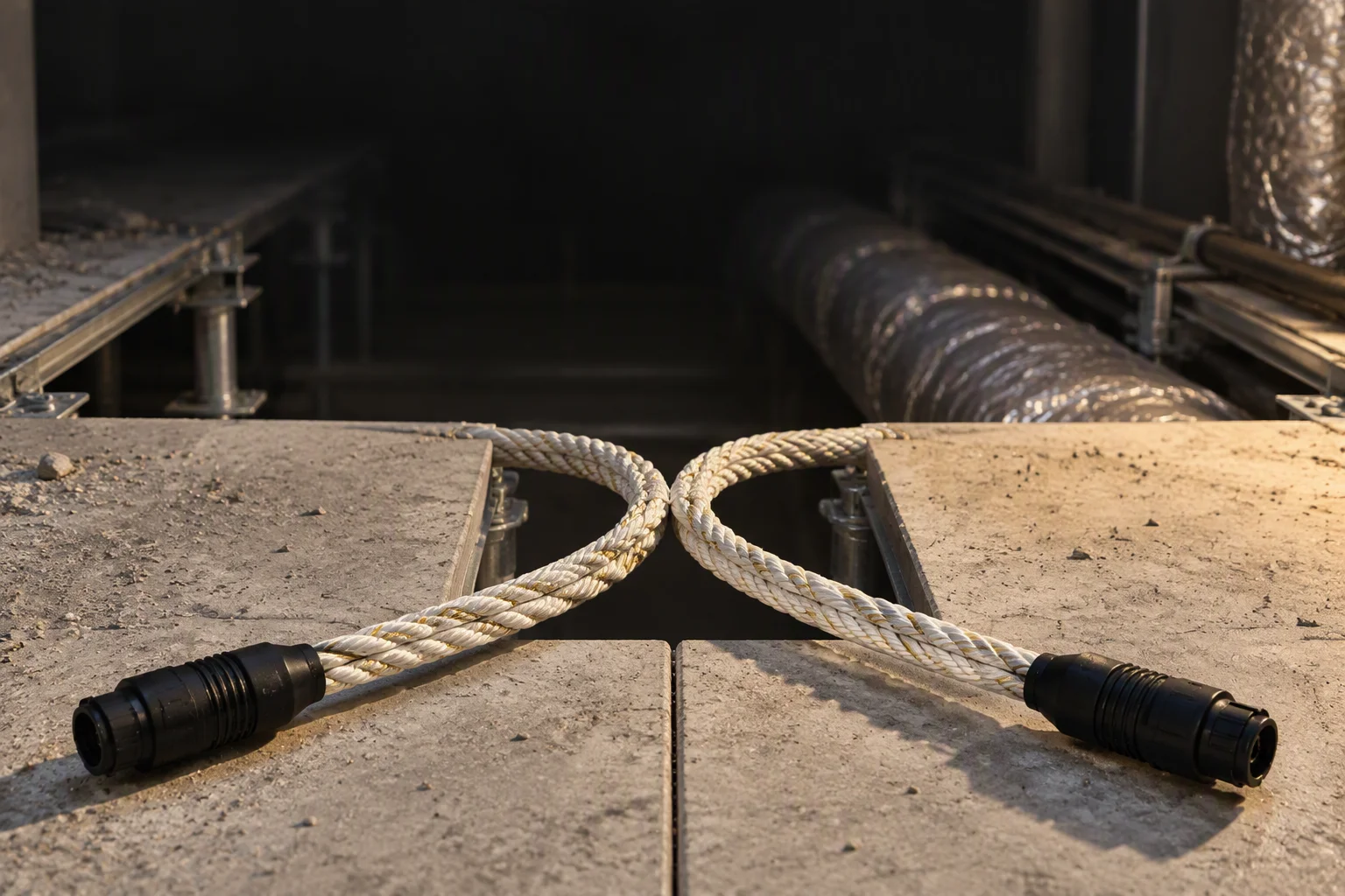
At the boundary the run is split rather than extended, and each half keeps its own address.
Read next · Controllers · Telemetry instruments
Specified wrong, it reports the wrong place
- Laid along the walk-round path instead of the pipe. It alarms where the technician already stands, and the wet joint stays dry.
- One channel across two aisles. The report names a wet tile between them, and both aisles have to be opened to find it.
- Plain twisted pair in a dusty trench. Dust and metal particles change the impedance too, so the channel alarms without water.
- Cut and re-terminated on site. The locating calculation is calibrated to the terminated length and every position reads short.
- A run past 500 m per channel. The far end falls outside the calculation and the last metres report as nothing at all.
- Waiting on the rope to stop the leak. It returns a position to 0.1 m; it does not close a valve or a pump.

Down the aisle: the rope covers the path the round takes, and not the pipe the coolant is in.
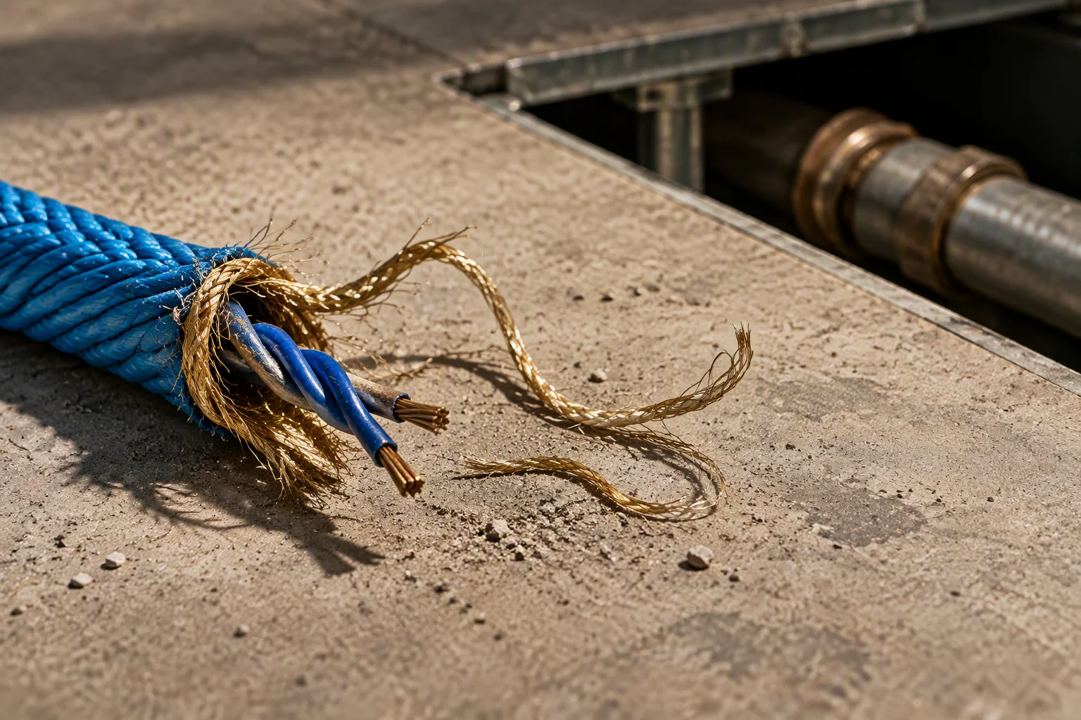
Cut on the slab: the length the controller was calibrated to is now shorter than the run.
Read next · Design guides · FAQ
What travels with the reel
The reel travels with paper. None of these documents is optional on a data centre purchase order, and all of them are issued in English.
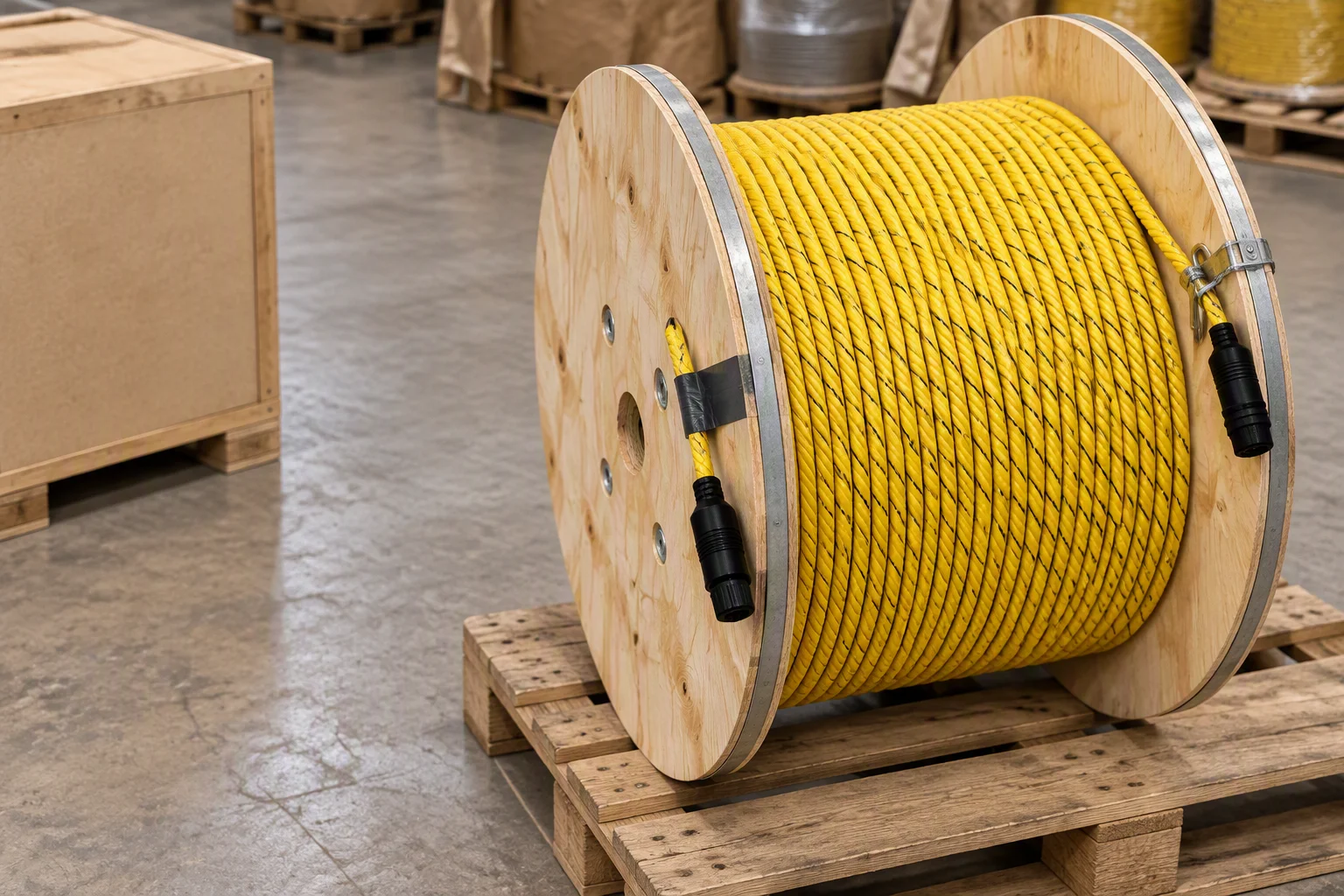
On the reel, cut to the run and terminated, with the length written on the certificate rather than the flange.
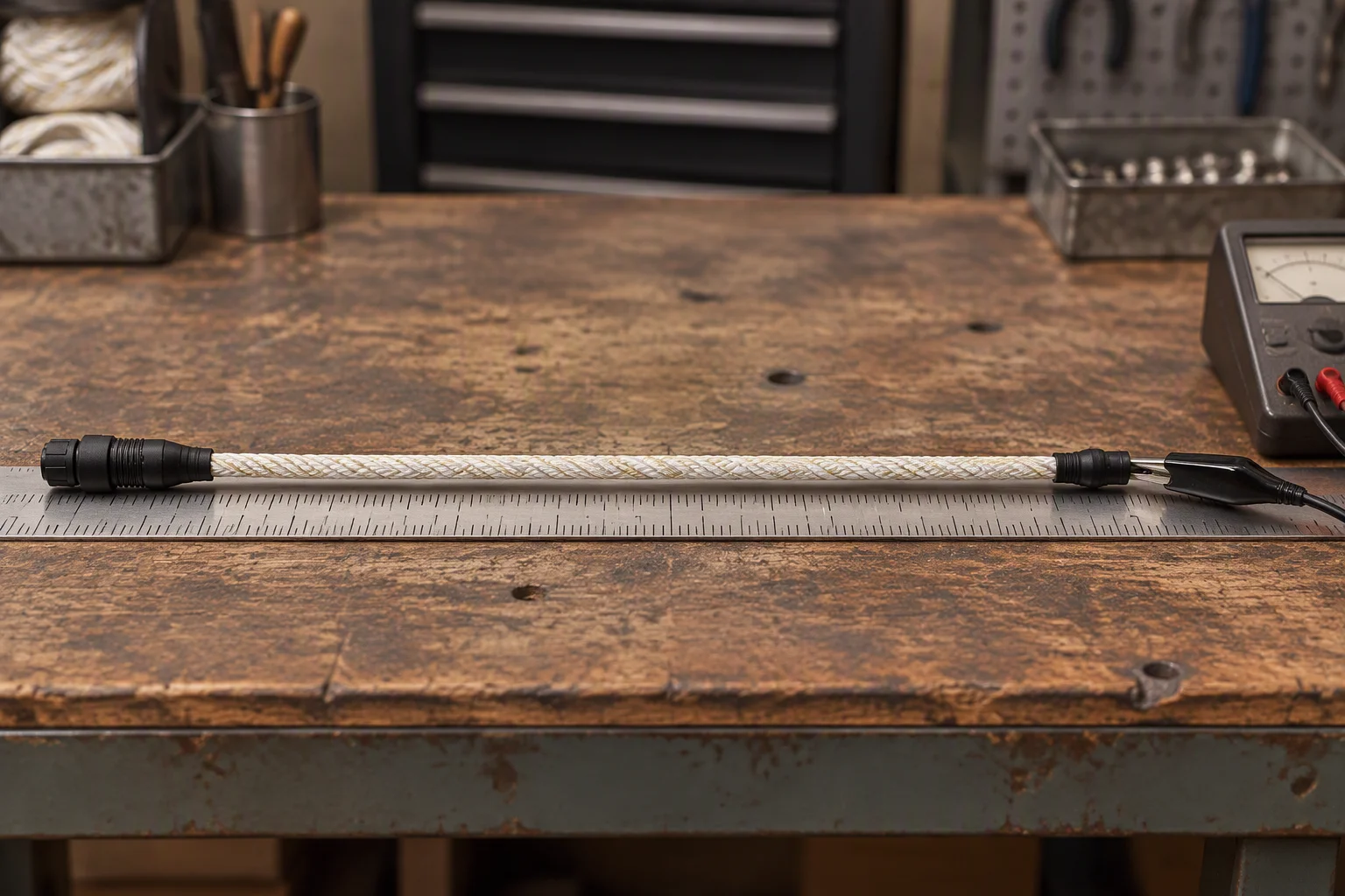
Every delivered length is measured and continuity tested before it is wound.
Read next · Quality & inspection · Supply network
Request the specification file
Four documents are held for this sheet. One request returns them attached, next business day.
- Specification sheet rope, module, end terminations
- EN 10204 3.1 material certificates metal parts
- Locating test report on request
- Outline drawings connector and module
One business day, with the file attached.
No other commitment is made on this sheet. Price, stock and lead time are not promised here.
If the form cannot send, this address takes the request instead: sales@ems-cool.com
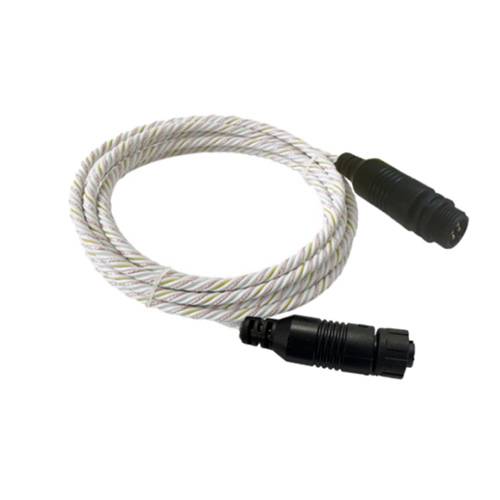
Twisted pair, both ends closed.
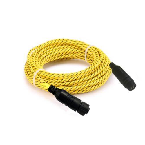
The woven jacket, terminated both ends.
