EMS-Trade
Cooling
Loop consumables

Document ECT-01 · REV C · ISSUED 2026-09 Six lines · 48 sheets

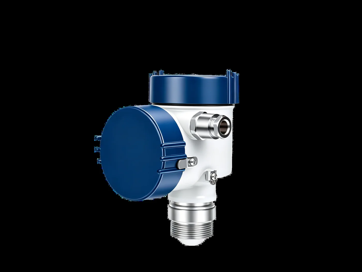
Differential pressure transmitter photographed against a black ground: a blue-capped white housing on a stainless process connection, with a cable gland on the side
FIG 01 · differential pressure

Pressure instruments for the liquid cooling loop

Differential pressure across the filter is the reading that moves first. This sheet gives the range and the wetted material, what is held, how it is packed, and where the shipment leaves from.

Request the specification file One business day, with the file attached

Change-out differential 0.5–0.7 bar Loop pressure 1.38 MPa Burst ≥ 5.5 MPa Media −40 to +99 °C

01

Range against reading point, and the cells that stay empty

Section 01 · the matrix · two cells per tapping point

Four points on a loop carry a pressure worth reading, and each one takes two grades: something that shows the value where the pipe is, and something that sends it to a panel. The grid below is the two of them against the four points, and where a grade is not fitted the cell says why rather than being left blank.

Only one of the four is worth a transmitter on every site: the differential across the filter. The other three are ordered when the site runs unmanned or when the contract asks for a logged record, and not otherwise.

Four pressure tapping points on one loop, with the filter differential band marked Supply header, filter inlet to outlet, pump discharge and reservoir head are marked along the loop. The filter differential is marked from 0.5 to 0.7 bar. supply return 0.5–0.7 bar at change-out 01 02 03 04 Supply Filter Δ Discharge Reservoir
0.5–0.7 bar Filter Δ · signal
4–20 mA Filter Δ · to the BMS
1.38 MPa Supply · signal
not fitted Supply · no transmitter
1.38 MPa Discharge · signal
not fitted Discharge · no transmitter
static head Reservoir · signal
not fitted Reservoir · no transmitter

Why the empty cells are empty · a transmitter on the supply header repeats what the discharge reads within the drop across the loop, and the drop is not the number anybody acts on. A transmitter on the reservoir head measures a level that the level sensor already reports. The filter differential is the one that changes with time; the others only change when something has already gone wrong.
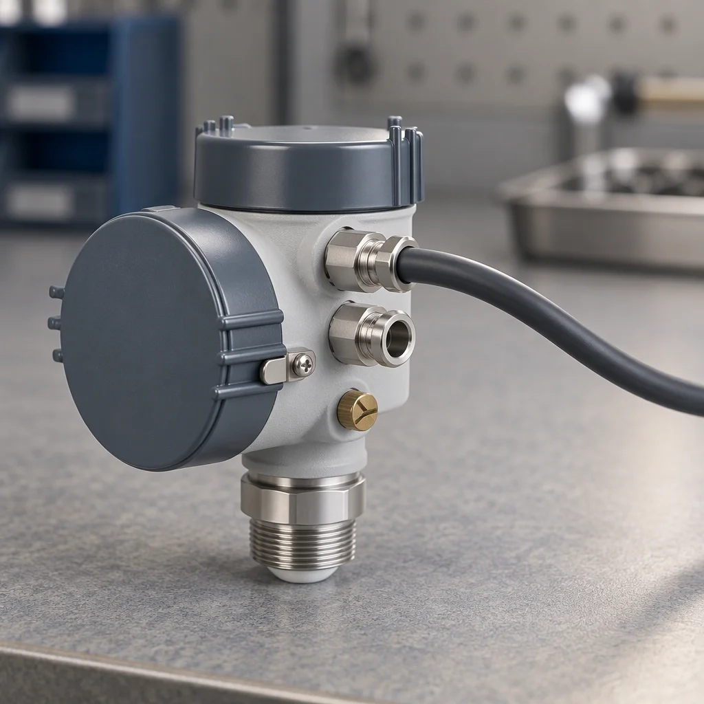
A differential pressure switch on a bench, a small grey housing with two impulse ports and a set screw under a cap, its scale plate turned away from the camera
FIG 02

Switch: one contact, set once, no value on the wire.
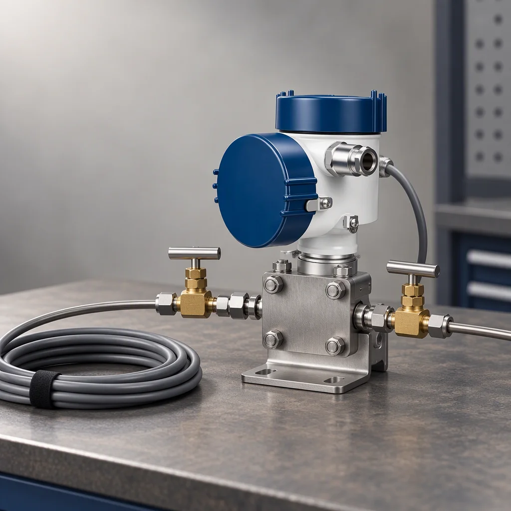
A differential pressure transmitter with two impulse tubes connected by small valves, resting on a bench with its cable tail coiled beside it
FIG 03

Transmitter: the value, continuously, on a 4–20 mA loop.
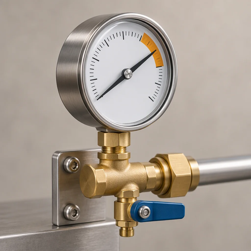
A bourdon gauge on a manifold with its face angled towards the camera, a needle resting against a marked band on the dial and a small drain valve below it
FIG 04

Gauge: read by whoever is standing there, and by nobody else.

Read next · Coolant filtration · Telemetry · Design guides

02

The parts, photographed

Section 02 · four parts · as shipped

Four parts from the same loop, photographed on the bench rather than rendered. The differential transmitter is the one this sheet is about; the other three are what it lands between.
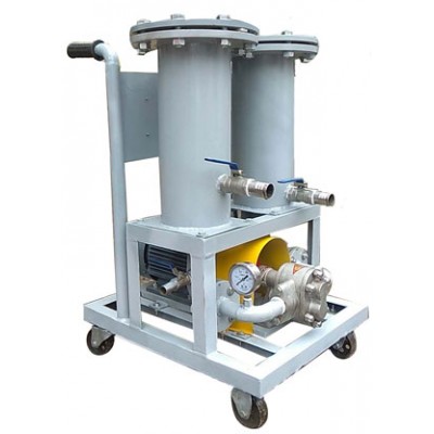
A filter trolley on a wheeled frame: two grey cylindrical housings with flanged tops, blue-handled ball valves, a pump below and a round gauge on the outlet
PL 01 Filter trolley Two housings · gauge · bypass valve
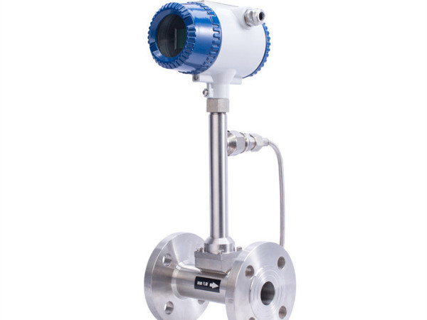
Flanged in-line flow meter with a blue-capped transmitter head on a stainless body, photographed on a white ground
PL 02 Flow meter, flanged Stainless body · the other reading at the same tapping
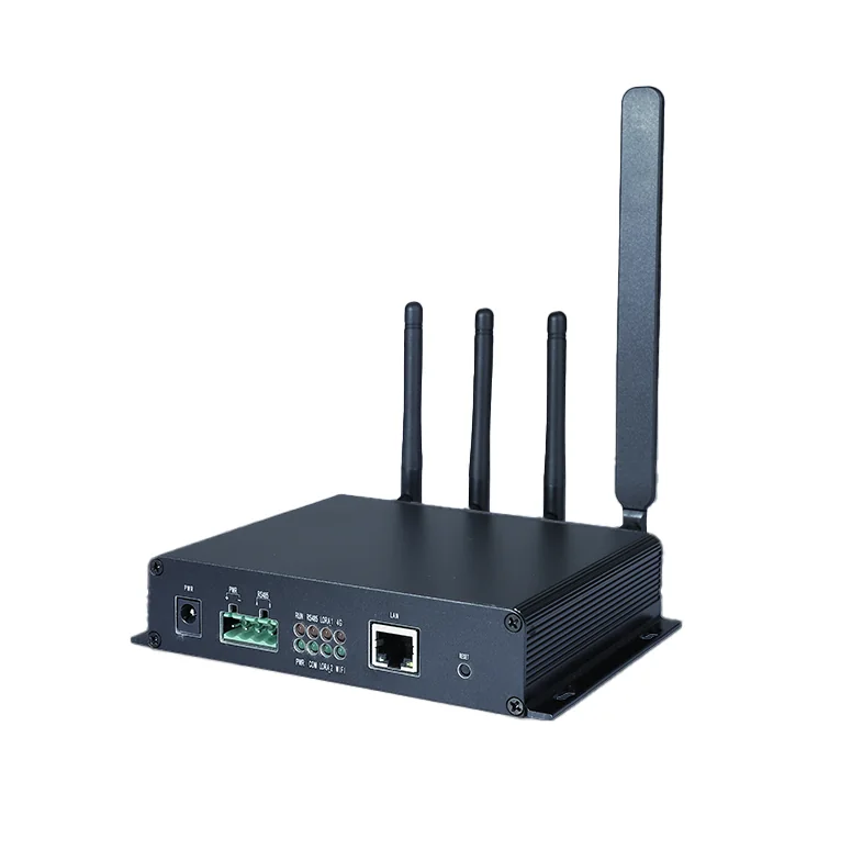
Black finned gateway with four antennas, a green screw terminal block, a LAN port and a DC power socket along its front edge
PL 03 Gateway Terminal block · LAN port · four antennas
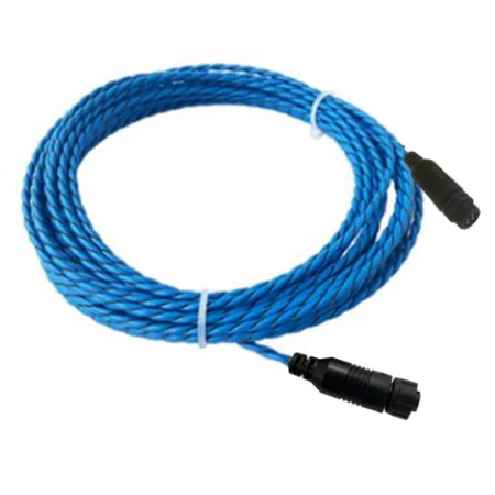
A coil of blue twisted-pair sensing cable with two black end connectors, photographed on a white ground
PL 04 Sensing cable Laid under the same run, for the leak that follows a pressure loss

Read next · Quality & inspection · Supply network · Projects

03

Minimum, samples and the days between order and shipment
Section 03 · order · numbers, not adjectives

Minimum order
one carton on standard ranges; 500 m on custom lengths of the sensing run
Samples
7–10 days, with the first-article inspection record attached
Production
25–35 days for a scheduled batch; a 15 day slot is opened when the parts are in stock
Payment
T/T 30% with the order and 70% against the bill of lading copy; L/C at sight on large batches
Batch record
incoming inspection per batch, kept under the batch number printed on the carton
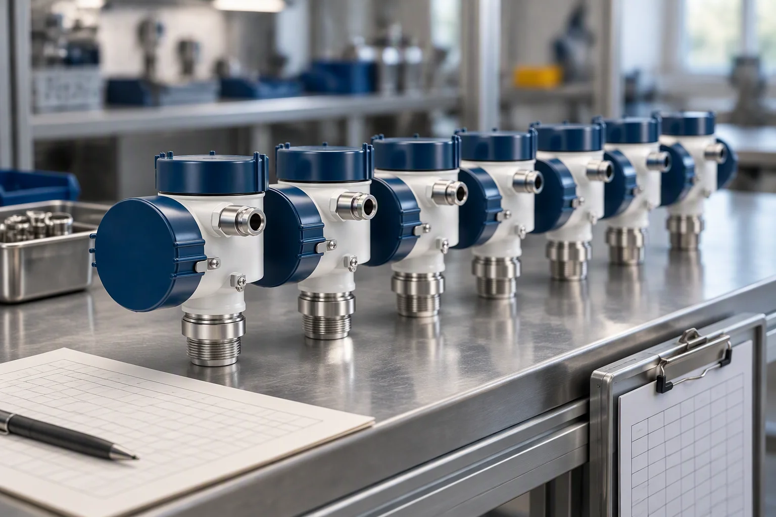
Transmitters laid out in a row on an inspection bench with a batch card in front of them and an inspection record clipped to the side of the bench
FIG 05

A batch is inspected as a batch, and the number follows it out of the building.

A production board on a workshop wall with orders chalked in columns and a strip of dates along the top, a hand not in frame
FIG 06

A scheduled batch is a date, not an estimate. It is the reason 25–35 days is quoted rather than a range.

Read next · FAQ · Fill & flush · Contact

04

Packing and the documents in the carton

Section 04 · packing · item by item

Packing schedule · what each part travels in, and what is in the carton with it
Part Packed in With it Note
Transmitter Foam-lined carton Certificate, outline drawing Foam cut to the part, not loose fill
Gauge and manifold Foam-lined carton Outline drawing The dial is not left against a hard face
Filter housing Export crate EN 10204 3.1 certificate, outline drawing Heat-treated timber to ISPM 15
Sensing run Wooden reel Termination sheet Terminated at both ends before it leaves the reel
Spares bag Carton Seals, ferrules, terminals Ordered with the batch, not after it

Certificates · EN 10204 3.1 on the metal parts that see the coolant, per batch, with the batch number on the carton. The system certificate behind the batch record is ISO 9001. Declarations for the electronics are CE marking, RoHS and REACH.
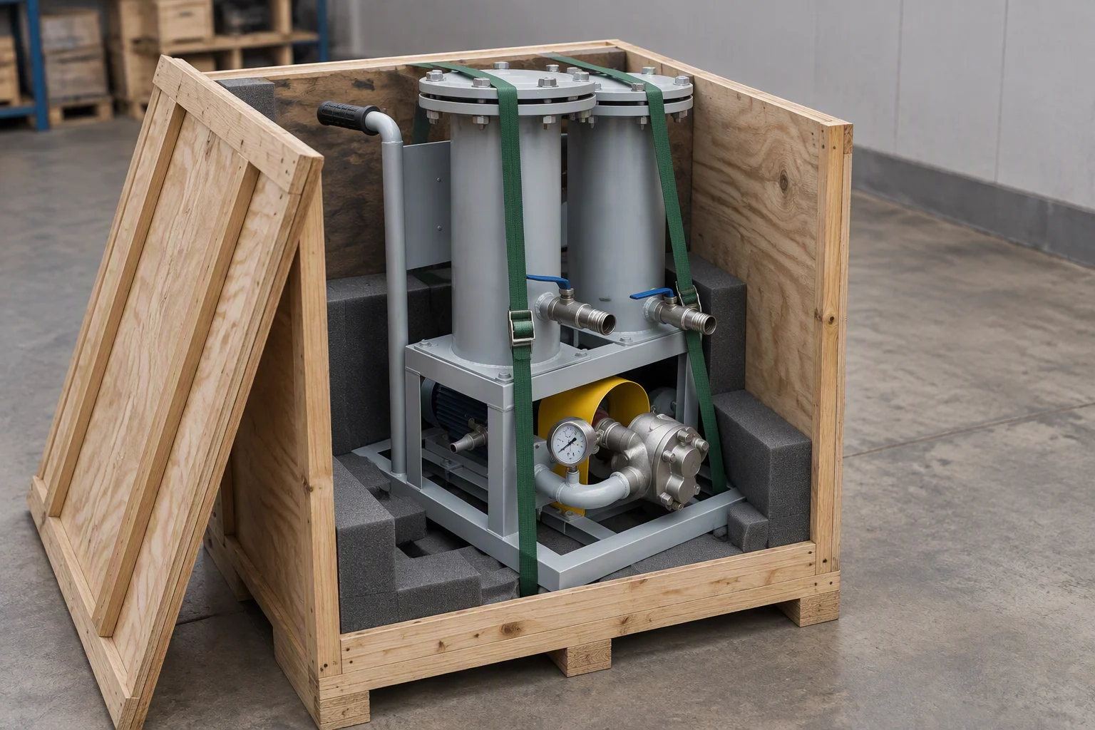
An open export crate with a filter housing standing in a shaped foam cradle, the lid leaning against the crate and strapping laid across the top
FIG 07

Housings travel in a crate with a shaped cradle, on heat-treated timber.
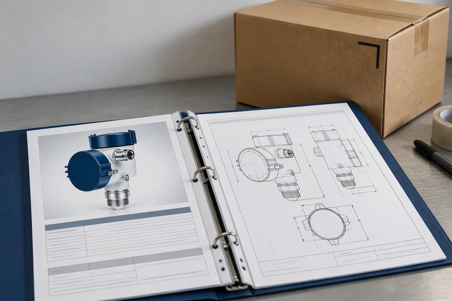
A document folder open on a bench with a material certificate on one side and an outline drawing on the other, a carton in the background with a marked corner
FIG 08

The certificate and the drawing go in the carton, not into an email sent afterwards.

Read next · Quality & inspection · Legal · Contact

05

Where the goods come from, and the line they leave on

Section 05 · supply network · no factory of ours in the frame

We are a supply network, not a factory. The instruments on this sheet are built on partner lines we have bought from for years, and every batch passes incoming inspection before it leaves Shenzhen. What the network gives a buyer is one interface, one document set and one shipment, instead of four suppliers who each ship against a different specification.

Six product lines, one document set, one port. The lines behind them are partner lines.
ISO 9001 Batch record Incoming inspection per batch, kept under the batch number.
EN 10204 3.1 Material certificates On the metal parts that see the coolant, not on the packing.
25–35 days Production lead time Samples in 7–10 days, by air, with the inspection record.
FOB Shenzhen Incoterms CIF and DDP quoted on request; documents in English.
ISPM 15 Export packing Heat-treated crates, cartons inside, reels for the sensing run.
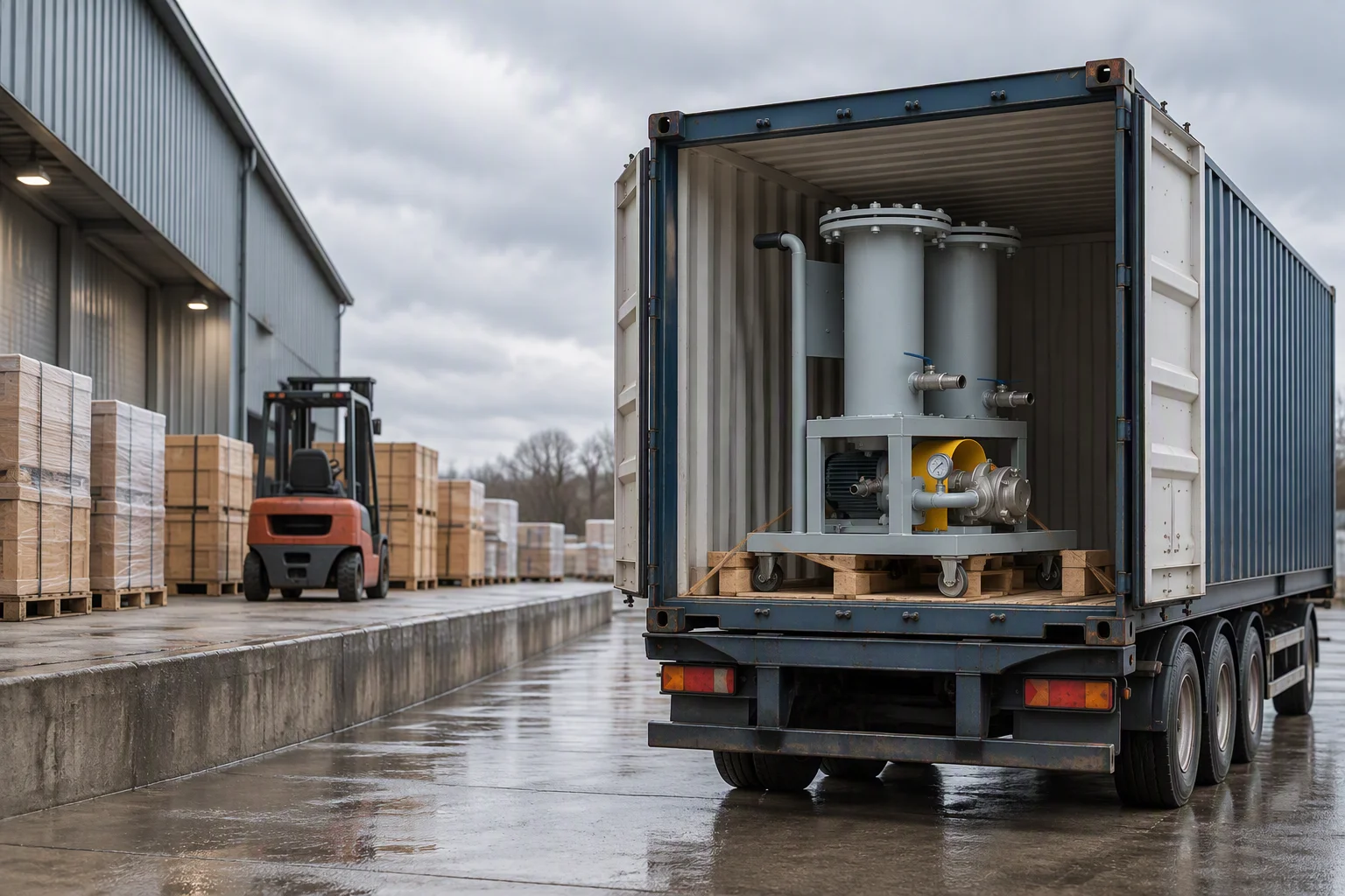
A loading yard outside a workshop with a container on a trailer, pallets of crated equipment along the dock and a forklift facing away
FIG 09

One dock, one set of documents, whether the batch is instruments or hose.
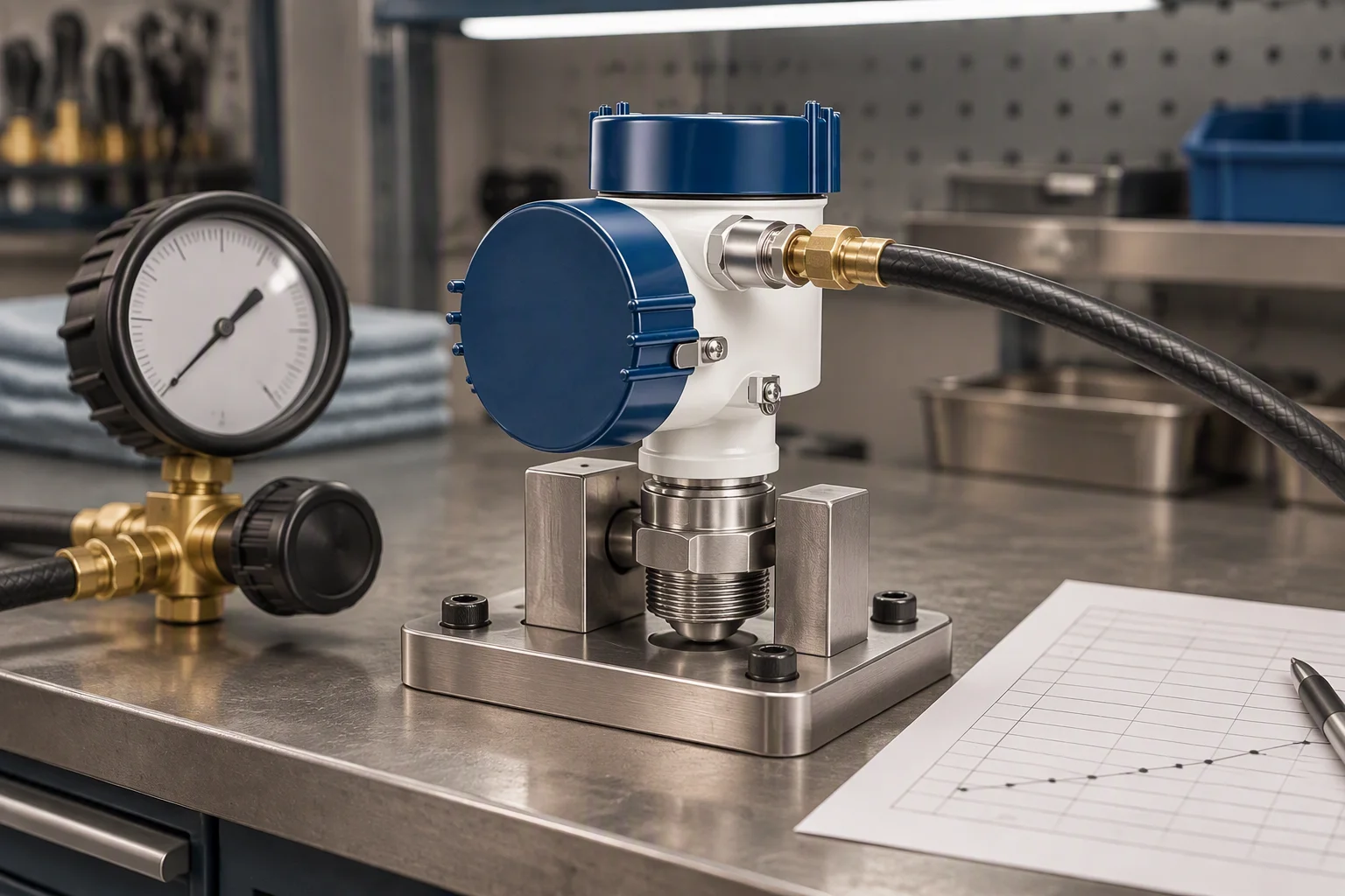
An incoming inspection bench with a transmitter on a fixture, a gauge and a pressure source connected to it, and a sheet of results beside the fixture
FIG 10

Incoming inspection is the step the network is held to. It happens here, not at the partner line.
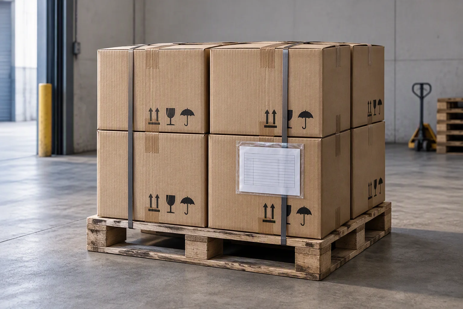
Marked export cartons on a pallet with shipping marks stencilled on the sides and a packing list slipped into a document pouch on the front carton
FIG 11

Marks and the document pouch go on at packing, so nothing has to be re-opened at the port.

Read next · Supply network · About · Capabilities

Document request

Four documents are held for this sheet. Tick the ones you need.

Tick a document, give the range and the quantity, and the file comes back attached.

The only promise on this page

One business day, with the file attached.

Nothing else on this sheet is promised. Price, stock and lead time are not promised here.
If the form cannot send, the address below takes it instead: sales@ems-cool.com. A request is never accepted and then dropped.
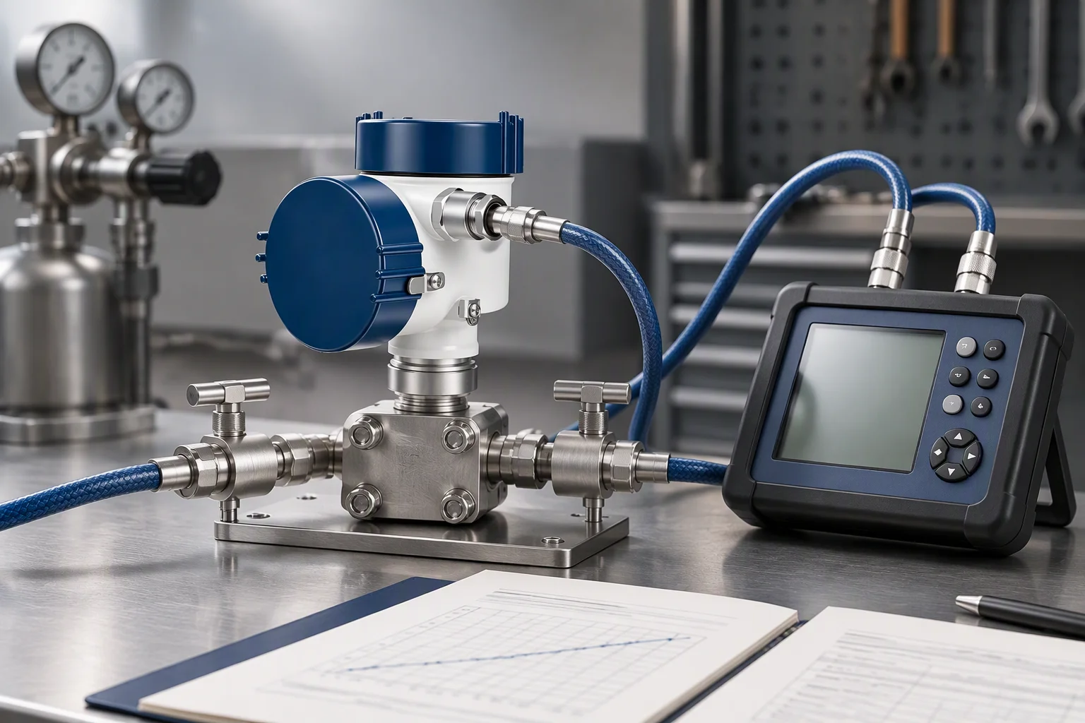
A differential transmitter on a test bench with its two impulse ports connected to a pressure source and a digital reference beside it
FIG 12

Checked against a reference before the certificate is signed, not after.
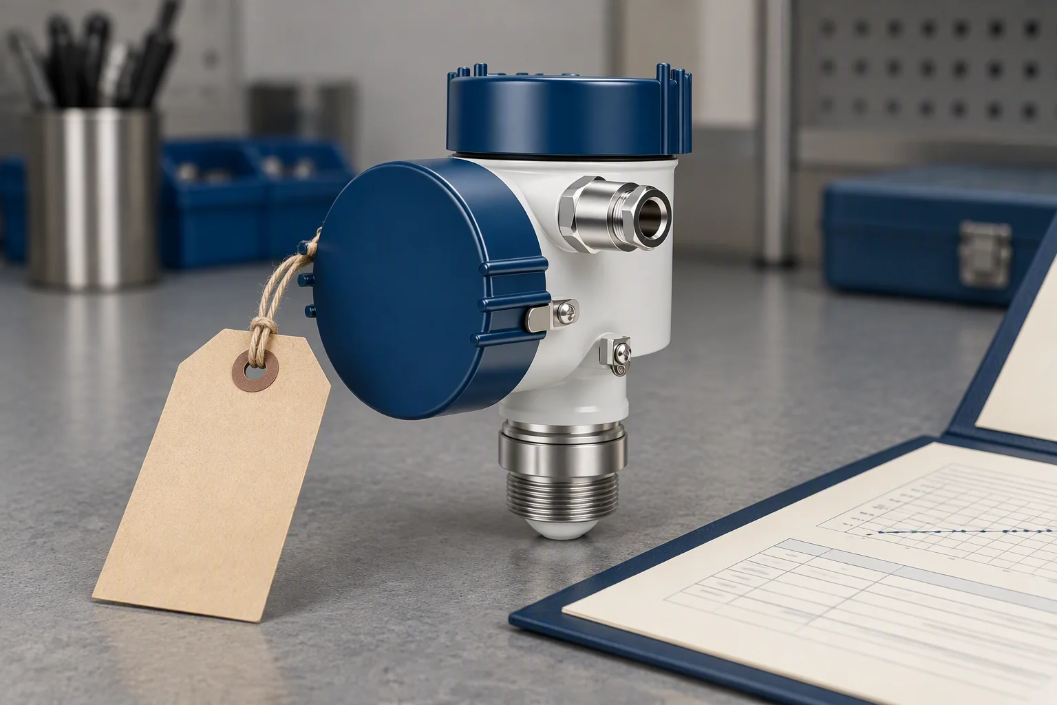
A tag wired to a transmitter on a bench with the range and the batch written on it, the certificate folder open beside the instrument
FIG 13

The tag carries the range and the batch. Both are on the certificate in the carton.