
Eight ways a loop seal degrades before it drips
A loop seal almost never fails as a burst. It is lost slowly, through eight mechanisms that each leave a different mark on the seat and each open in a different window. Seven of the eight are invisible from outside the joint, which is why a seal that has been weeping for a month still reads as healthy.
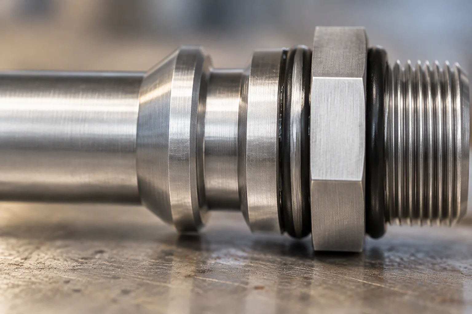
One seat, one ring, one bright band. The band is where the joint is actually sealing, and it is the only part of the assembly that has to be right.
A seal is lost long before it drips
The claim is narrow enough to be argued with. A joint that drips has been degrading since the first thermal cycle, and by the time there is a drop under it the mechanism has been readable on the seat for months. The drop is not the failure. It is the last of eight mechanisms finishing its work.
The consequence is that a seal is not maintained by watching for drips. It is maintained by reading the seat at a window that was going to happen anyway: the one in which a coupling is opened, a rack is moved, or a filter is changed. Nothing here needs new access or a longer outage.
Check it this way: open one joint that has been in service across a full season and photograph the contact band. If the band is bright and continuous, the joint was healthy and the photograph is your baseline.

At bench magnification the contact band reads as a flat, slightly glossy track.
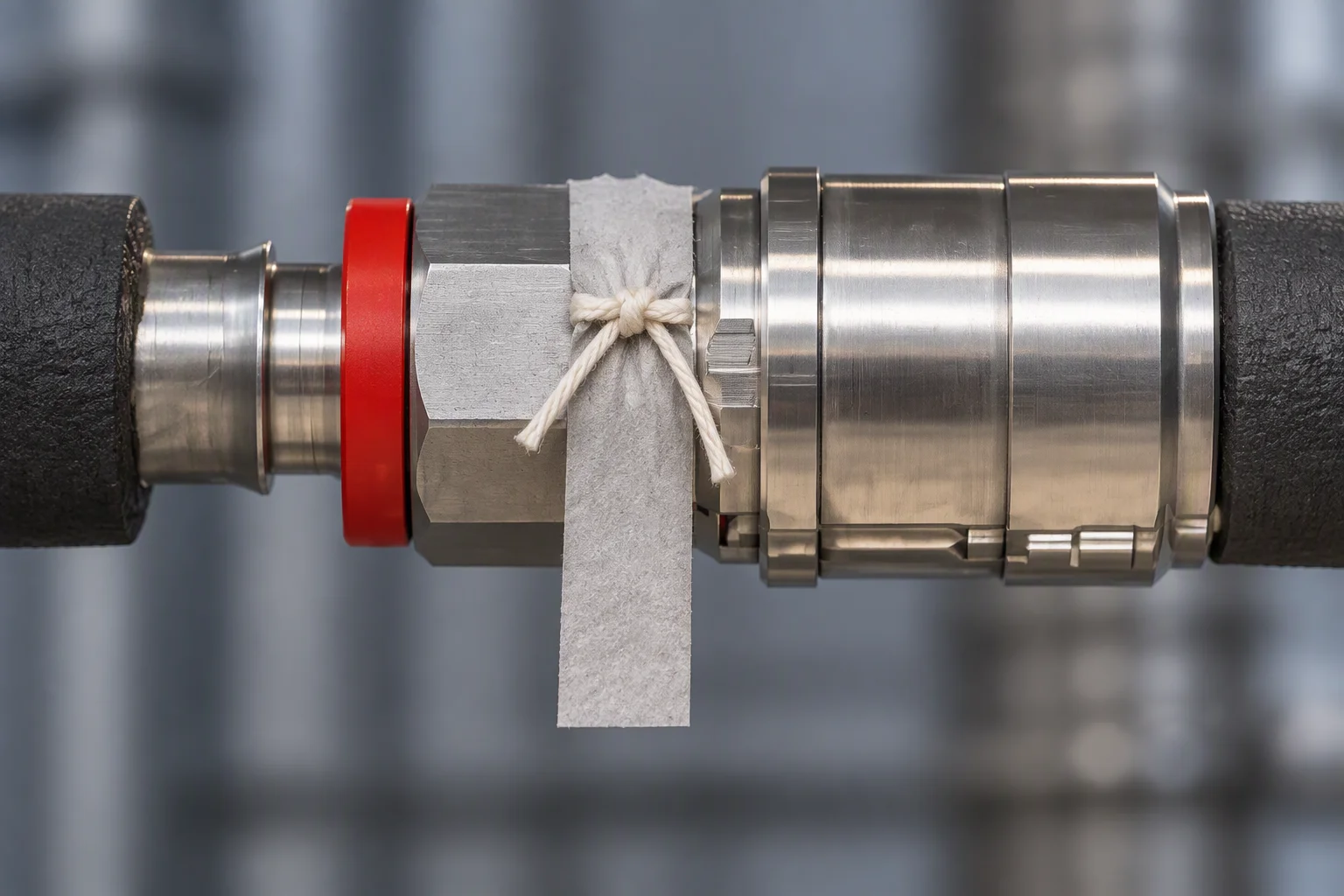
A dry paper band is still the cheapest moisture witness on a loop, and it dates the onset for free.
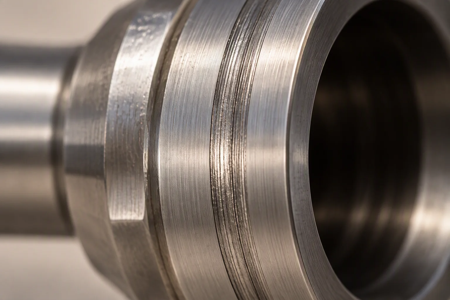
The turned finish is the datum. Anything polished across it is the seal doing its work.
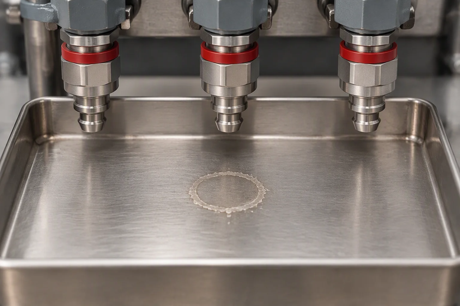
A dried ring mark with clean metal around it is a joint that sealed itself again. That is the mechanism that hid the problem.
What is happening inside the groove
Key
- 1 ·The groove. Its depth sets the squeeze the ring is given, and it does not change over the life of the joint.
- 2 ·The elastomer cross-section. Every mechanism here acts on the same small volume of material.
- 3 ·The contact band on the metal face. Bright and unbroken is healthy; matt or fretted is not.
- 4 ·The bore side. Coolant reaches the ring here, so chemical attack shows on this face first.
- 5 ·The extrusion gap. Working pressure is 1.38 MPa and burst is above 5.5 MPa; the gap is what the elastomer bridges at both.
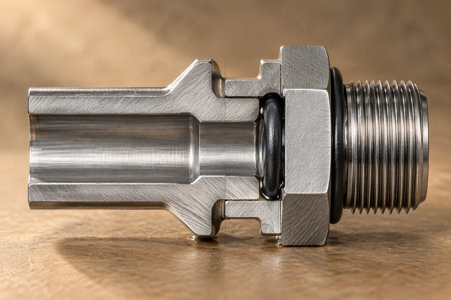
Cut lengthways, the groove and the ring are one shape. None of it is visible from outside the joint.
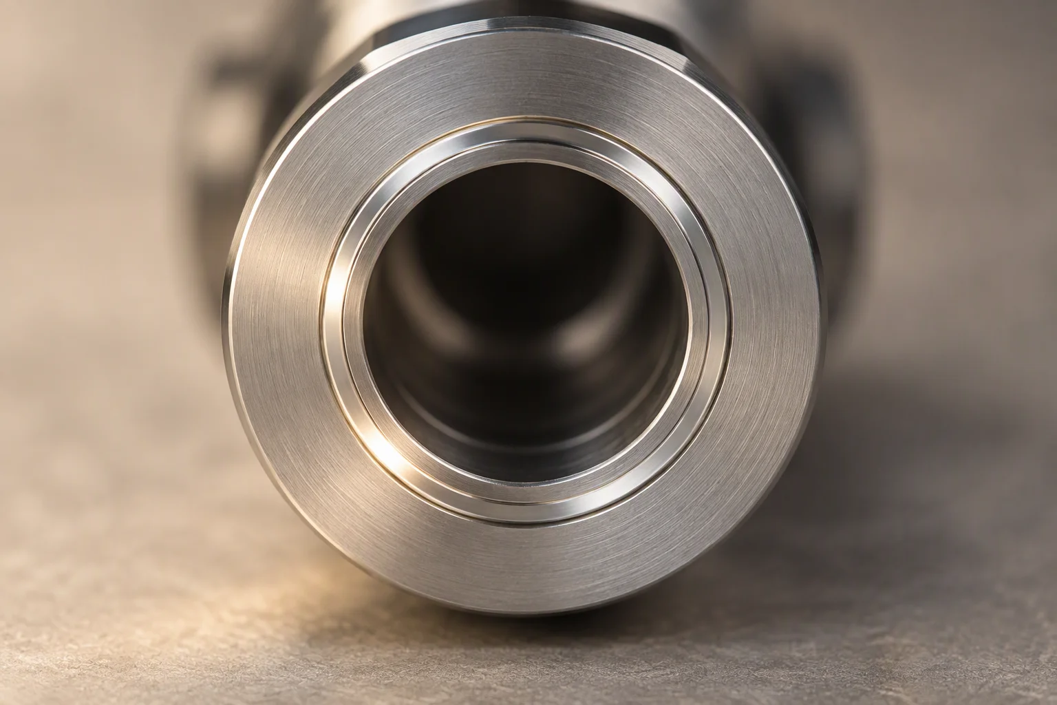
A healthy band is narrow, unbroken and slightly glossy. A band that has gone matt and wide has stopped concentrating load.
The drawing is a section, not a scale model: proportions are set so the groove, the ring and the gap read together at page width. The dimensions a purchase turns on are in the schedule below.
The eight mechanisms, one schedule
Compression set
The ring takes a flat where it was squeezed and stops pushing back. Re-torquing helps once, then stops helping, which is the point at which most joints are first noticed.
From the first thermal cycles
Thermal hardening
The cover loses elongation and crazes along the contact band. The ring reads stiff rather than springy between gloved fingers, and it no longer follows the metal as the joint cycles.
At the top of the range
Swell and shrinkage
Volume follows glycol concentration. A swollen ring grips the groove and will not come out clean; a shrunk ring has already lost its squeeze and cannot be re-used.
Within weeks of the change
Attack from a spent package
Surface crazing and a colour shift, always on the fluid side of the ring. By the time this shows, the inhibitor package holding the fluid back has already gone.
From the third year
Particle embedment
Solids press into the elastomer and sit proud of the contact band, lifting the sealing line off the metal in local spots. The count that matters is the one at the joint, not at the tank.
As the count rises
Extrusion into the gap
A nibbled edge on the low-pressure side, matching the clearance it was pushed into. The one mechanism driven by pressure rather than by time.
Under sustained pressure
Spiral twist
A helix in the ring that was not there when it was fitted, from an installation that rolled the ring in instead of laying it in. Fitting damage, not service damage.
Invisible until opened
Seat damage carried in
A nick, a tool mark or a scratch on the metal that prints itself onto every replacement ring. Replacing the ring without dressing the seat reproduces the leak on the same schedule.
Immediately, and permanent
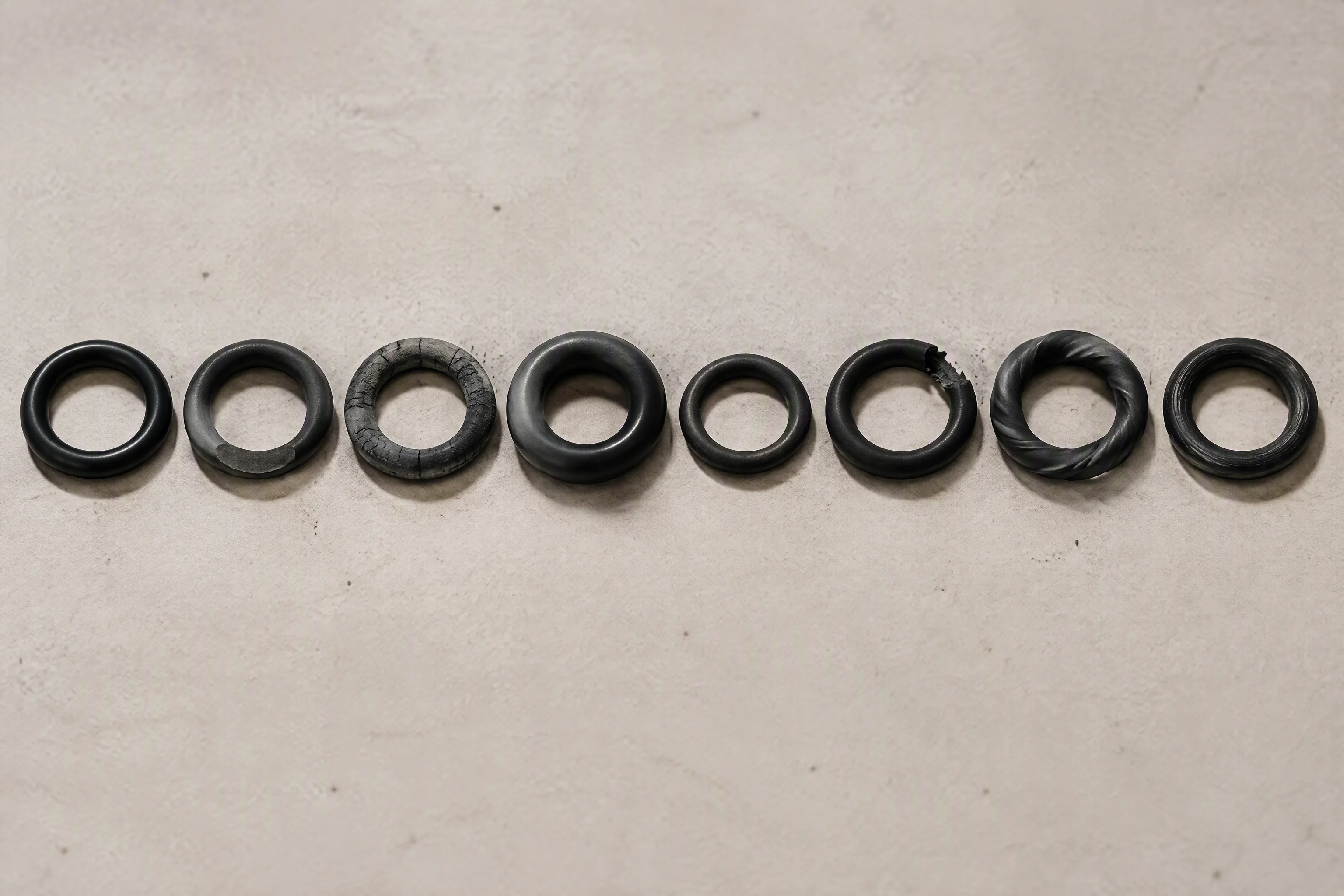
Eight rings, eight signatures. Read as a set, the schedule stops being a list of failure modes and becomes a way of sorting what came out of a joint.
The parts this note is written against
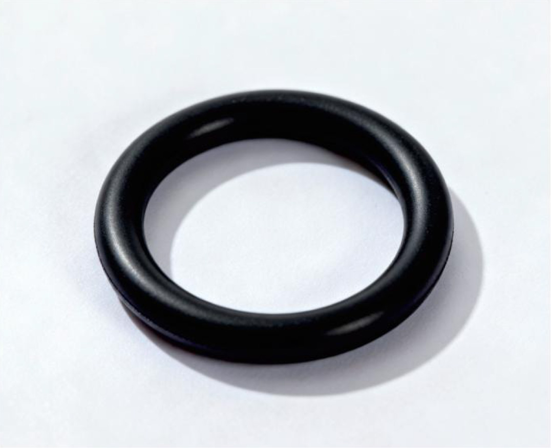
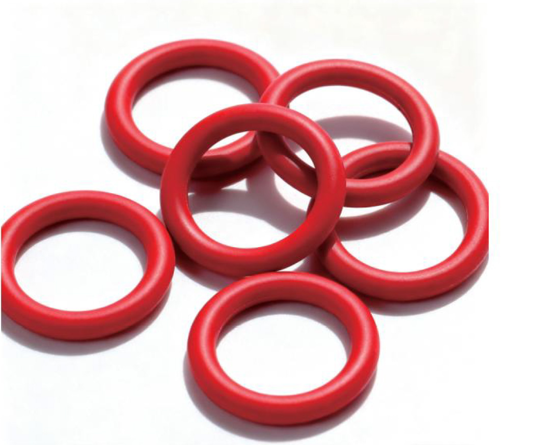
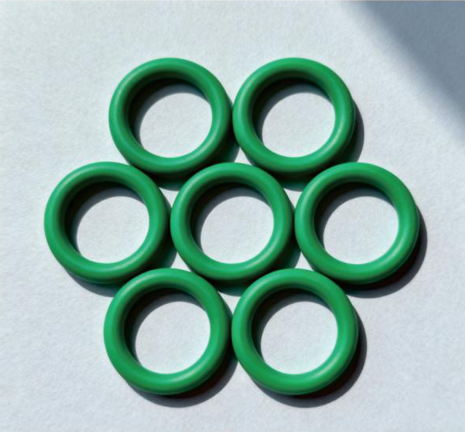
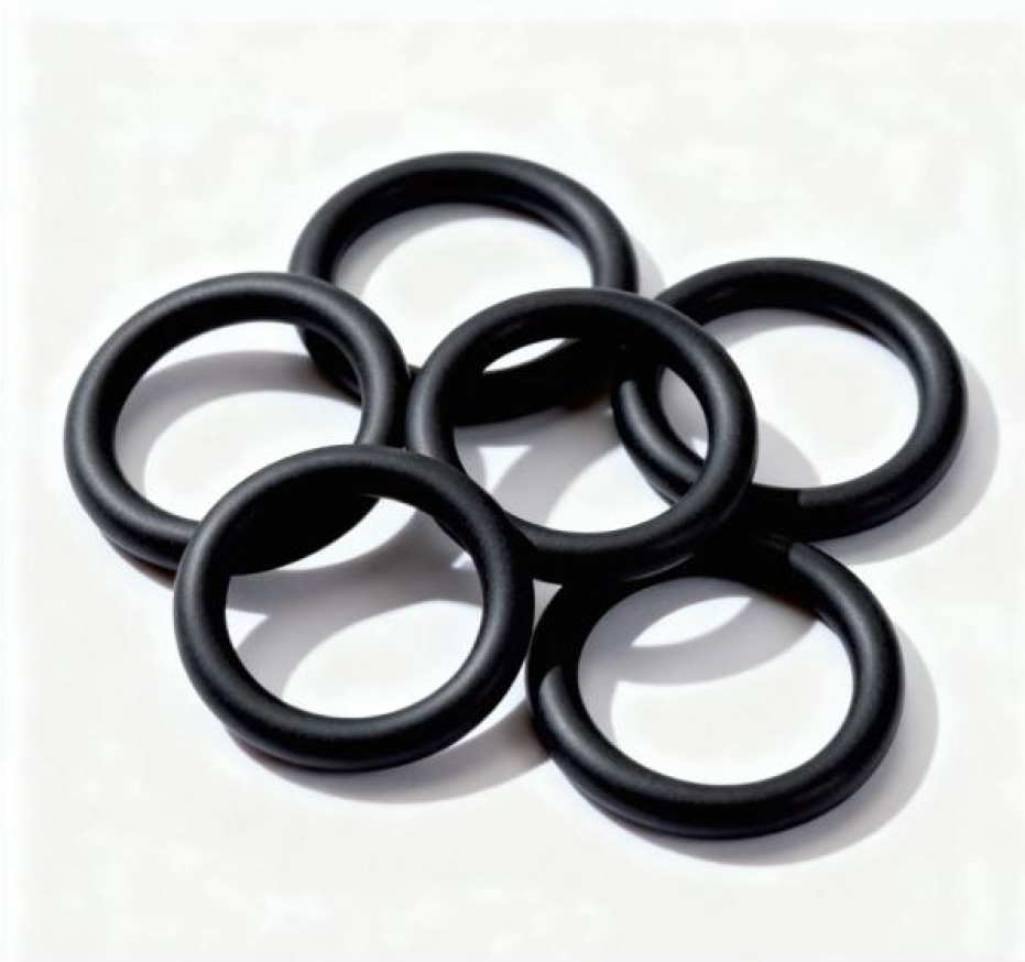
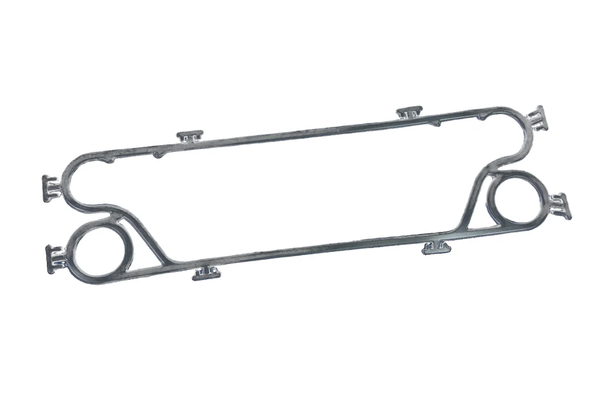
Six parts from the six lines on this site, held as the physical reference for the schedule above. They are the subjects of the figures, not a range: fittings and seals schedules what is held.
The figures that decide it
| Item | Figure | Value | Unit | Condition it holds under |
|---|---|---|---|---|
| 01 | Service temperatureWhole joint | −40 ~ +99 | °C | The narrower of the two published ranges. The supplier range reaches higher; the loop figure is the one a rack sees. |
| 02 | Working pressureAt the joint | 1.38 | MPa | About 200 psi. This is the figure that drives extrusion into the gap, mechanism M6. |
| 03 | Burst, minimumAssembly | ≥ 5.5 | MPa | Tested as crimped, not as a bare hose length. It is the ceiling the seal is never meant to see. |
| 04 | Cleanliness at the jointLoop target | ISO 4406 | 17/15/12 | The particle figure behind M5. Counts taken at the tank flatter the number the seal actually sees. |
| 05 | Fine filtration stageElement | 1 | µm | Absolute rating, on the loop side of the joint. The ladder runs to 100 µm at the coarse end. |
| 06 | Flame rating of the coverHose | UL 94 | V-0 | On the outer cover of the hose the seal sits in, not on the elastomer itself. |
| 07 | Material certificateMetal parts | EN 10204 | 3.1 | Traceable to the heat the bar came from, which is what makes a seat replacement checkable. |
| 08 | Glycol in the facility supplyFluid | 20 | % | At or under this figure for a water based loop. Concentration error is mechanism M3, and it shows within weeks. |
Eight figures, each written with the condition it holds under. A value without its condition is not a specification.
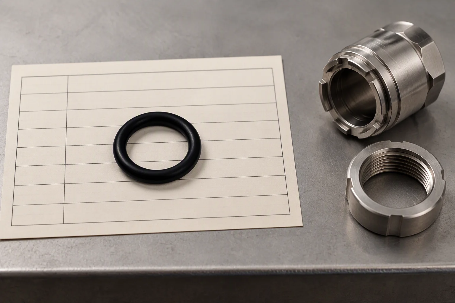
The eight mechanisms are only useful as a schedule if the joint they came out of is written down beside them.
What to do at the next window
Measure the groove, not the ring
A worn groove changes the squeeze every replacement ring is given. The ring is the part you can buy; the groove is the part that decides whether buying it helps.
Keep one joint as a reference
The same joint, opened every time, photographed the same way. One reference joint tells you more about a loop than eight random ones spread across it.
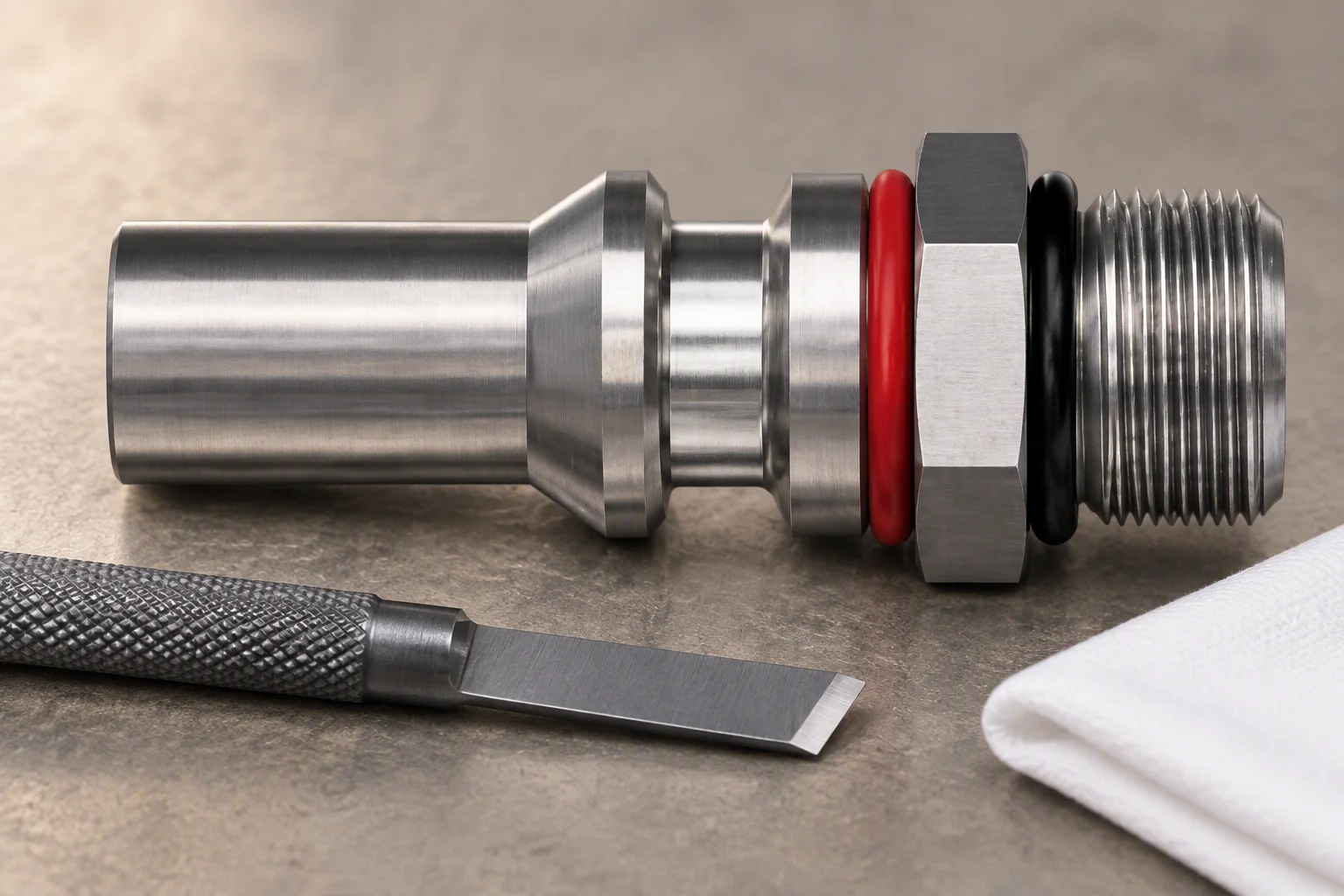
Dressing the seat is a two-minute action, and it decides whether the next ring lasts as long as the last one did.
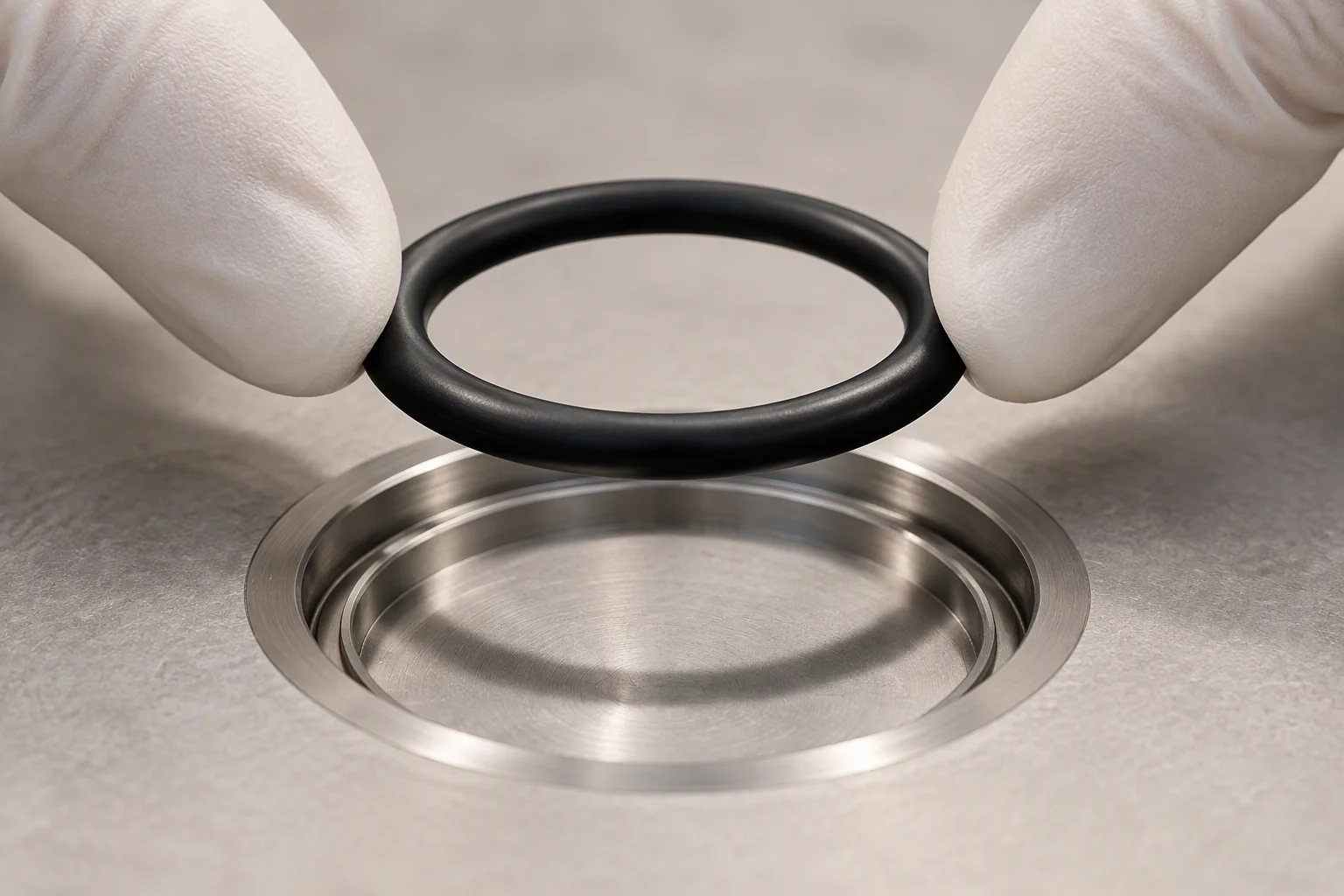
Level and even. A ring that goes in flat cannot carry a helix into service.
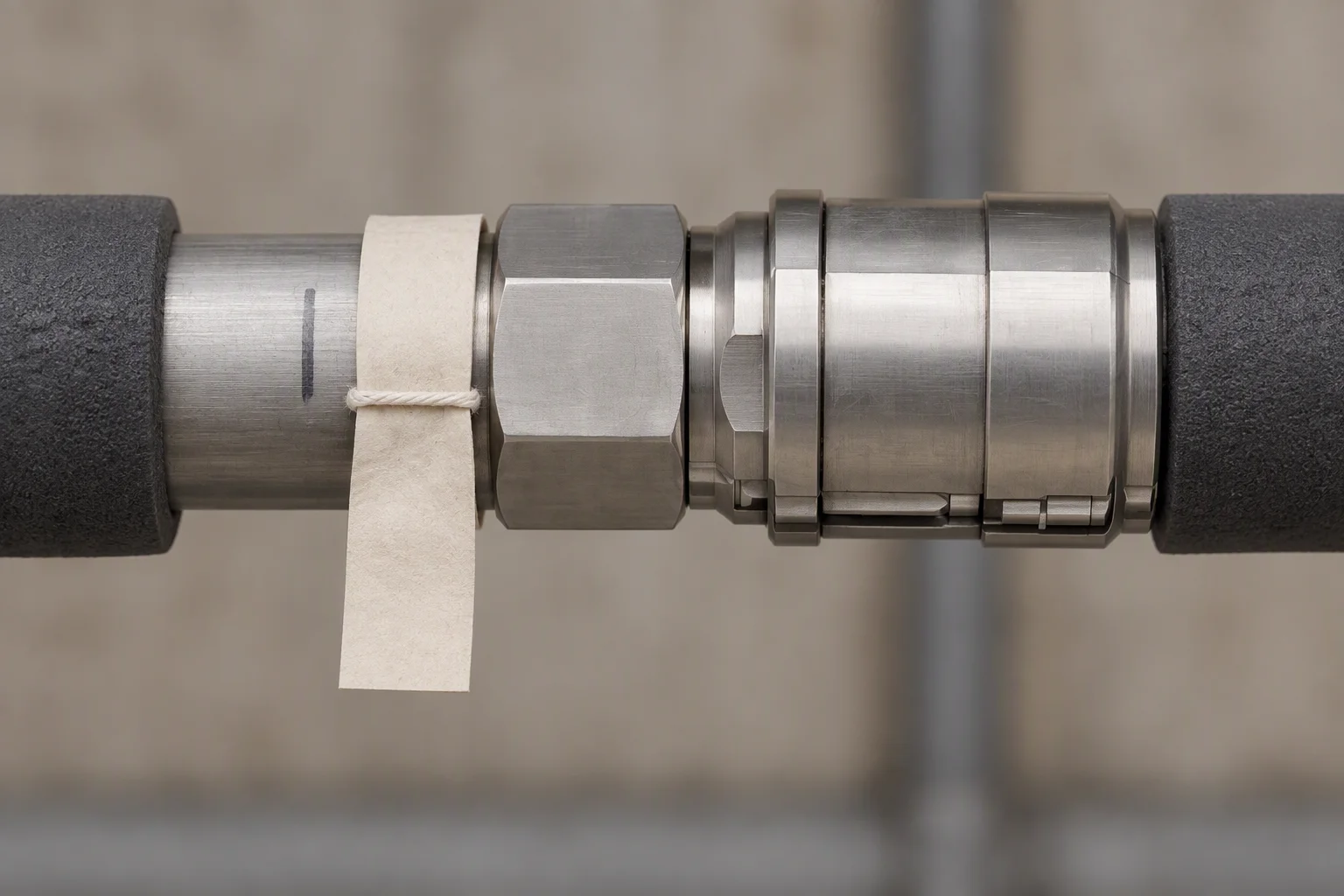
The band stays on until the joint is opened. Its condition when it comes off is the only free history a loop gives you.
What this note does not cover
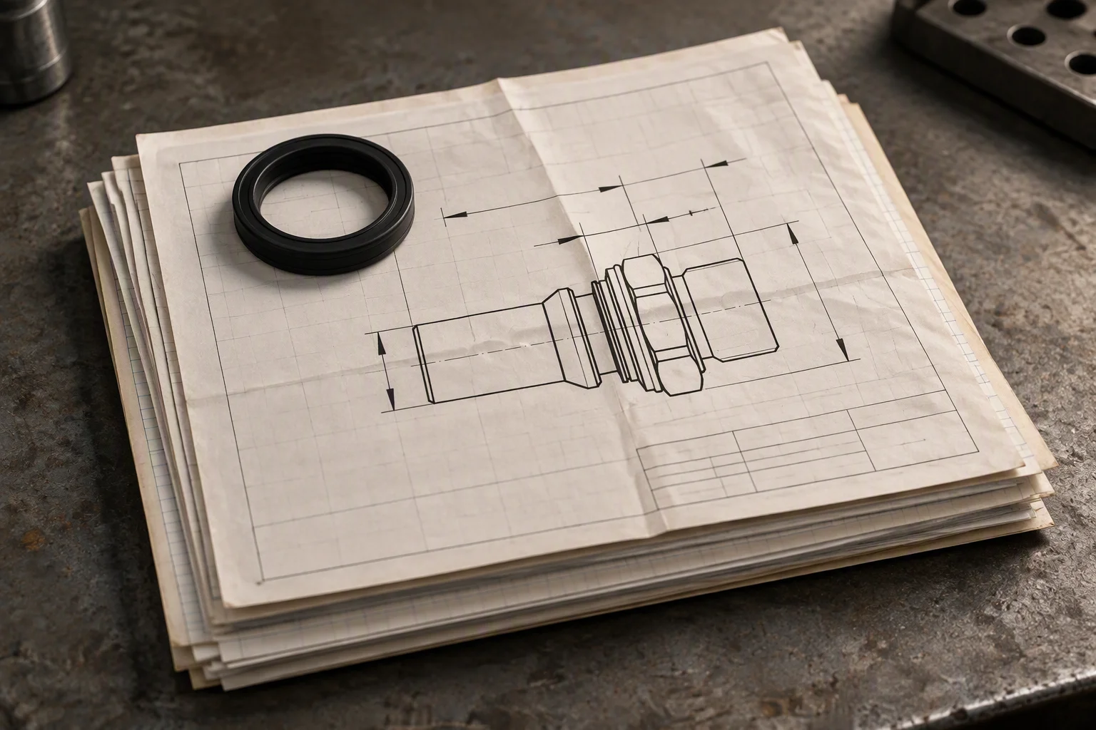
A supplier hands over the schedule, the drawing and the certificate. The loop supplies the history.
Request this note as a sheet
The eight mechanisms, the seal section drawing, the eight-figure schedule and the material certificate that goes with the metal parts.
One business day, with the file attached.
Nothing else on this sheet is promised. Price, stock and lead time are quoted against a request; the mechanisms above are the position, not a warranty on somebody else's joint.
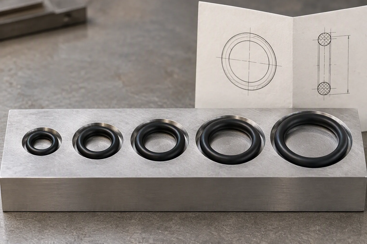
Rings are quoted by section and bore, so the drawing is what makes a request answerable.
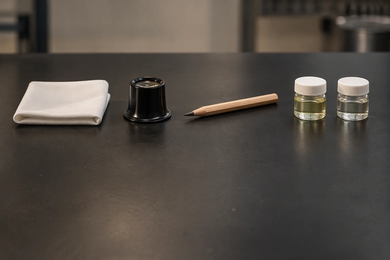
Nothing on this bench is special. The point of the note is that the bench does not need to be.
