EMS-Trade
Cooling
Loop consumables

Document ECT-01 · REV C · ISSUED 2026-09 Six lines · 48 sheets

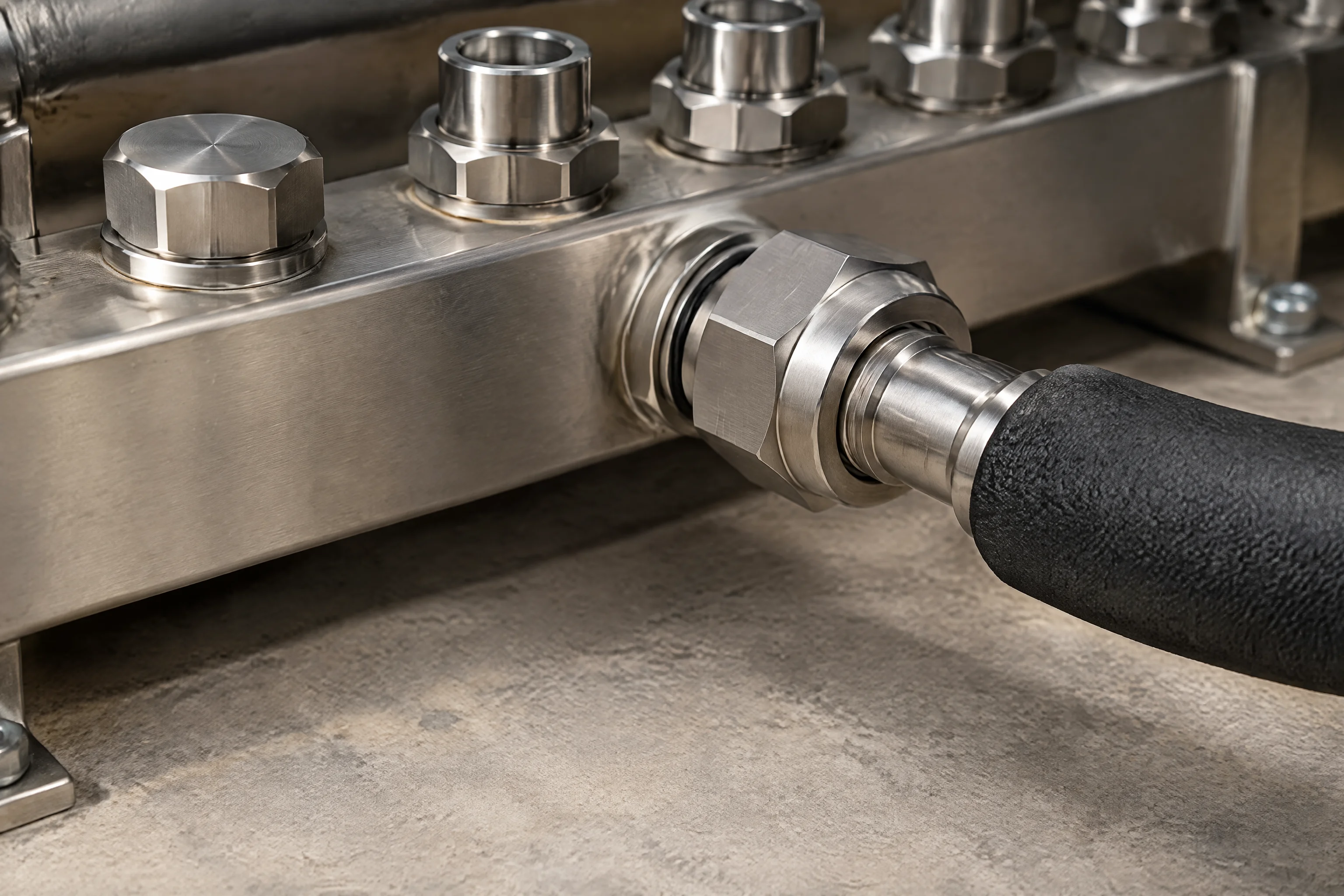
A hose tail and elbow landed on a stainless manifold port in a plant room, the hose sweeping away to the right with a row of ports behind it
Plate 03 · Fittings and seals · line 04.2 of six

Fittings and seals for the loop

Where the part sits in the run, what the interface is quoted on, and the two faces either side of it.

Metal parts EN 10204 3.1 Bodies 304 / 316L Quoted to 1.38 MPa

Request the specification file Interface table · drawings · certificates
01

Where the fitting sits in the run

Section 01 · position in the loop

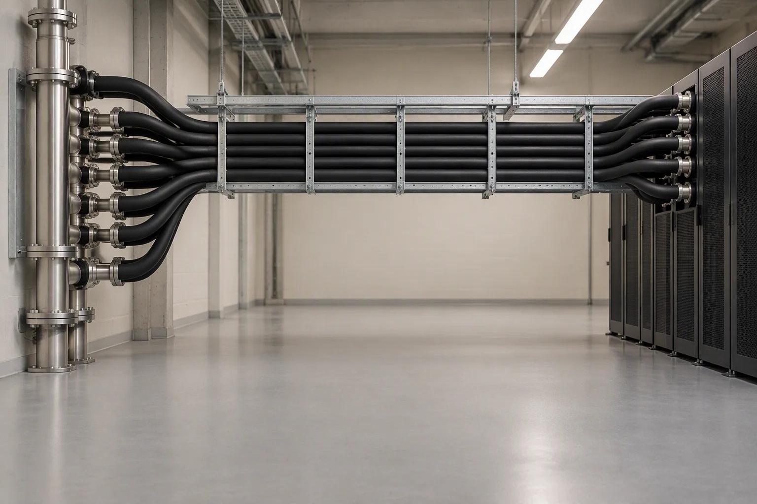
A whole hose run seen from the aisle side: the supply manifold on the left, the flexible run across the middle and the rack bulkhead on the right
Upstream · supply manifold

The part on this page sits at the two ends of that run, never in the middle of it. Upstream it lands on a manifold port; downstream it lands on the rack bulkhead.

The fitting in the run: manifold, flexible hose, fitting and rack bulkhead Coolant leaves the supply manifold, runs through the flexible hose, passes the fitting and its seal face, and arrives at the rack bulkhead. The return line runs back below. Supply manifold flexible run Fitting 01 bulkhead line Rack bulkhead Cold plate return line to the manifold Return 02

Key

  1. 01The fitting on this page: hose tail, hex and sealing face, the pressure boundary of the run.
  2. 02The same fitting on the return line, facing the other way.
FIG 01

Two fittings per run, one at each end. Everything between them is hose and clamps.
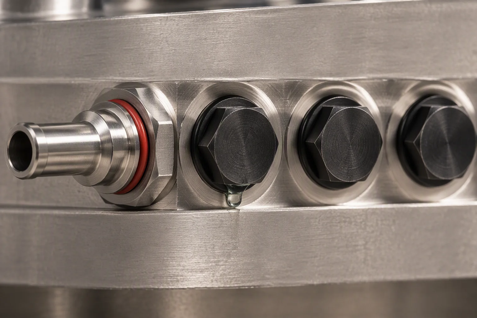
A row of unused manifold ports in close view, each with a machined flat land and a blanking plug, one port fitted with a hose tail
FIG 02

Upstream: a flat land and a thread. The land is what the ring seals on.
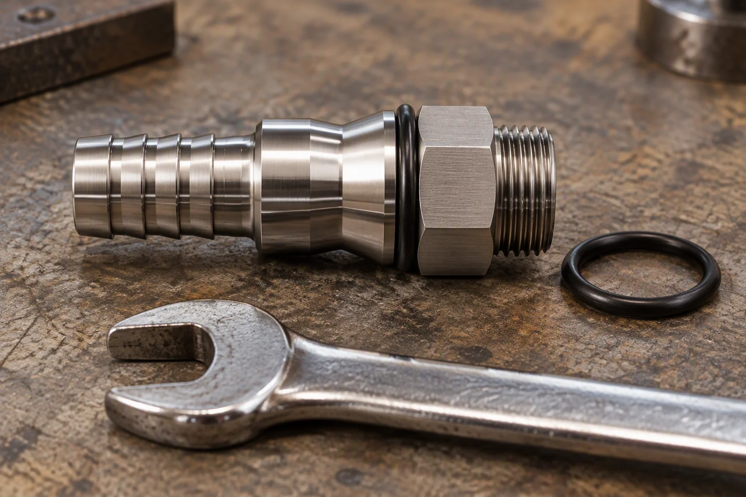
A stainless hose tail lying on a bench beside an open spanner, the hose barb at one end and the hex and thread at the other
FIG 03

The part itself: barb, hex, thread and the face in between.
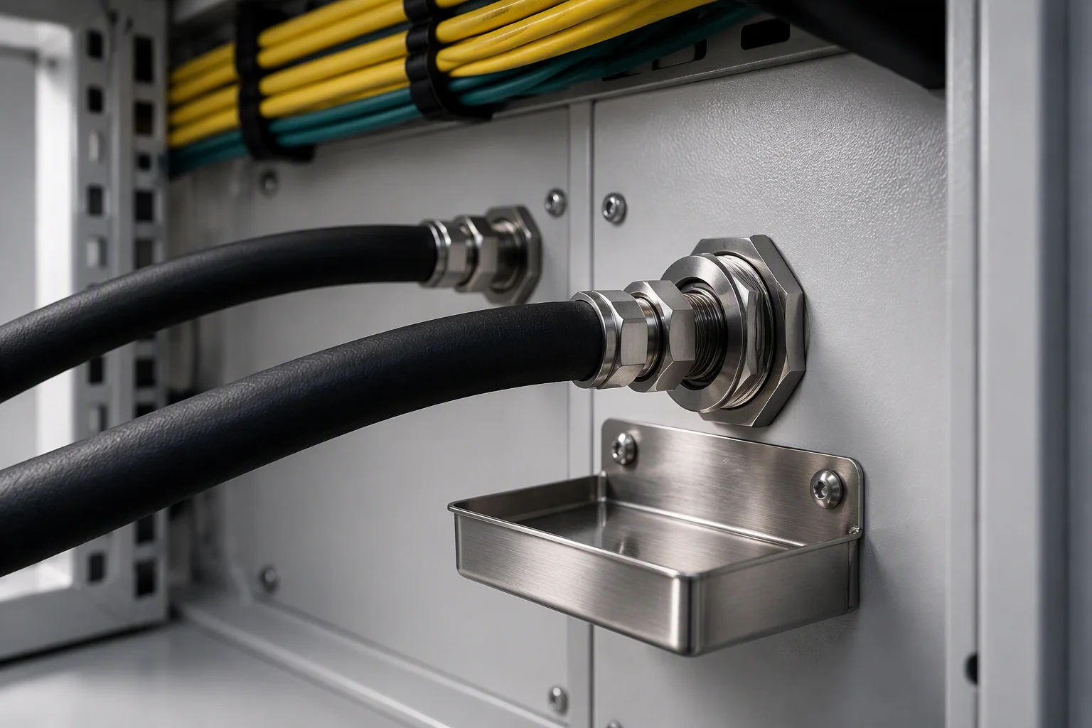
A hose arriving at a bulkhead fitting in the rear wall of an enclosure, a drip tray fixed under the joint and a second line running beside it
FIG 04

Downstream: the same interface, reached from inside the rack.

02

The interface this line is quoted on

Section 02 · interface table

Interface · what is fixed by us and what is fixed by the port
No Item Value Unit How it is quoted
01 Bore I.D 6.1 – 15.8 mm Across DASH −4 to −10, matched to the hose it serves
02 Working pressure W.P 1.38 MPa About 200 psi, DASH −4 to −6
03 Minimum burst B.P 5.5 MPa Quoted on the made-up assembly, not on the body alone
04 Coolant temperature −40 ~ +99 °C Seal material chosen against this band
05 Body material 304 / 316L , Stainless as standard, brass where the port itself is brass
06 Port thread metric, G or NPT , Cut to the port drawing on the order, never from a stock list
07 Sealing face flat land, ring in groove , The section is quoted; the outside diameter is not the number that seals
08 Make-up torque assembly drawing , Set by the port and the seal, so it travels with the drawing, not with this sheet
09 Material certificate EN 10204 3.1 , Per heat, on the metal parts
10 Cleanliness target ISO 4406 17/15/12 , The loop figure the run is commissioned to
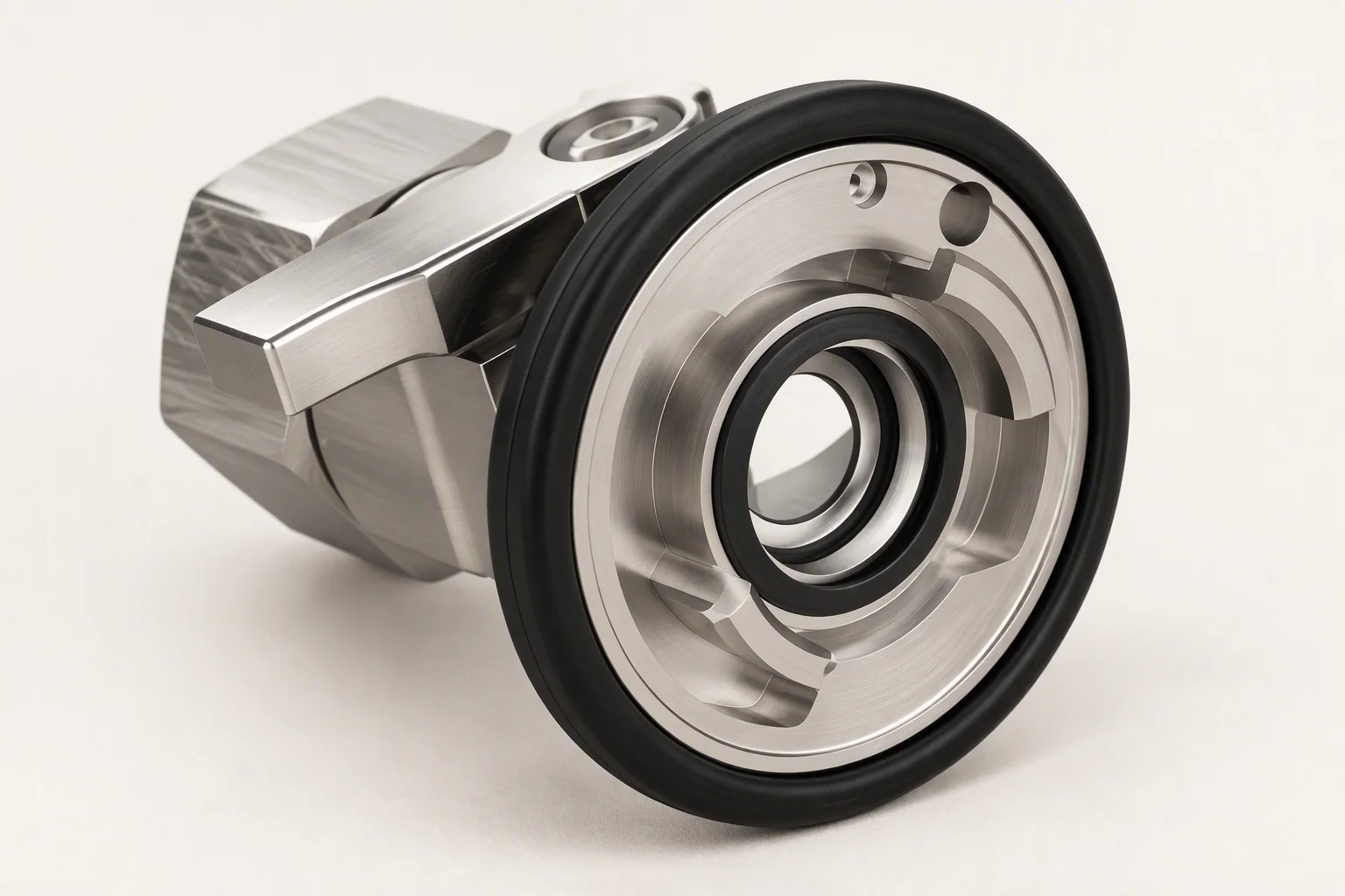
A stainless coupling body photographed on a white ground: knurled nut at the front, black O-ring seated in the face behind it and a machined spigot at the back
PL 01

A body with its ring in place. The knurl is what a hand turns, not what seals.
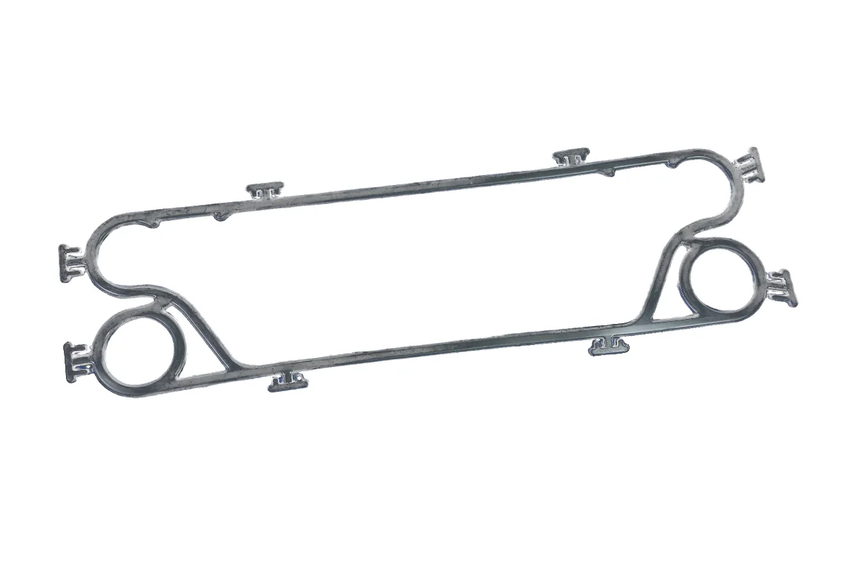
A black elastomer profile gasket photographed on a white ground: a long loop with a moulded lip along it and two locating tabs at each end
PL 02

A profile seal, not an O-ring. The lip does the work and the tabs hold it in place.

03

The two parts either side of it

Section 03 · mating dimensions

Against the hose
the barb takes the bore, so the tail is cut to the same DASH −4 to −10 grade as the hose
Against the port
thread and land come off the port drawing; a land that is too narrow leaves the ring unsupported
Against the clip
the clip sits behind the barb, over the 1 – 2 braid layers, never on the braid end
Against the bend
the fitting adds its own length to the run, which eats into the 24.5 – 69 mm bend radius
Against the age
a ring that has been compressed for years does not come back, so a re-made joint gets a new ring
Lead time for a made-up end
samples 7–10 days, production 25–35 days
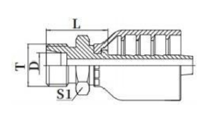
Section drawing of a hose tail assembly: length L along the body, the sealing diameter D, the hex across flats S1 and the thread T marked at the port end
DR 01

The drawing the tail is cut to. Length L, diameter D, hex S1, thread T.
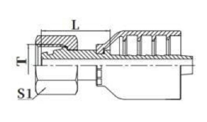
Section drawing of a straight adapter: length L, thread T and the sealing land S1 shown where the ring is compressed against the port face
DR 02

The same interface on a straight adapter, where S1 is the land the ring sits on.

04

Seals as they arrive

Section 04 · specimen strip

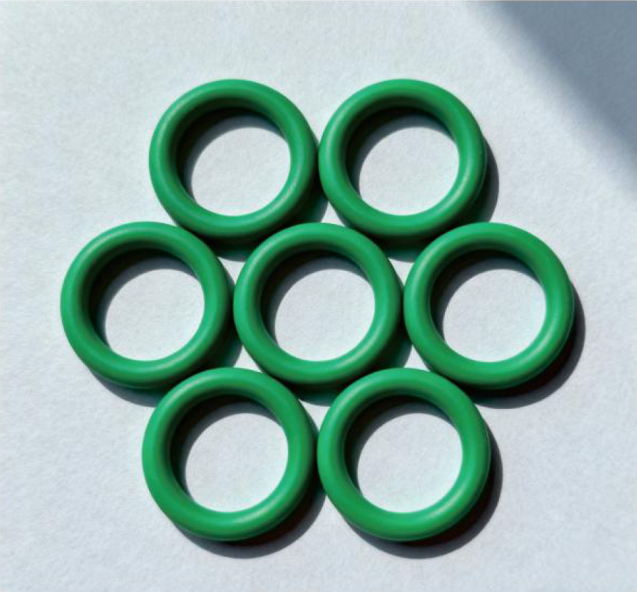
Seven green O-ring seals laid out in a row on a grey ground, graded by size from left to right
PL 03

Graded by size. The ring is bagged against the fitting it was cut for.
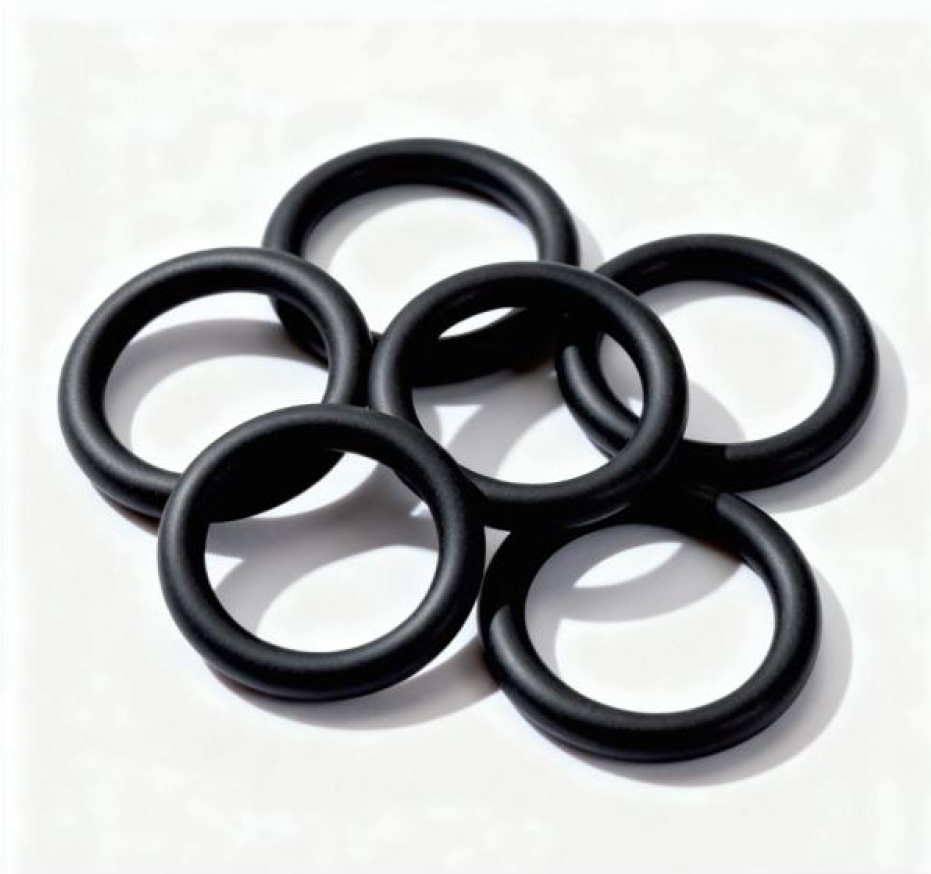
A group of black O-ring seals arranged on a white ground in a shallow bowl of sizes, the moulding flash visible on the smallest
PL 04

Black EPDM rings, the same elastomer as the hose tube.
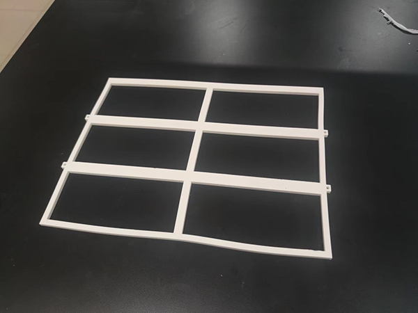
A white silicone gasket frame with six rectangular windows, laid flat on a dark bench with one moulded tab standing proud of the frame
PL 05

A frame gasket, die cut to a housing rather than turned on a lathe.

05

What ships with the fittings

Section 05 · documents

Material certificate
EN 10204 3.1 per heat, on the bodies and the tails
Seal material
elastomer grade named on the sheet, matched to the coolant band of −40 ~ +99 °C
Drawings
outline and section drawings for each end, dimensioned as above
Tests
hydrostatic on the made-up assembly, to the 5.5 MPa minimum
Packing
rings bagged by size, fittings capped, export crate to ISPM 15
Standards held
ISO 9001 quality system, CE and RoHS on the delivered parts, REACH on the elastomer
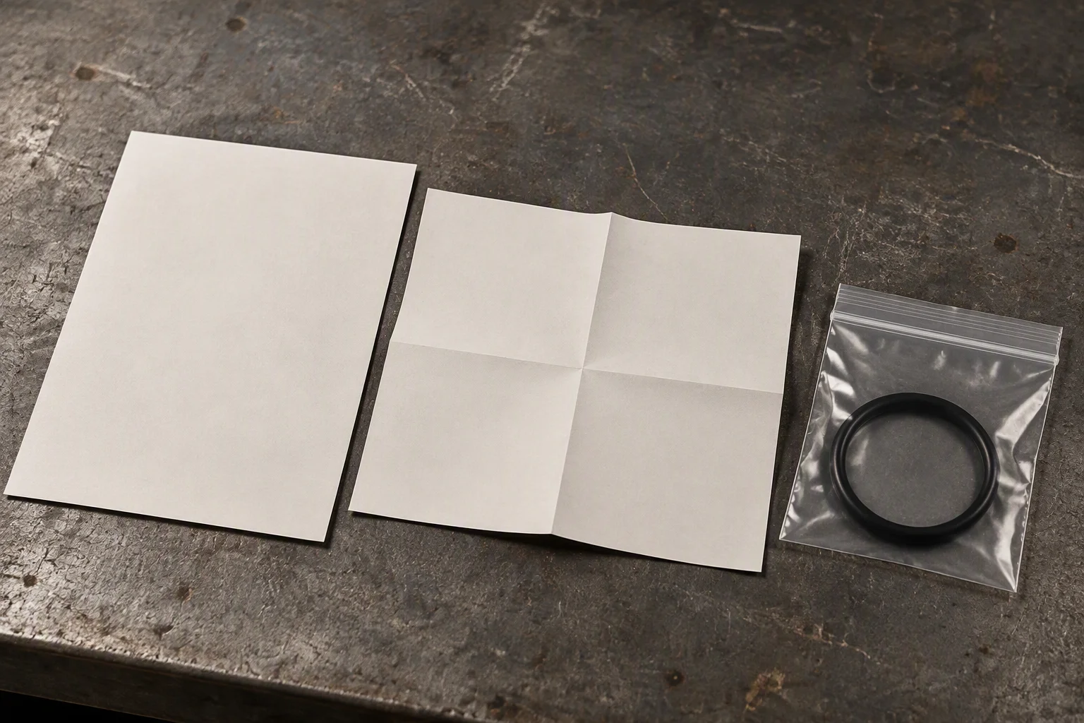
A material certificate sheet and a folded section drawing on a bench beside a bagged O-ring, all blank of print and unmarked
FIG 05

The certificate and the drawing travel in the same packet as the parts.
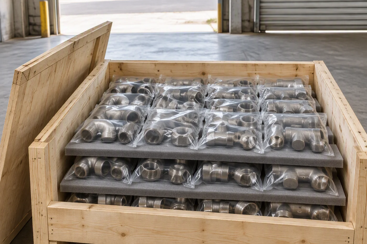
An export crate on a loading bay with the lid off, sealed bags of fittings packed in rows inside and foam between the layers
FIG 06

Packed to the crate, not to the pallet. Bags keep the sealing faces off each other.

Read next · Hose & piping · EPDM hose · Seal degradation mechanisms

DOCUMENT REQUEST

Request the specification file

The interface table, the drawings, the certificate and the test report for the parts you are choosing between.

If the form cannot send, this address takes the request instead: sales@ems-cool.com
The only promise on this page

One business day, with the file attached.

Nothing else on this sheet is promised. Price, stock and lead time are quoted against a request.
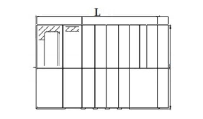
Section drawing of a fitting body: length L and diameter D dimensioned across a stepped bore with moulded ridges along the outside
DR 03

A body drawing, dimensioned L and D. Every end on an order is issued like this.
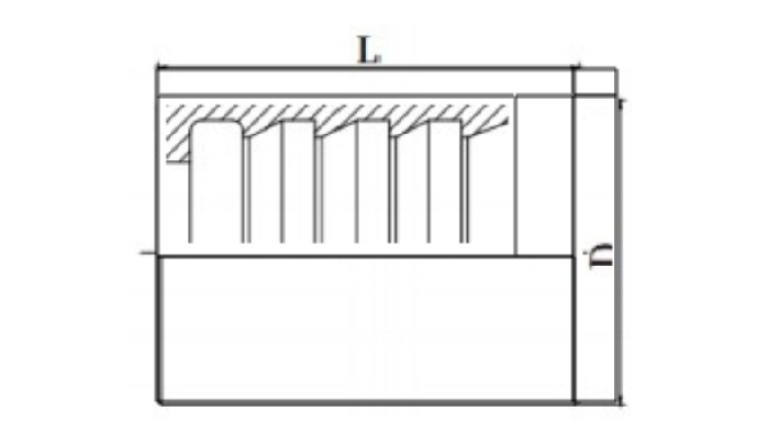
Section drawing of a sleeve fitting: length L and diameter D across a ribbed outer profile and a plain bore
DR 04

The sleeve that goes over the same interface, drawn the same way.