EMS-Trade
Cooling
Loop consumables

Document ECT-01 · REV C · ISSUED 2026-09 Six lines · 48 sheets

Plate 04 · Quick disconnects · line 04.3 of six

Quick disconnects for the loop

One coupling per grade, dry on both halves.
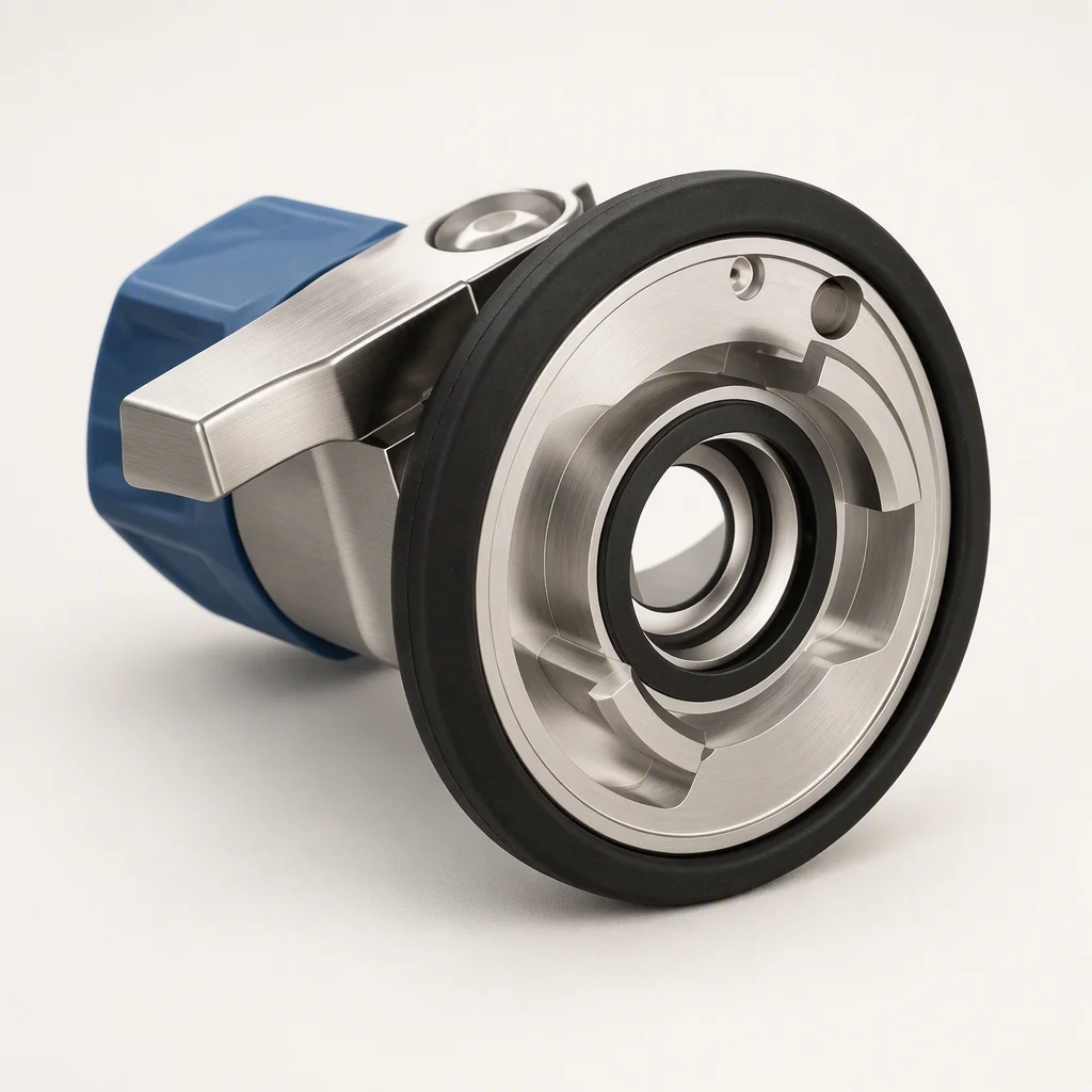
Type UQD Working pressure 1.38 MPa Bore 6.1 – 15.8 mm

Request the specification file Grade matrix · drawings · packing spec
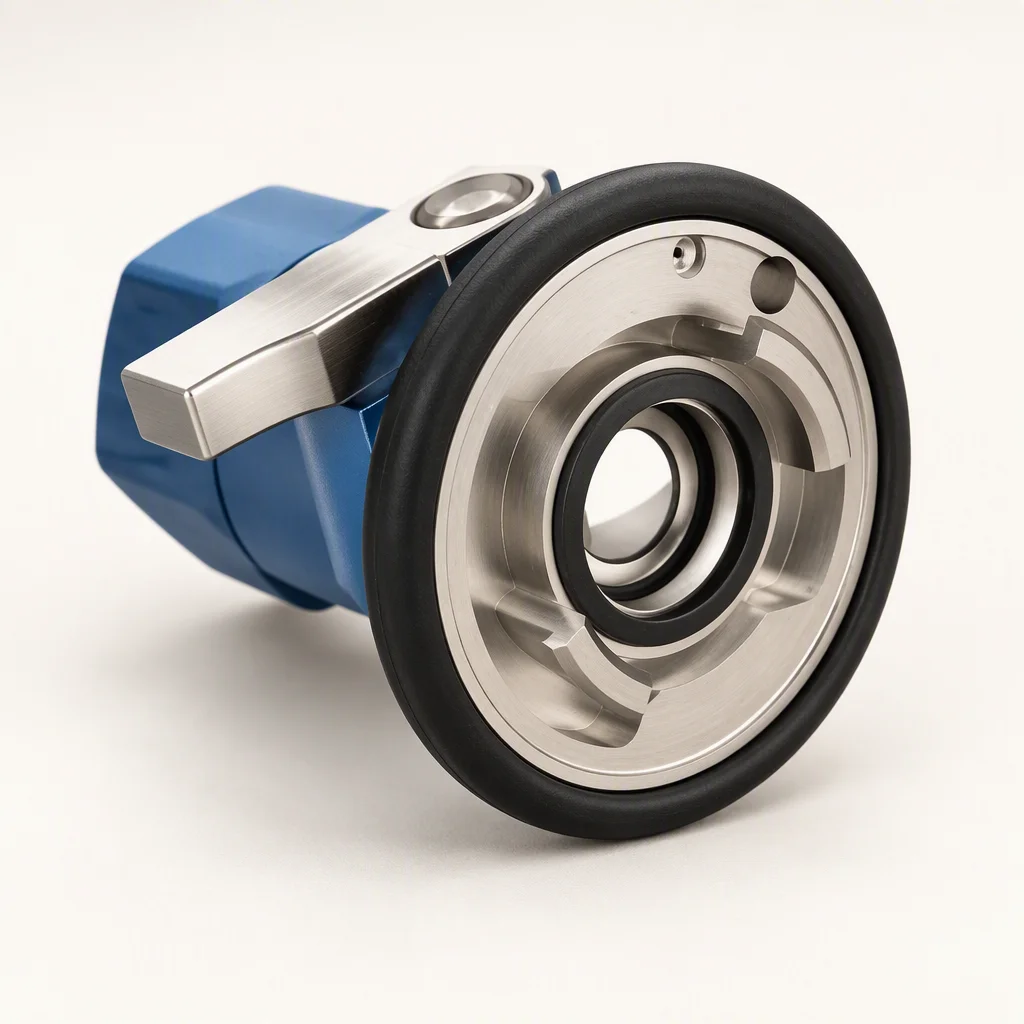
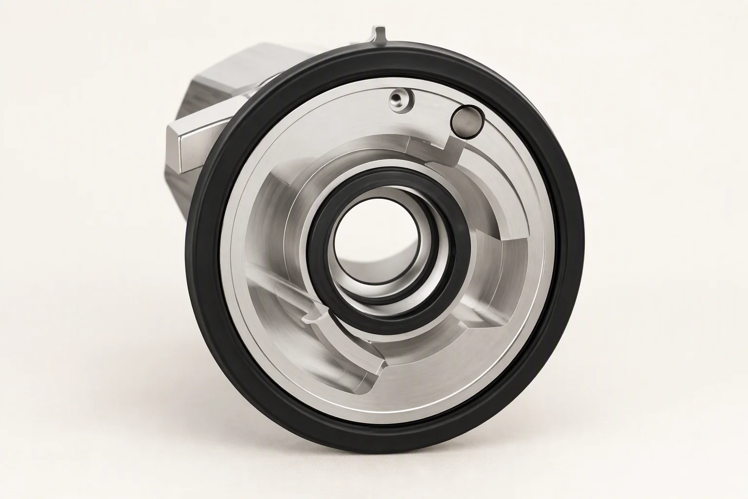
A stainless quick disconnect coupling half standing on a white ground, the sleeve and the open seal face towards the camera
The matching plug half of a quick disconnect on a white ground, its nose and O-ring facing the camera
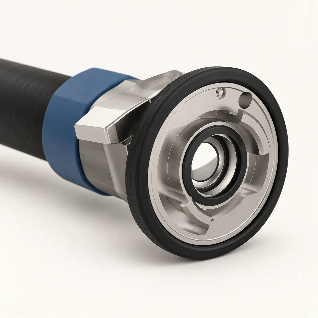
A coupling half made up on the end of a black EPDM hose, the hose tail and the hex visible behind the sleeve
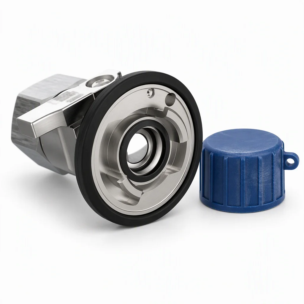
A blue plastic dust cap lying beside an open coupling half on a white ground, the cap ribbed and slightly scuffed
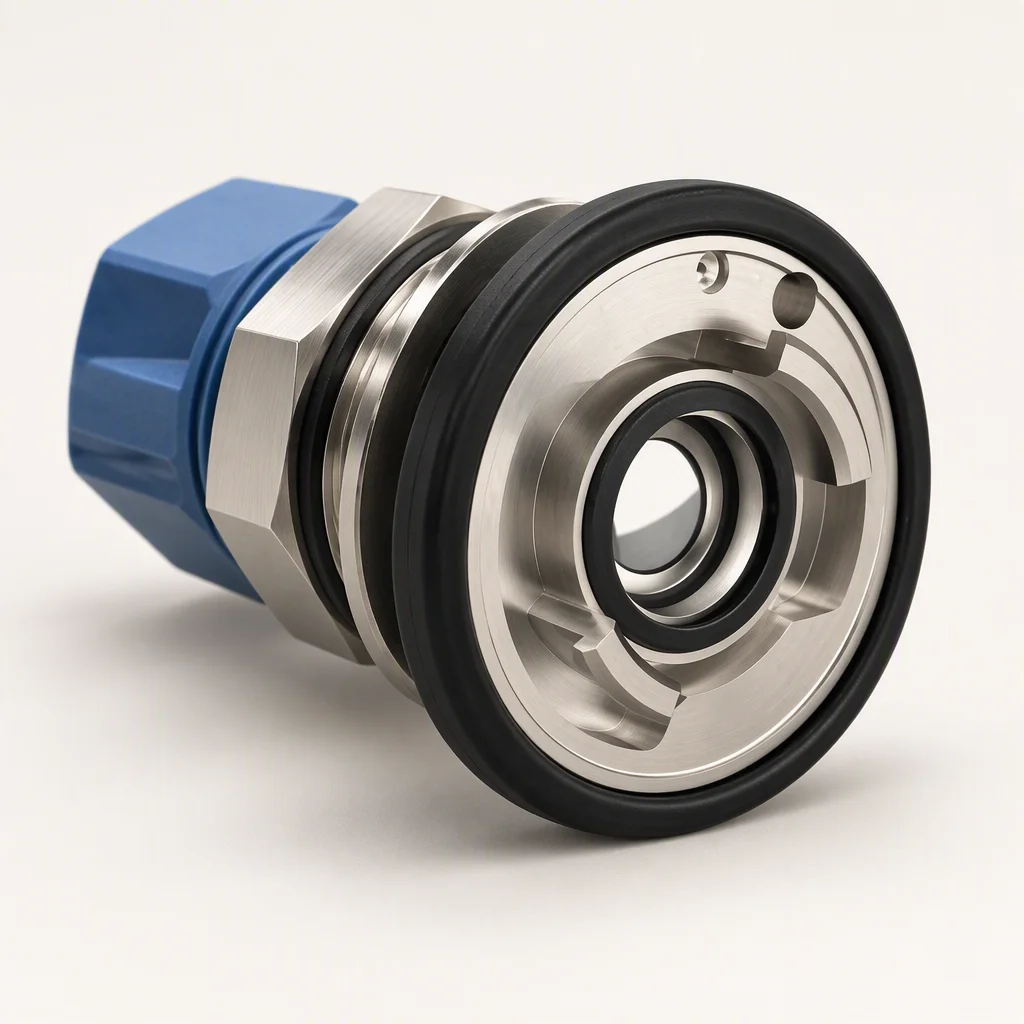
A bulkhead mount coupling on a white ground, its panel nut and washer in place behind the body
01

Which grades can be quoted

Section 01 · matrix by grade

Quick disconnects · five grade marks, and what is quoted on each
Item DASH −4 · −5 · −6 DASH −8 DASH −10
Bore I.D 6.1 – 15.8 mm across the five marks
Working pressure W.P 1.38 MPa, about 200 psi open on this sheet open on this sheet
Minimum burst B.P 5.5 MPa, on the made-up assembly
Coupling type UQD, one size per grade, dry break on both halves
Open cycles service life not quoted here
On break both halves close, so the run stays wet and only the joint drains

Two cells are deliberately not filled. Working pressure on DASH −8 and −10 is quoted per grade on the data sheet, and open cycles is a figure that depends on the coolant, the alignment and the hand on the sleeve. Anyone who prints one number for it is printing an average.

What this sheet will say instead: the seal face is the part that wears, it is replaceable on both halves, and the sleeve travel before the halves separate is on the outline drawing.

A coupling pair separated at the rear of a rack, one half still mounted on the bulkhead and the other on a hose hanging free
FIG 01

Rack swap. The halves part in one movement and both of them close.
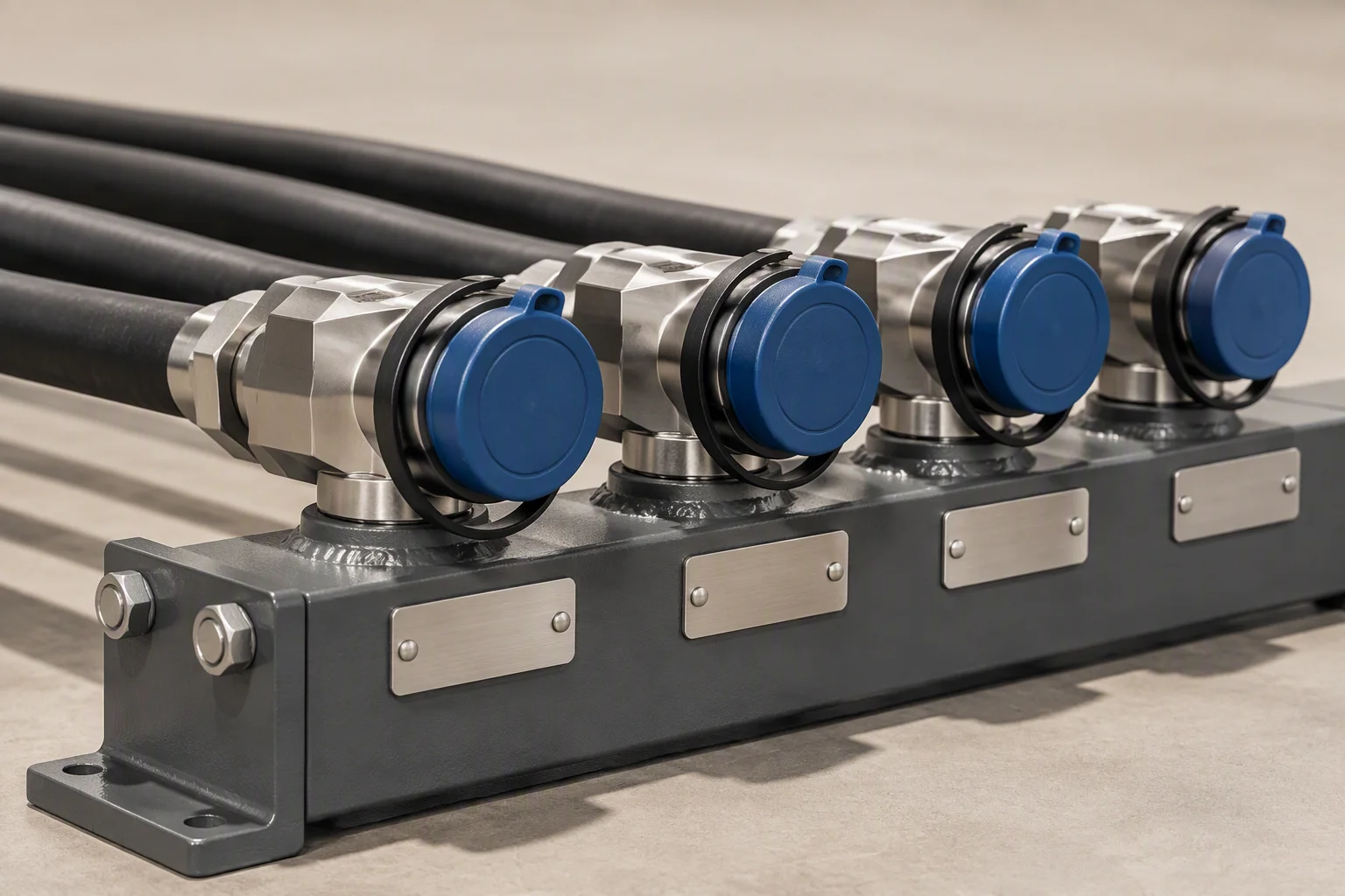
Coupling halves in a row on a manifold, each one capped against dust, with the hose runs leaving them in parallel
FIG 02

Manifold row. Capped when it is spare, so the face is clean when it is needed.
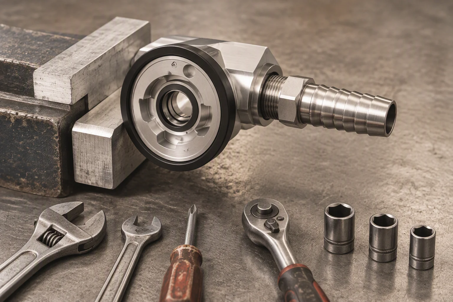
A coupling half held in a vice on a bench with a hose tail being made up into the back of it, tools laid out alongside
FIG 03

Bench end. Every half is made up and pressure tested before it is packed.

02

The parts, as they are issued

Section 02 · specimen strip

A stainless coupling body on a white ground: knurled nut at the front, black O-ring seated in the face behind it and a machined spigot at the back
PL 01

The face, the ring and the knurl. Only one of the three is a wearing part.
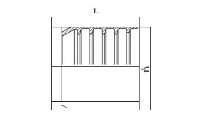
Section drawing of a coupling sleeve: overall length L across the ribbed body and the diameter D marked at the open end
DR 01

The sleeve in section. Length L and diameter D on the drawing the part is cut to.
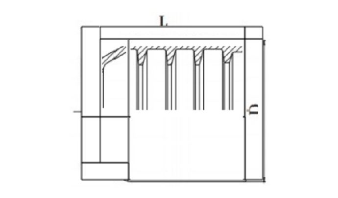
Section drawing of a coupling body: length L, outer diameter D and the internal bore profile drawn with a machined inner step
DR 02

The body. The inner step is the seat the ring closes against.

03

Minimum order and lead time

Section 03 · order terms

Minimum order
1 carton on standard grades; 500 m on custom lengths
Samples
7–10 days, with the first article record
Production
25–35 days; 15 days on a rush order, agreed in writing
Trade terms
FOB Shenzhen, CIF or DDP on request
Payment
T/T 30% with the order and 70% against the bill of lading copy; letter of credit at sight on large orders
Documents
invoice, packing list, bill of lading, certificate of origin, EN 10204 3.1 material certificates, test report
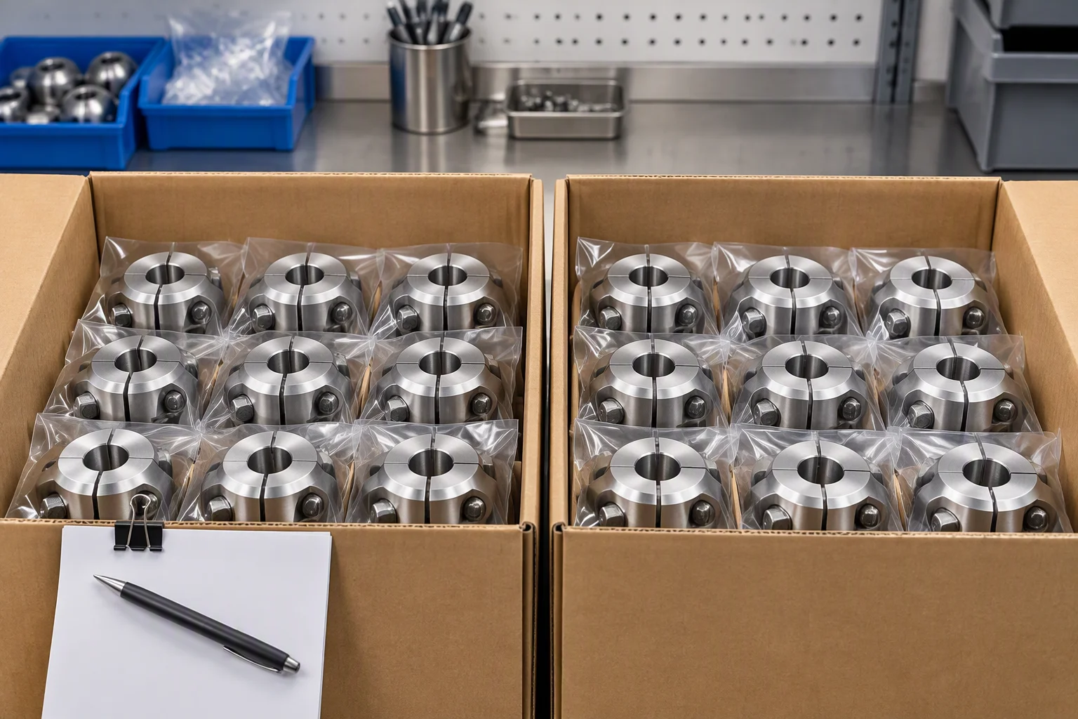
Open cartons on a bench with coupling halves in rows inside, each one bagged, and a tally sheet clipped to the box edge
FIG 04

Counted into the carton, not weighed into it. One carton is the minimum.
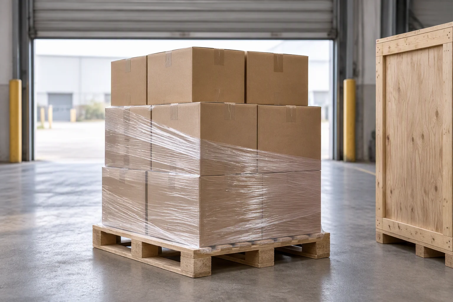
Cartons stacked on a pallet on a loading bay with stretch film half applied and a crate beside them
FIG 05

Consolidated onto the pallet with the rest of the run.

04

How the order is packed

Section 04 · packing and papers

Packing · one line per item type
Item Unit Inner packing Outer packing Marking
Coupling halves 1 pc bagged, capped both ends carton, foam between rows batch and grade on the label
Seals and rings 1 bag bagged by size, air excluded carton, flat size on the bag
Hose, custom length 500 m coiled on a wooden reel crate to ISPM 15 reel label, batch and length
Papers 1 set in a pouch in carton 1 , certificate, test report, drawing
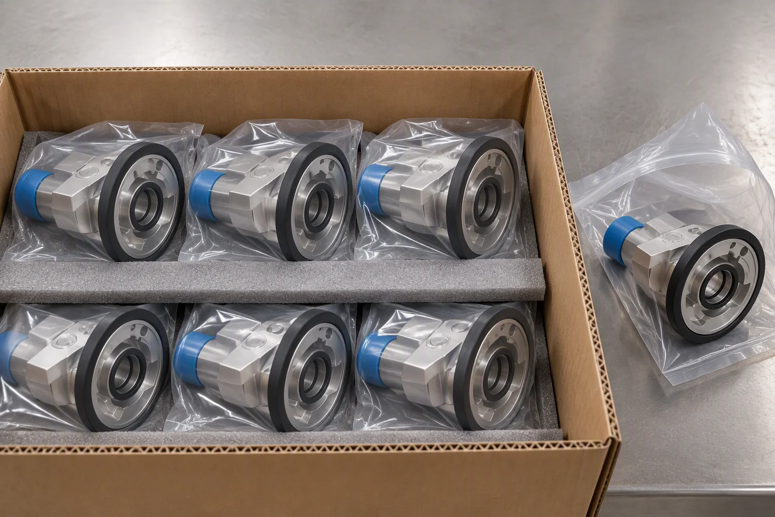
Sealed bags of coupling halves laid flat in a carton with foam sheet between the layers, one bag open beside them
FIG 06

Bags and foam. Nothing metal touches a seal face in transit.
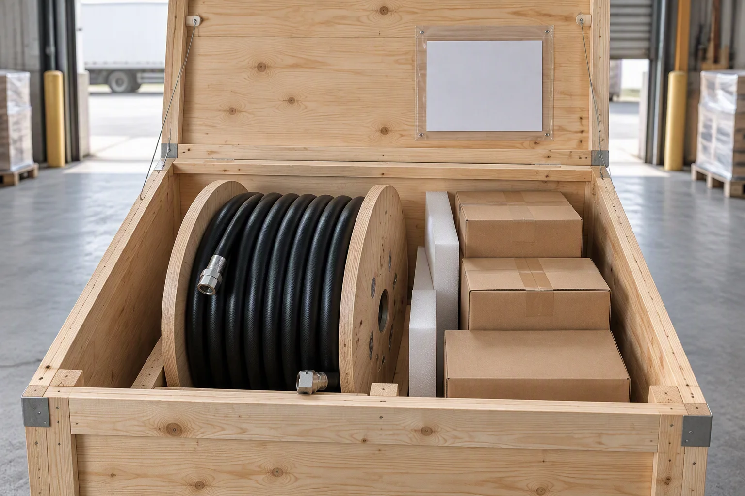
A wooden export crate with the lid open on a loading bay, a reel of hose standing inside and fittings cartons packed beside it
FIG 07

A crate to ISPM 15 on the outside, and the packing list on the inside of the lid.

05

Where the order actually comes from

Section 05 · supply network

7–10 days Samples The sample end is cut, made up and first article inspected on a partner line before it is sent.
25–35 days Production The run is braided, cut and terminated on the same lines the sample came off, then pressure tested.
FOB Shenzhen Consolidation Inspected, packed and consolidated in Shenzhen, with the export documents in English.

This line does not run its own hose plant. The braiding, the machining and the elastomer moulding happen on partner lines, and what is ours is the specification, the inspection and the packing.

That is the reason the four documents are the product here. A part from a partner line is only as traceable as the paperwork that arrives with it, and the paperwork is checked on every batch.
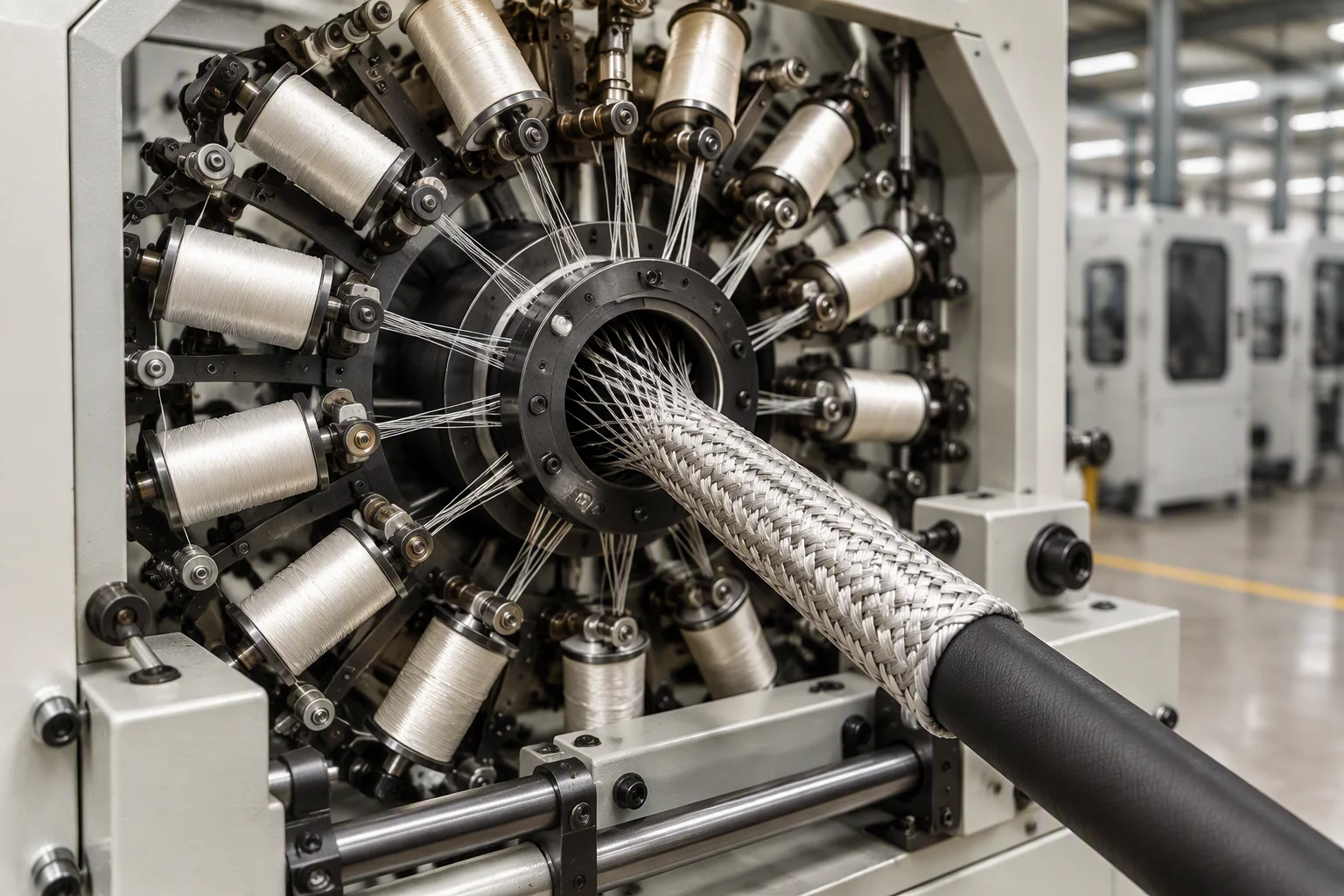
A braiding machine on a partner line with bobbins of fibre wound on the carriers and hose passing through the centre
FIG 08

Stage 01. Braid over the tube, on the line the sample came off.
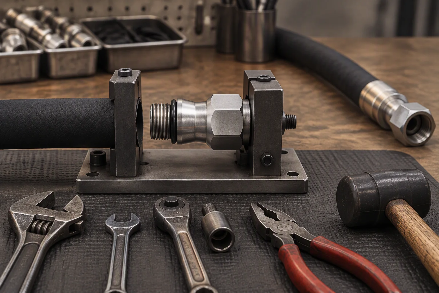
An assembly bench with a cut hose and a fitting half made up in a fixture, hand tools laid out in order beside them
FIG 09

Stage 02. Made up to the drawing, then tested.
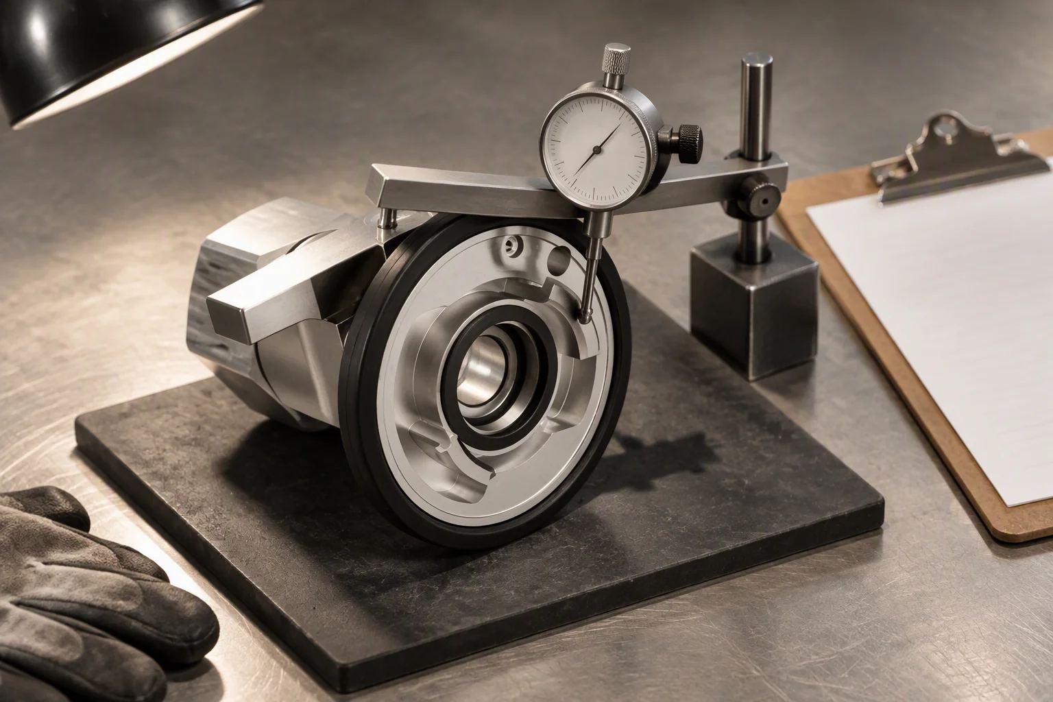
A pad on an inspection bench with a coupling half laid on it, a gauge across the seal face and a record sheet beside it
FIG 10

Stage 03. Gauged and recorded, batch by batch, before it is packed.

Read next · Hose & piping · Supply network · Quick disconnect duty cycles

DOCUMENT REQUEST

Request the specification file

The grade matrix, the drawings, the packing spec and the terms. Tick what you need.

If the form cannot send, this address takes the request instead: sales@ems-cool.com
The only promise on this page

One business day, with the file attached.

Nothing else on this sheet is promised. Price, stock and lead time are quoted against a request.
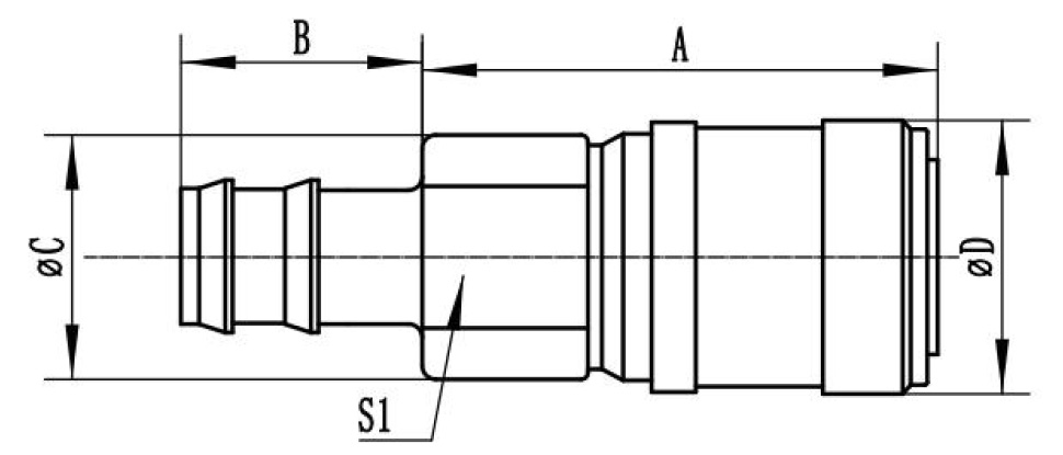
Outline drawing of a hose assembly: overall length A, tail length B, and diameters C and D marked across the couplings at each end, with the seal land S1 called out
DR 03

Assembly outline. Length A end to end, and the coupling diameter each end.
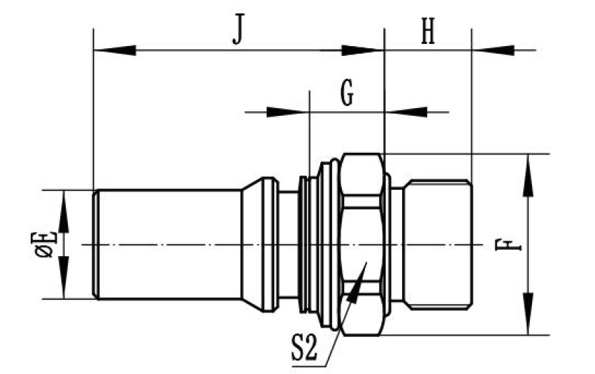
Section drawing of a coupling end: length J along the body, H across the hex, G at the seal land and F at the thread, with the sealing face marked S2
DR 04

The end in section. S2 is the face the ring closes on.
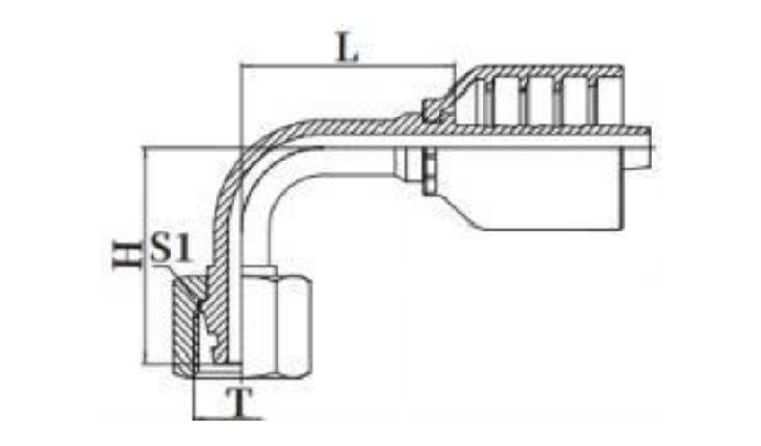
Section drawing of a right angle coupling end: length L along the elbow, thread T at the port and the seal land S1 with H across the nut
DR 05

The right angle version, drawn to the same convention.