
Grease and phase change material for the loop
Two classes that both start as a solid on the bench: one is printed into the joint, the other is laid in as a sheet and settles once the joint warms through its window.
One business day, with the file attached
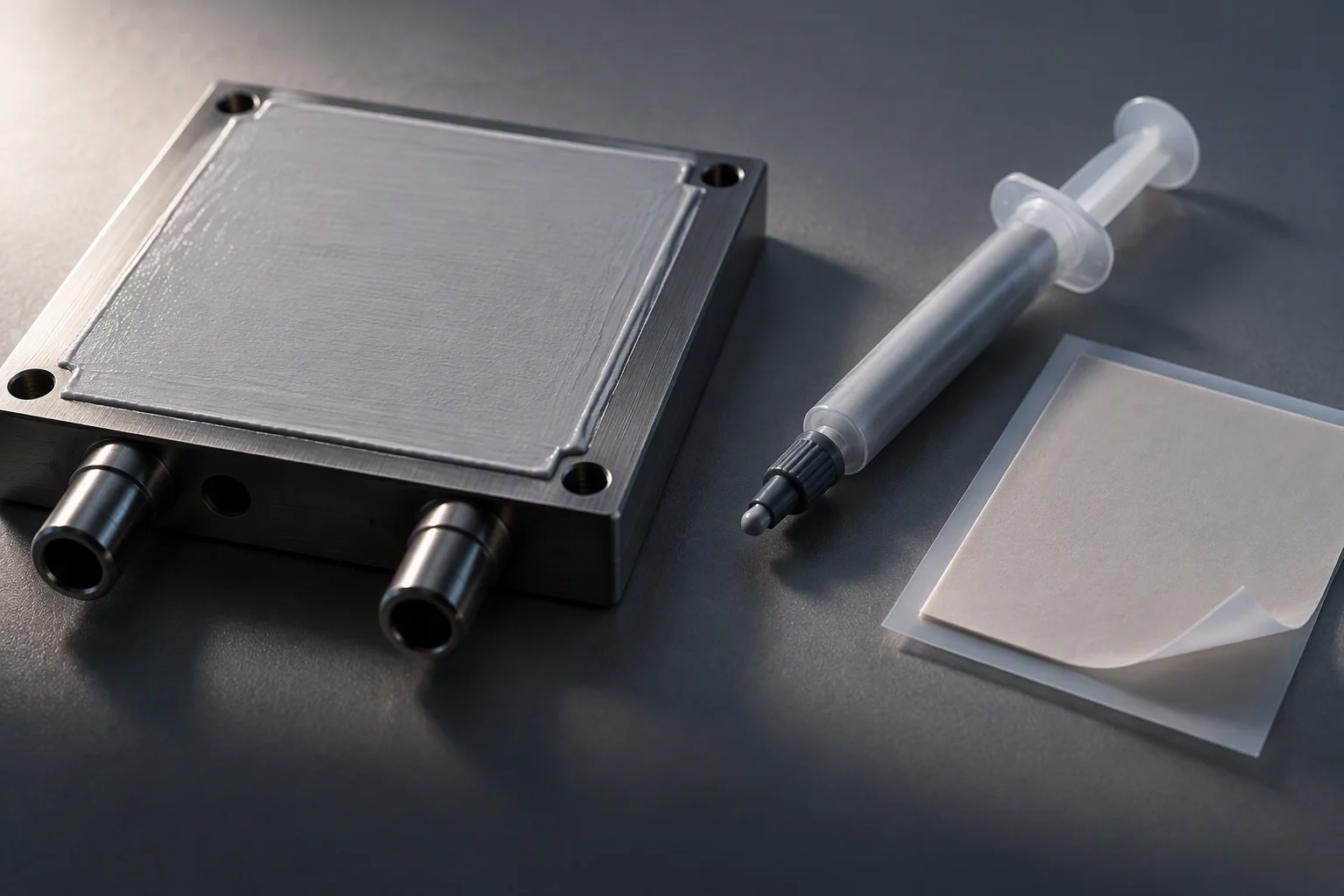
The two classes side by side: one is printed, one is laid in as a sheet.
What the interface is, in section
Key
- 01The receiving face. Its flatness and finish decide how much material has to be there at all.
- 02The interface layer. Thickness here is the bond line, and it is the number the quotation does not carry.
- 03The second face, machined with tool marks. Bridged, not mated.
- 04Closure. Set by the fasteners and the metal stops, not by the interface material.
Left: as assembled. Right: after the joint has warmed through the phase window.
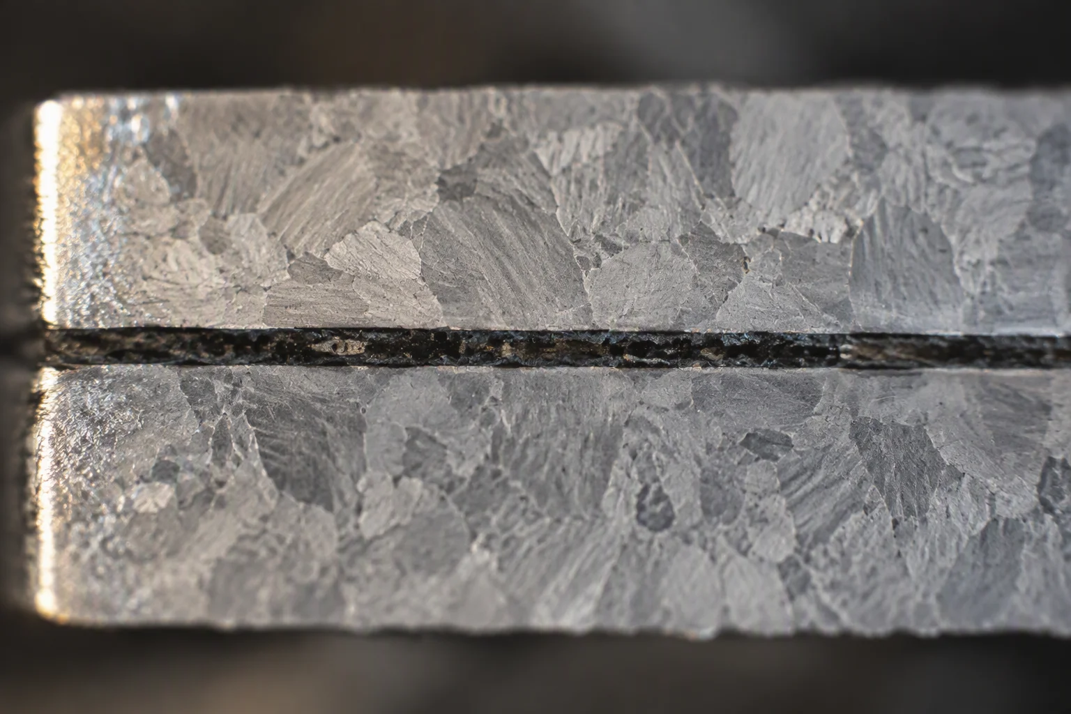
Cut through a clamped joint and lapped: the layer is a line, not a film.
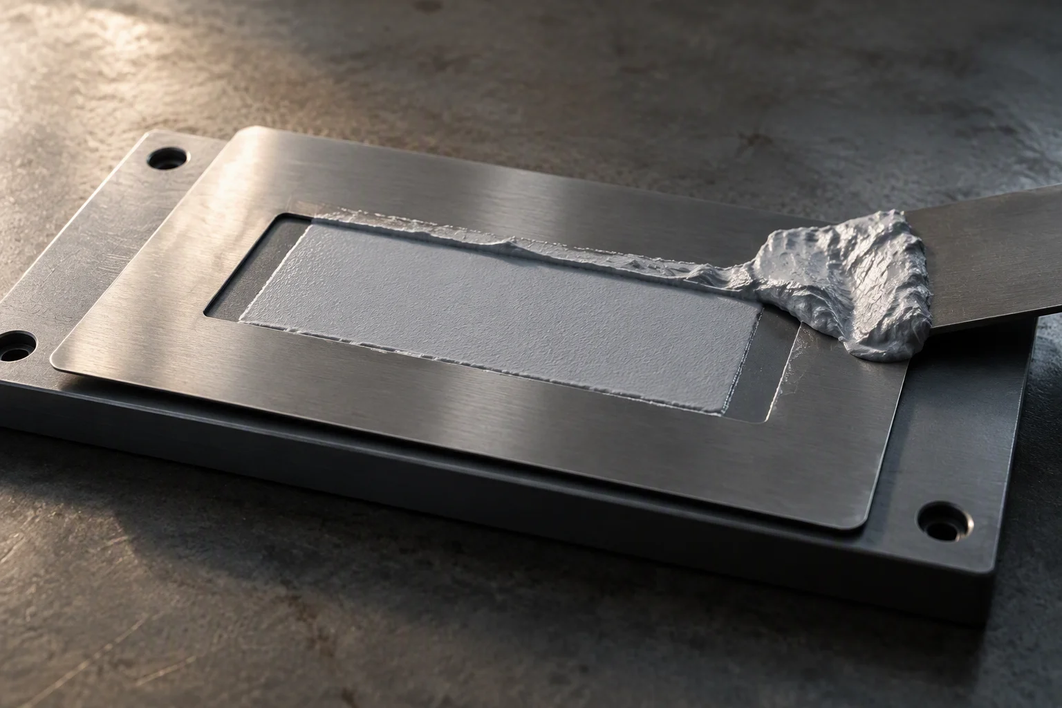
Printed through a stencil to the footprint, so the layer is set before the joint closes.
Read next · Thermal materials · Graphite sheet
The layers in the order they are stacked
| Layer | What it is | Material | What it has to do |
|---|---|---|---|
| 01 | Heat source face | machined spreader | Carries the load and the flatness the interface is measured against |
| 02 | Interface, printed | thermal grease | 1.0–6.0 W/m·K; lowest bond line of the four, and the one that pumps out |
| 03 | Interface, laid in | phase change sheet | 2.0–8.5 W/m·K; solid on the bench, wet once the window is reached |
| 04 | Cold plate face | machined tool face | Clipped by the fasteners; the closure it gives is the bond line you get |
| 05 | Retention | moulded frame | Holds the interface where the drawing put it when the joint is opened |
A layer list is read from the heat source outwards, because that is the direction the heat travels and the direction the stack is built in.
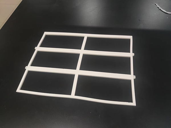
The sequence, and where each step is checked
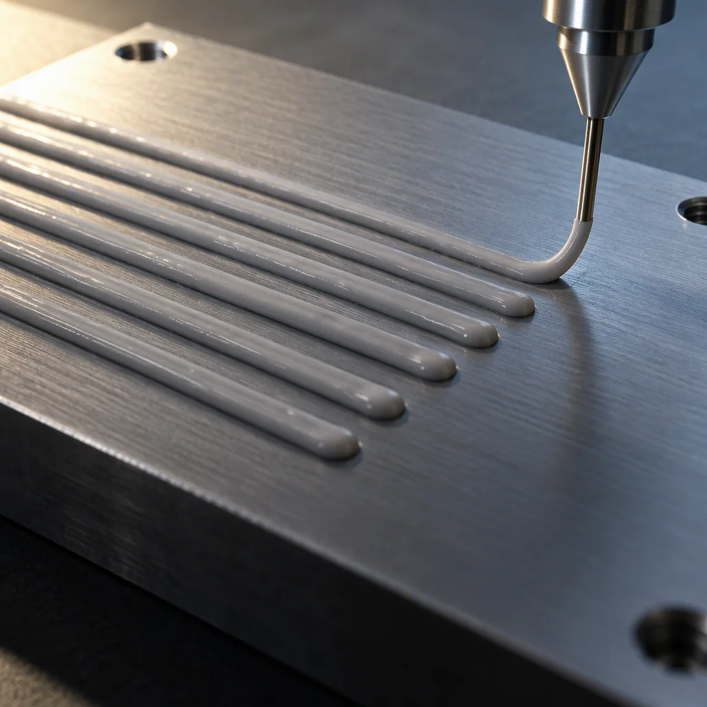
Drawn in even lines where a stencil is not practical.
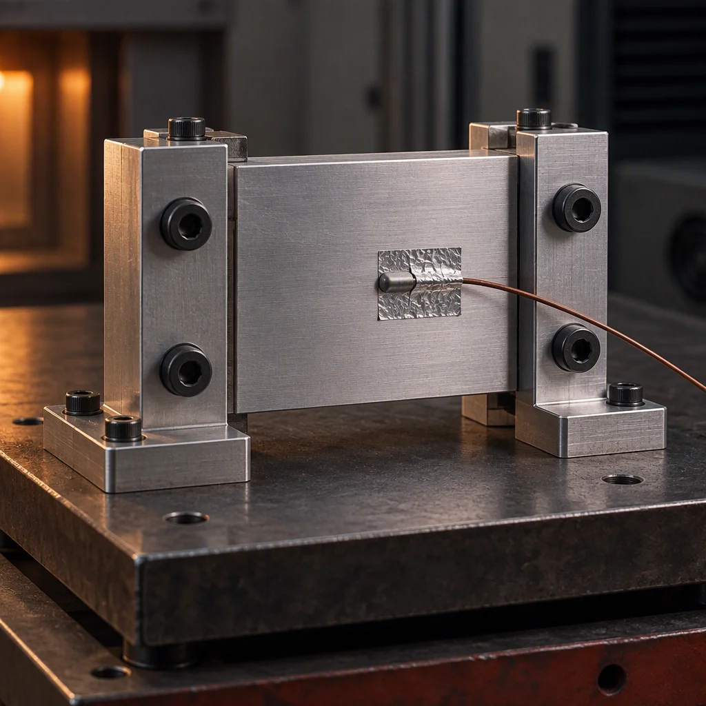
Cycled with a probe on the face, so the window is measured and not assumed.
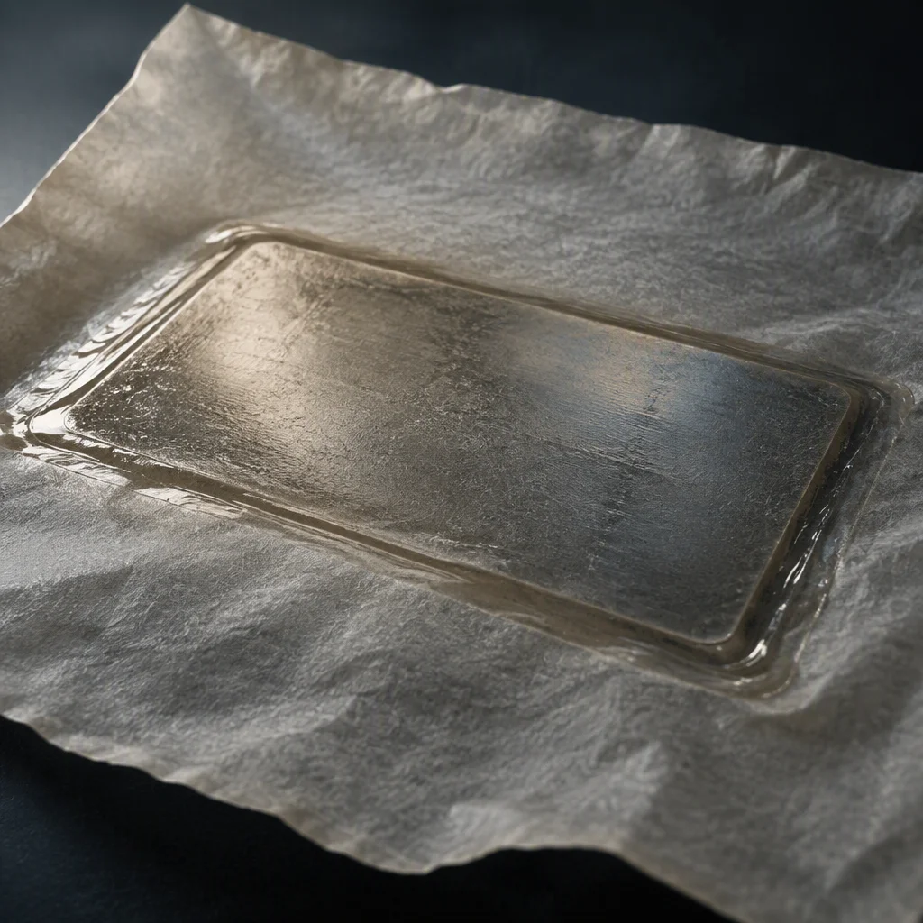
Pulled warm: the sheet has settled to the outline it was cut to.
Thermal grease
1.0–6.0 W/m·KThe lowest interface thickness of the four classes, printed to the footprint and held there by the closure. It is also the class that moves: heat cycling walks the material out of the bond line, and a pumped-out joint conducts through the ring it left outside.
Phase change material
2.0–8.5 W/m·KA sheet on the bench and an interface in service. Below its window it behaves like a pad, which is what makes it forgiving to fit; once the joint warms through the window the interface settles and stops being the part that moves. The trade is the window itself: it has to be reached.
The face the material lands on
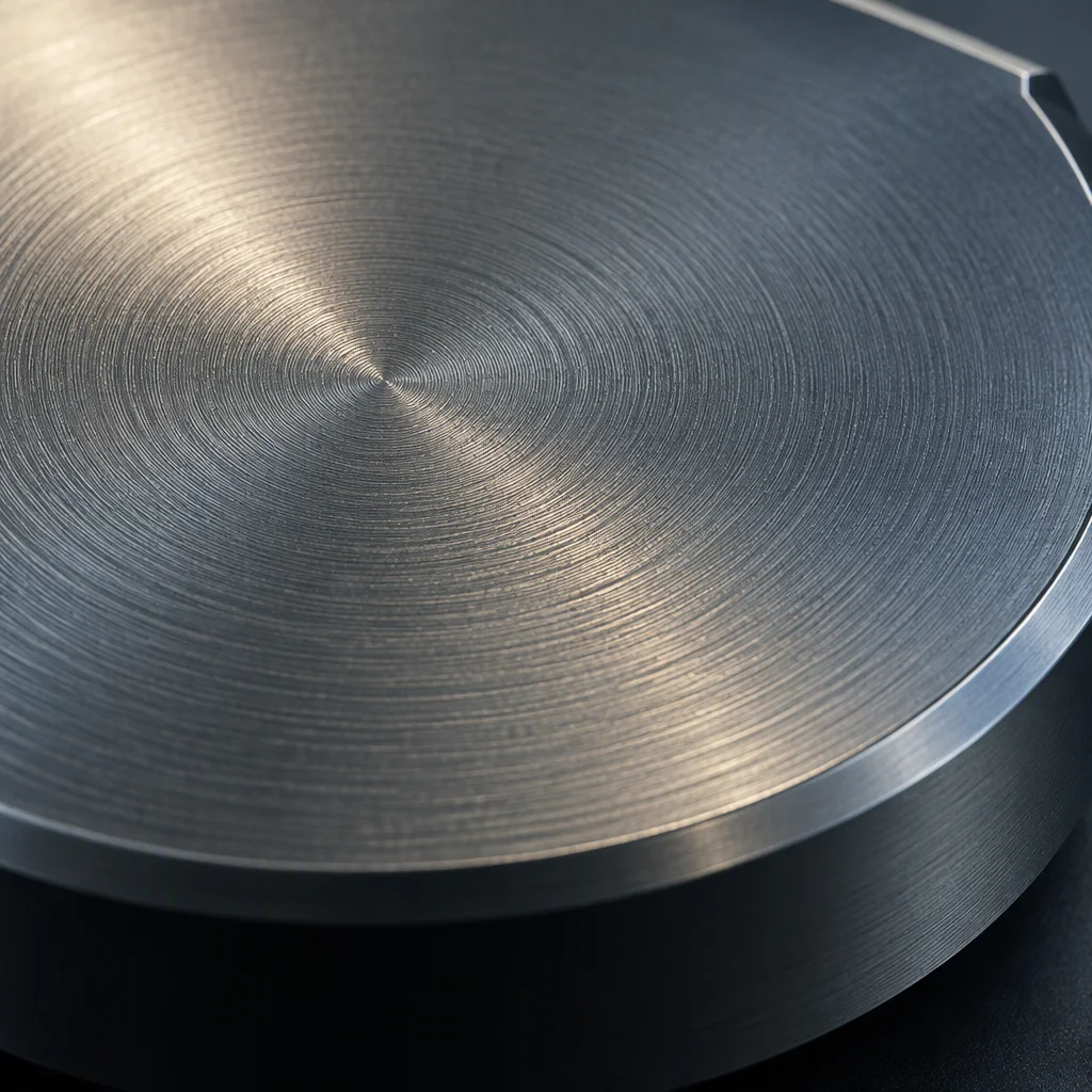
Milling marks: ridges the interface has to fill before it can conduct.
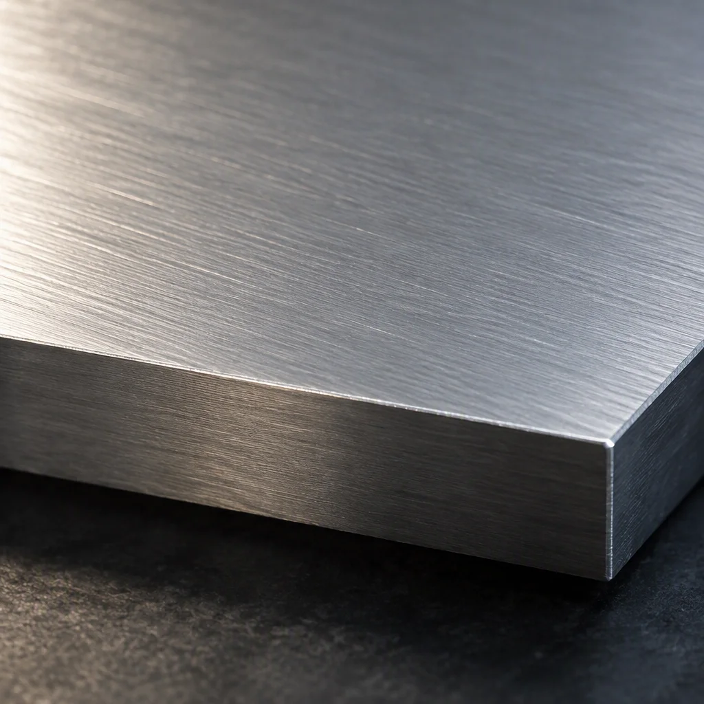
Lapped flat: less material has to be there to bridge the face at all.
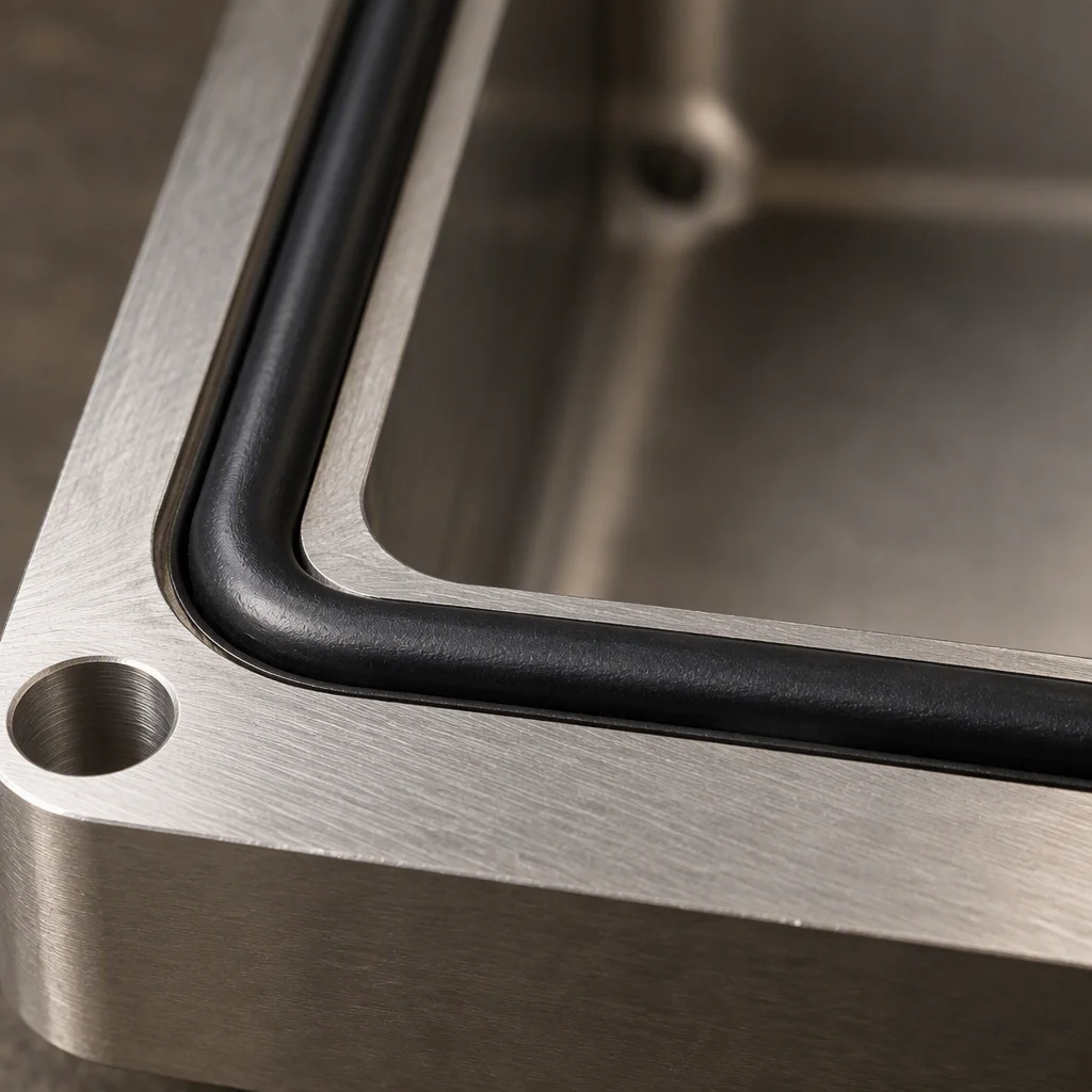
Two jobs on one face: the groove is the seal's, the land is the interface's.
A gasket face is not an interface face. The groove leaks if the interface material is allowed into it, and the interface stops conducting if the seal is relied on to flatten the plate.
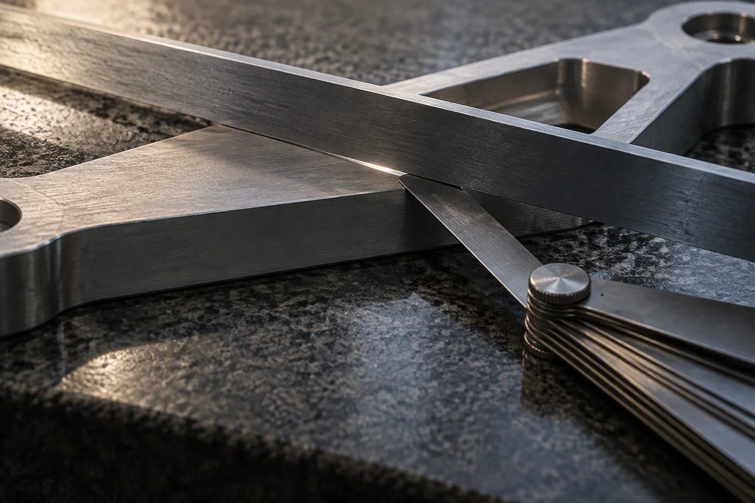
Checked before the material goes on, not after the joint is closed.
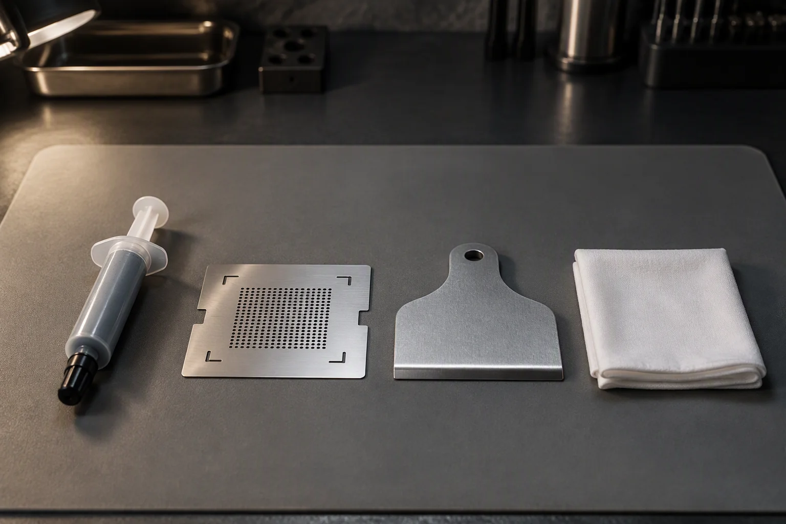
The bench is part of the result: with the loop held to ISO 4406 17/15/12, what the face picks up here travels with it.
What travels with an interface order
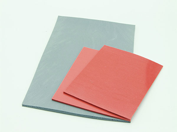
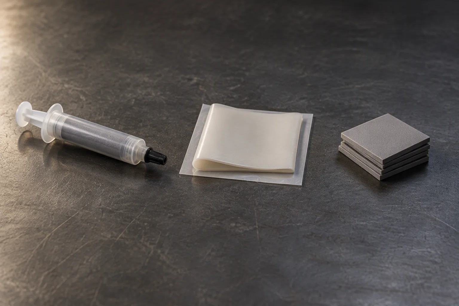
Request the specification file
Four documents are held for this line. Tick what you need and one reply returns them, attached, on the next business day.
- Specification sheet grease and phase change
- EN 10204 3.1 material certificates metal parts
- Thermal and ageing report before and after cycling
- Layer drawings stack order and bond line
One business day, with the file attached.
No other commitment is made on this sheet. Price, stock and lead time are not promised here.
If the form cannot send, this address takes the request instead: sales@ems-cool.com
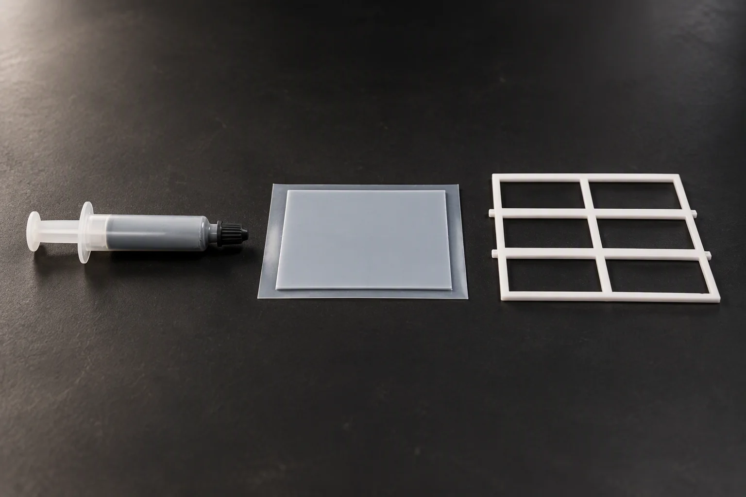
What an interface order contains: the material, its liner, and the retention.
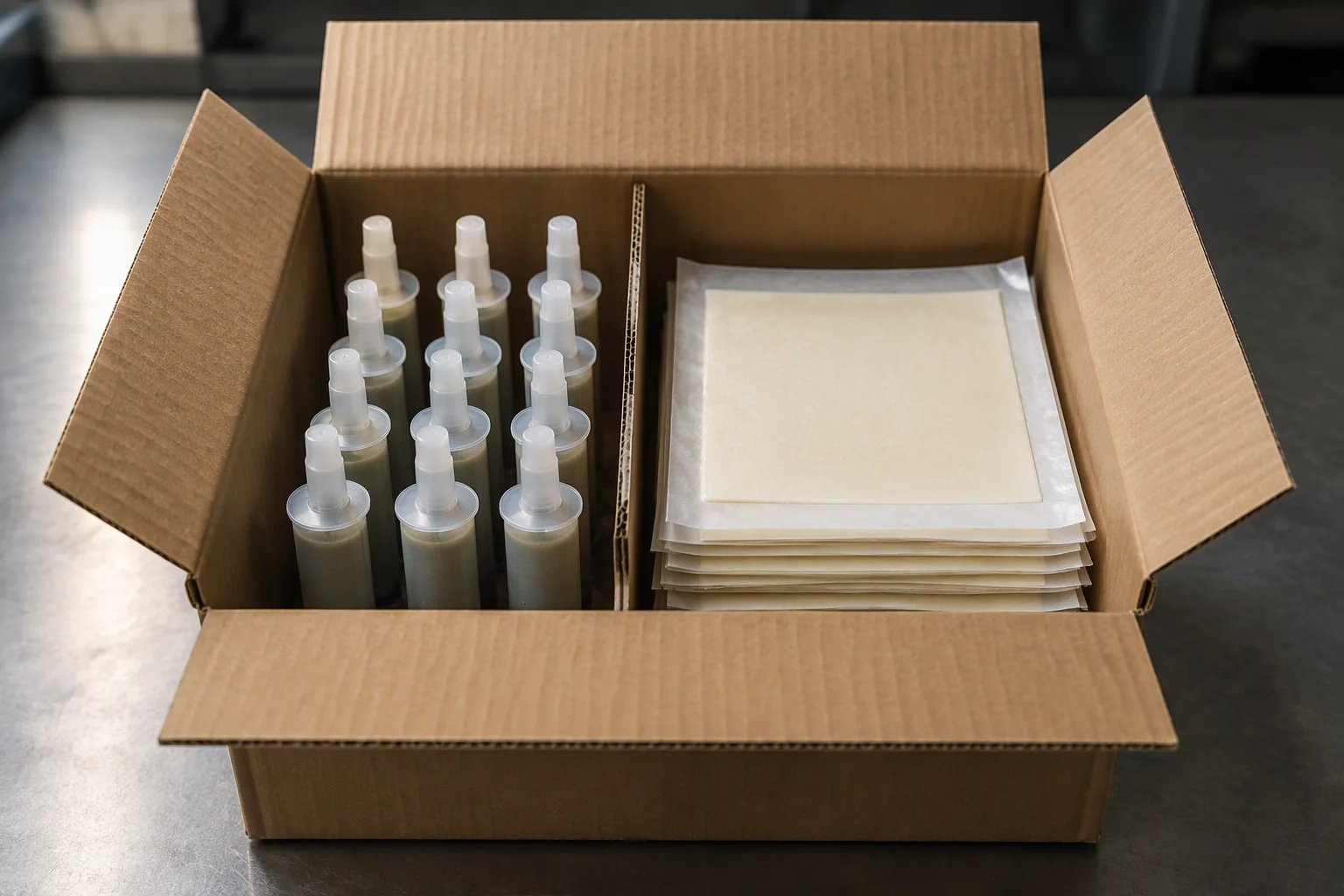
Liners stay on until the joint is being closed, in the hall or at the bench.
