
Commissioning is run by the installing contractor. We supply what it consumes.
The step has three figures written into it: the target the flush has to reach, the point the sample is drawn from, and the rule that says the loop may be charged. Those three are set out below as conditions. The fluid, the elements, the valves and the instruments that read them are the part we ship.
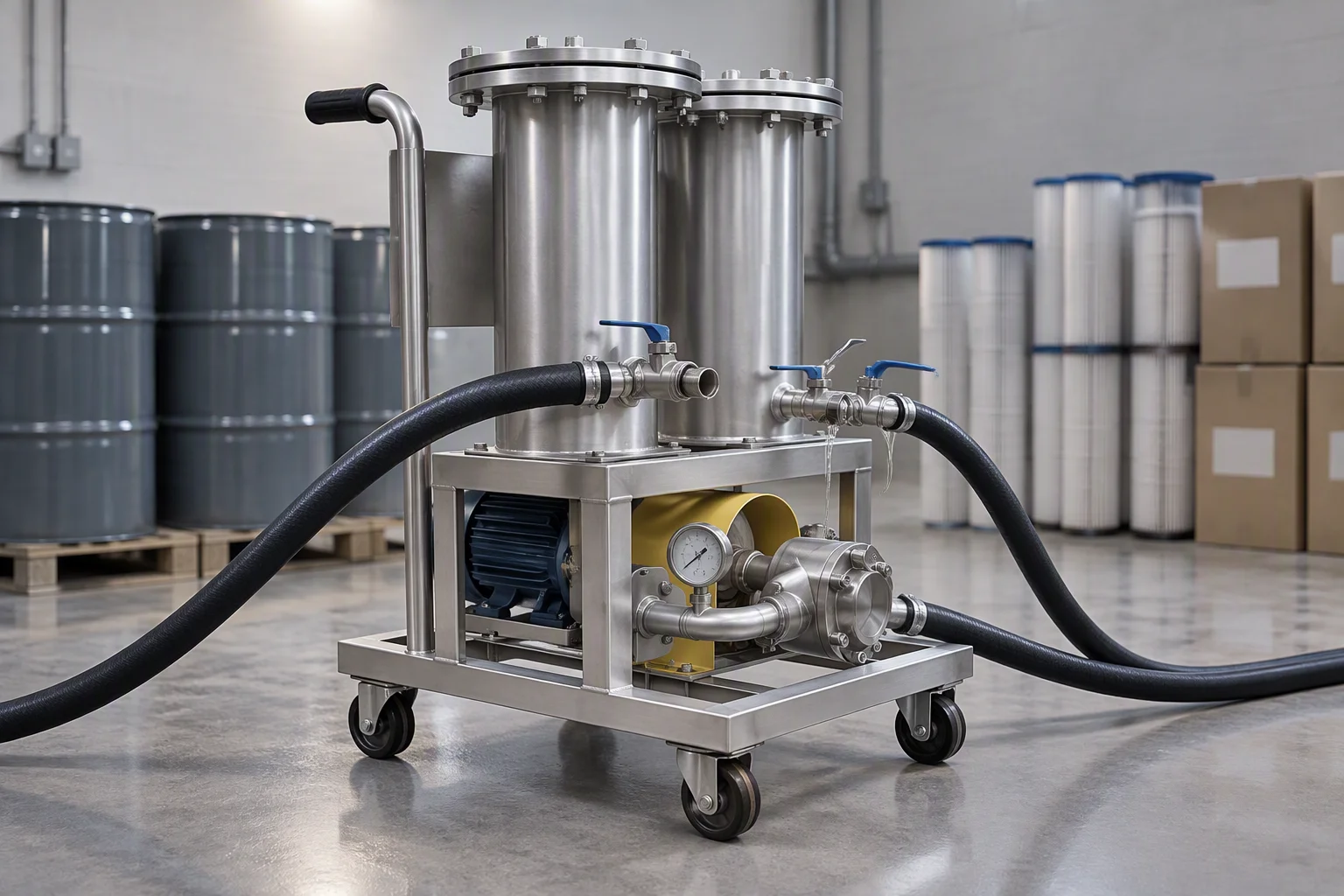
The hour before the charge. Everything on this sheet is either in this frame or has just been taken out of it.
The three figures the step is held to, and the envelope around them
| No | Condition | Value | Unit | Past the edge |
|---|---|---|---|---|
| 01 | Flush target before charge | ISO 4406 17/15/12 | three classes | The owner may write a stricter figure. Then the schedule runs to the owner's number and ours is the floor, not the target |
| 02 | Sampling point on the return | return leg | upstream of charge | Drawn from the tank instead, the sample describes the fluid that has not been round the loop yet, and it reads clean earlier than the loop is |
| 03 | Acceptance the rule | all three classes | same sample | Met at one sampling, not averaged across two. A loop that passes on the second draw has not passed |
| 04 | Flush fluid what is put through | 0.05 – 100 µm | element ladder | The two elements the fluid passes on its way round are drawn from the eight-step absolute ladder; 20 in and 40 in in the standard housings, 10 in on a small branch |
| 05 | Element change the stop rule | 0.5 – 0.7 | bar | Across the housing. Past it the element is bypassing and the loop is being circulated rather than filtered |
| 06 | Water quality read beside the sample | µS/cm · pH | two readings | Particle count says whether the loop is clean; conductivity and pH say whether what is left in it will stay inert once the coolant is in |
| 07 | Loop side the hardware it meets | 1.38 MPa | working | Hose and couplings in the same range as the rest of the loop, burst above 5.5 MPa, coolant quoted −40 ~ +99 °C |
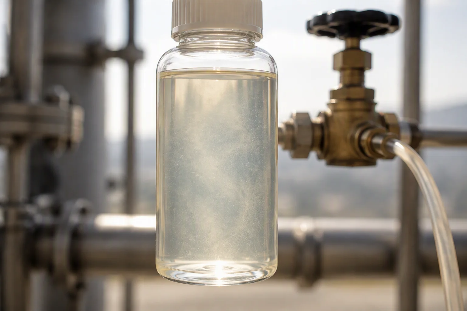
The sample is the only evidence that matters. Everything else on this sheet is arranged to make that one bottle mean something.
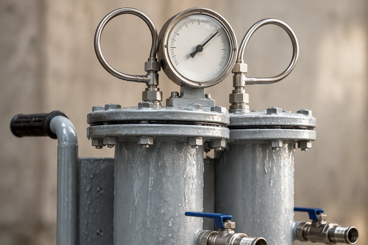
The stop rule, read where it is decided. A climb from the clean-water zero is the only signal that the element is done.
Three ways the step is failed, and what each one looks like
None of these three shows up as a leak. All three are found later, as a conductivity that will not settle, a pump that has to work harder, or a filter that loads in a month instead of a year.
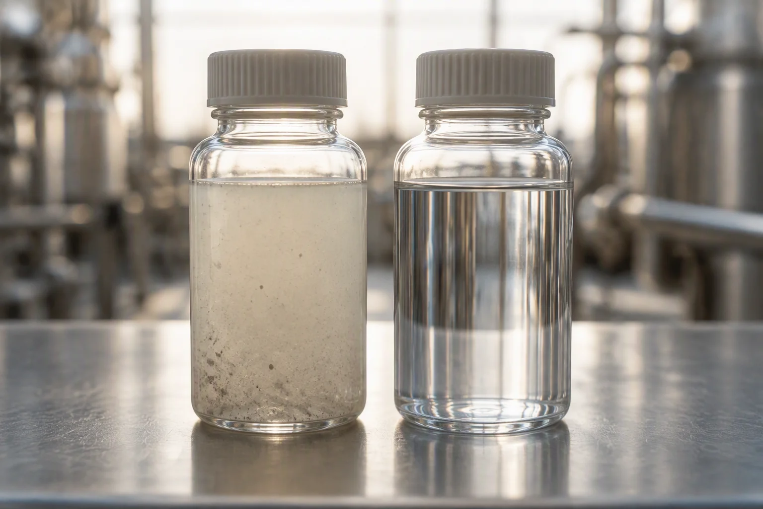
Charged early. The flush was stopped while the sample still carried solids, and they went into the coolant instead of the element.
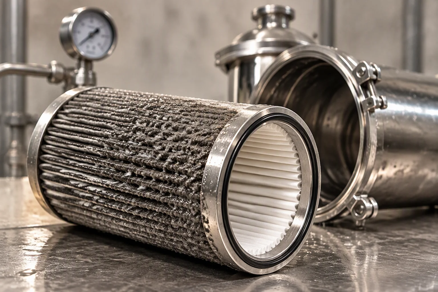
Run past the stop rule. The first stage packed up, flow went round it, and the flush carried on looking normal.
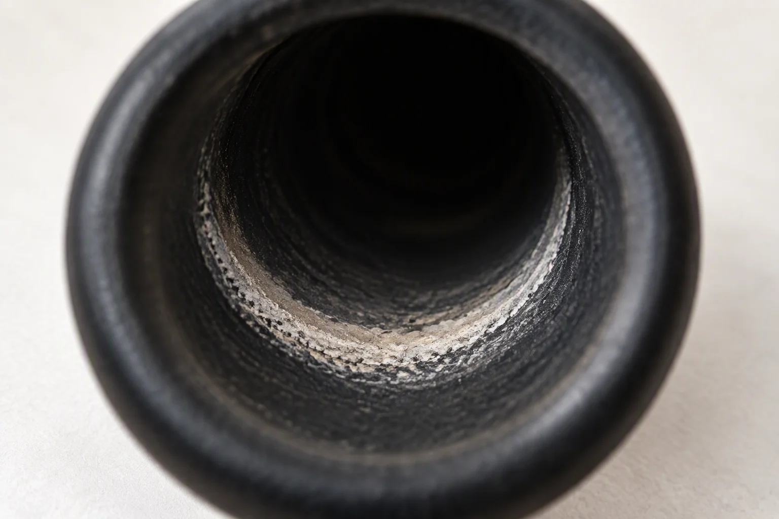
Not drained. What dries in the low side of a run re-dissolves into the charge, and the conductivity moves from the first day.
Checkable before the charge is opened · sample clarity against the light · differential from the clean-water zero · drain point at the low end · conductivity and pH beside the particle count · the element record against the hours run
What the step puts through, against what it meets
| Medium | EPDM seal | EPDM hose | 304 / 316L | Brass valve |
|---|---|---|---|---|
| Flush water, deionised | ||||
| Glycol mix, up to 20% | ||||
| The charge itself | ||||
| Flush fluid residue | ||||
| Coolant above +99 °C | ||||
| Air side, ozone and UV |
Tick within the quoted envelopeDash needs the inhibitor package checked firstCross outside the quoted envelope
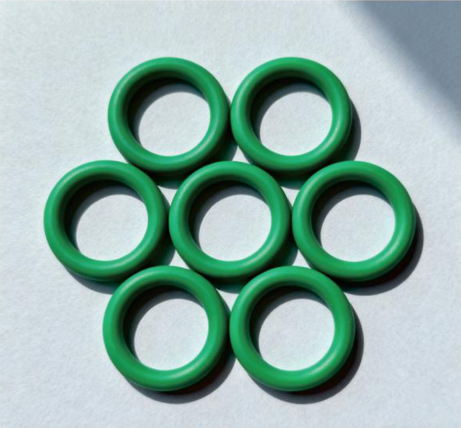
Seals as they arrive. The colour is a compound code, and the compound is what the matrix above is written about.
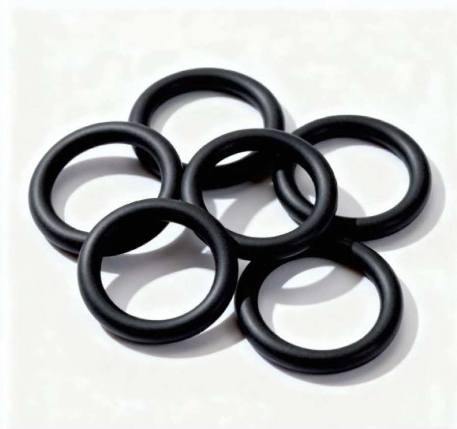
The black compound, EPDM, and the one that carries most of the joints on a flushed loop.
Where each consumable sits once the loop is real
Four places on a real installation decide whether the figures in Schedule A can be met at all: where the flush enters, where the sample is drawn, where the loop drains, and where the instrument is read. All four are marked on the outline drawing that goes with the order.
The step itself is carried out by the installing contractor, on the contractor's programme. What is settled here is the hardware, so that the four positions exist before anybody needs them.
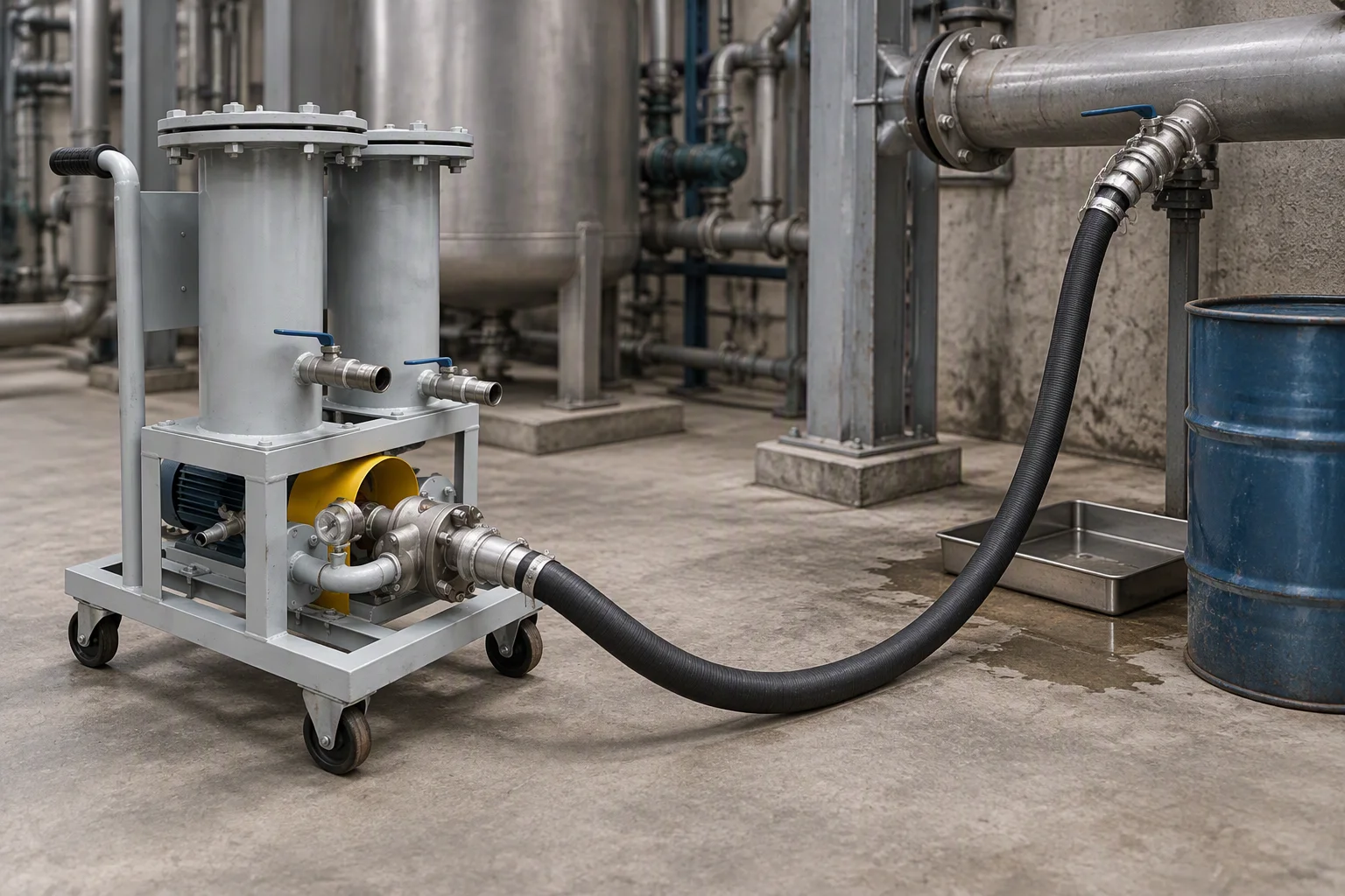
Entry and drain. Low point out, high point in, and a tray under the connection nobody planned for.
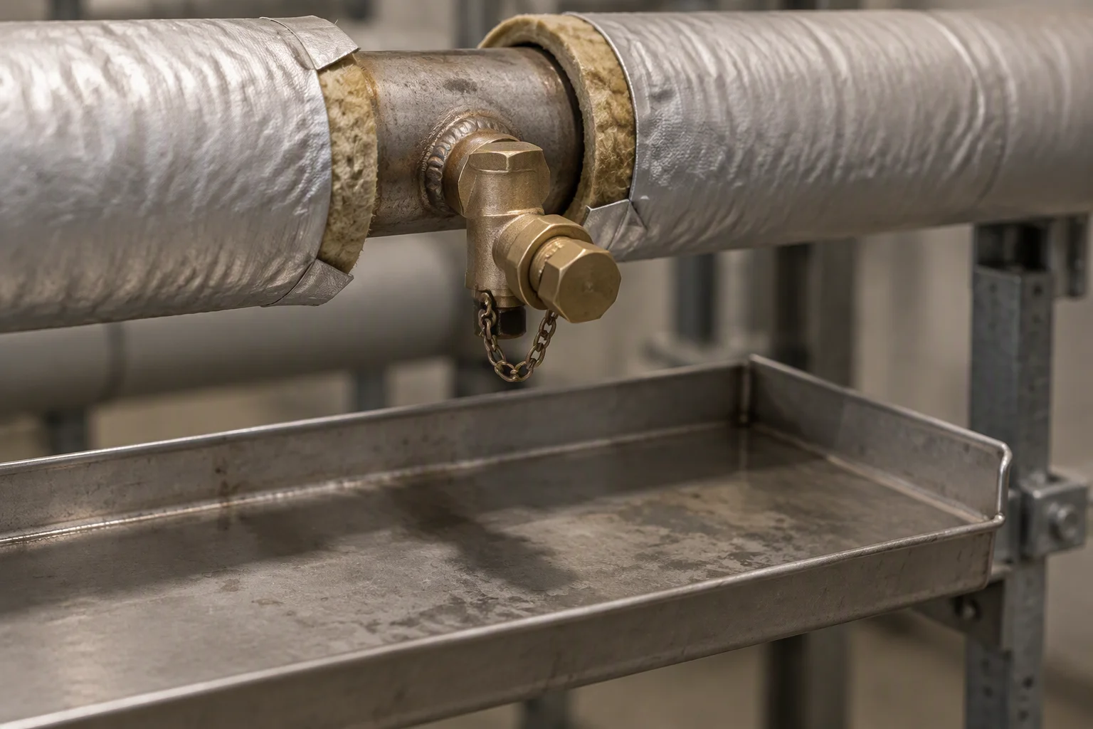
The tap, on the return. Fitted while the pipe was open, not added the day the sample was wanted.
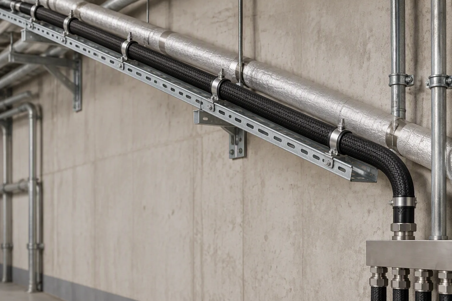
A hose run with no low point in it. Every dip in the run is a place the flush water stays after the drain.
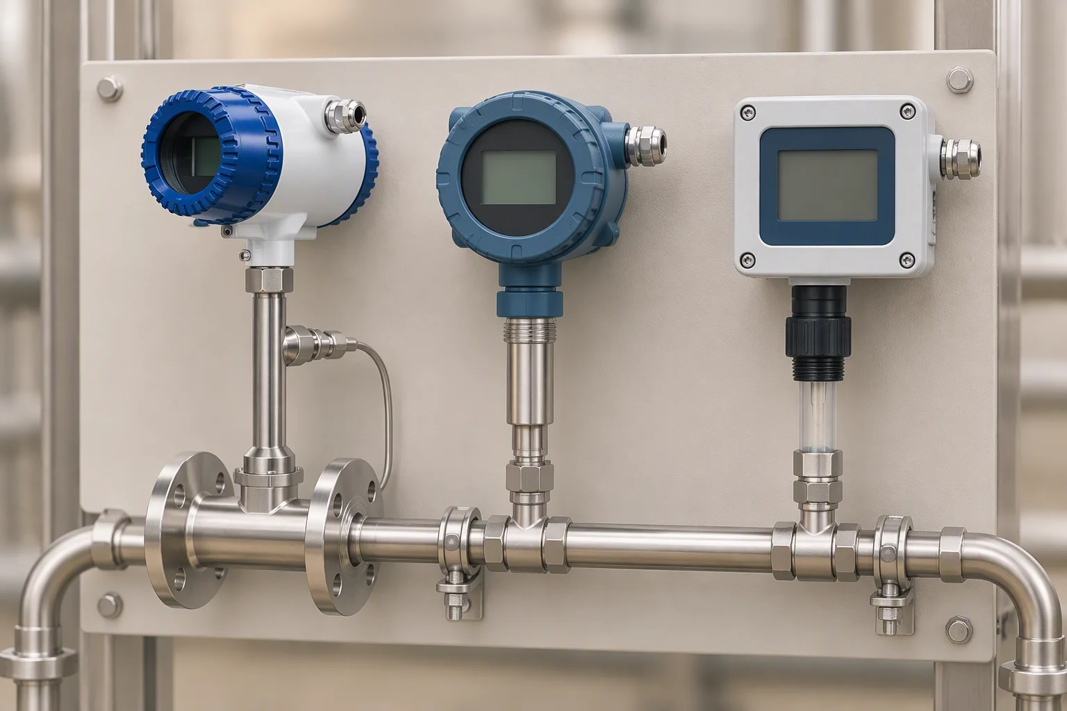
Read where the sample is taken. Conductivity and pH are taken beside the particle count, not days later from a different point in the loop.
What ships with the consumables
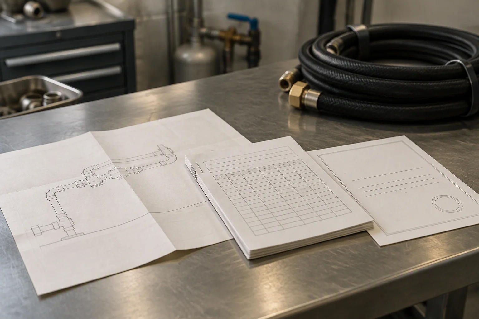
One page of the pack is the one that gets carried up the ladder, and it is the outline drawing.
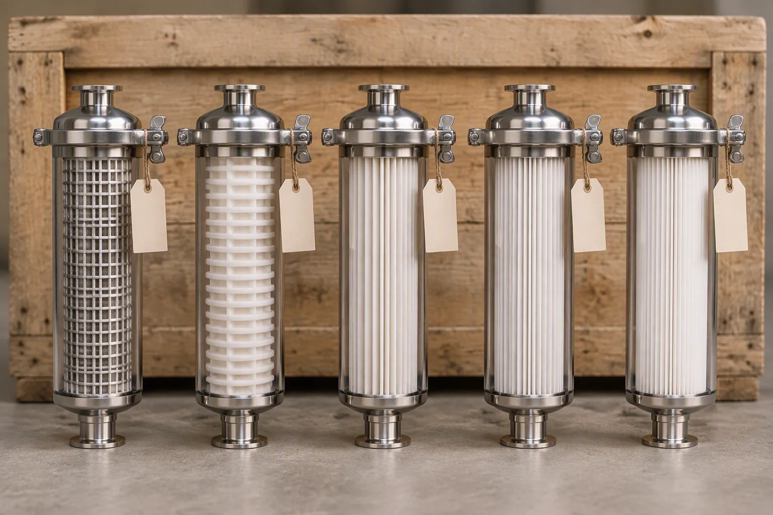
Supplied in order, coarse to fine, so the first stage and the second cannot be swapped by accident on site.
On this line · Fill and flush · Fill and flush carts · Water quality · Fluid quality monitoring
Request the consumable list
The consumable list, the sampling schedule, the outline drawing and the material certificate. Tick what you need.
One business day, with the file attached.
Nothing else on this sheet is promised. Price, stock and lead time are quoted against a request.
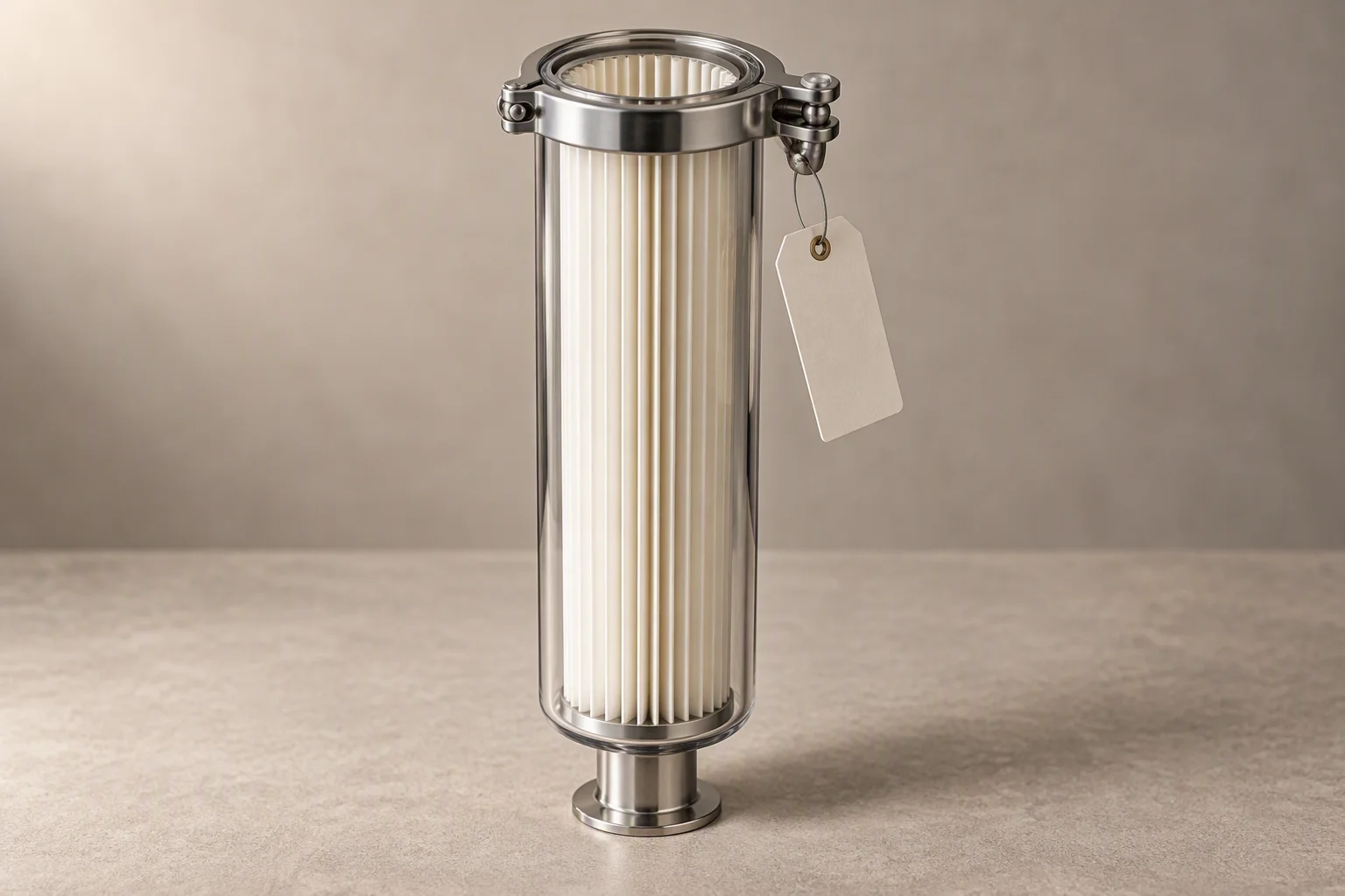
One sleeve, one rating. The two stages are supplied apart because on site they are fitted in one order.
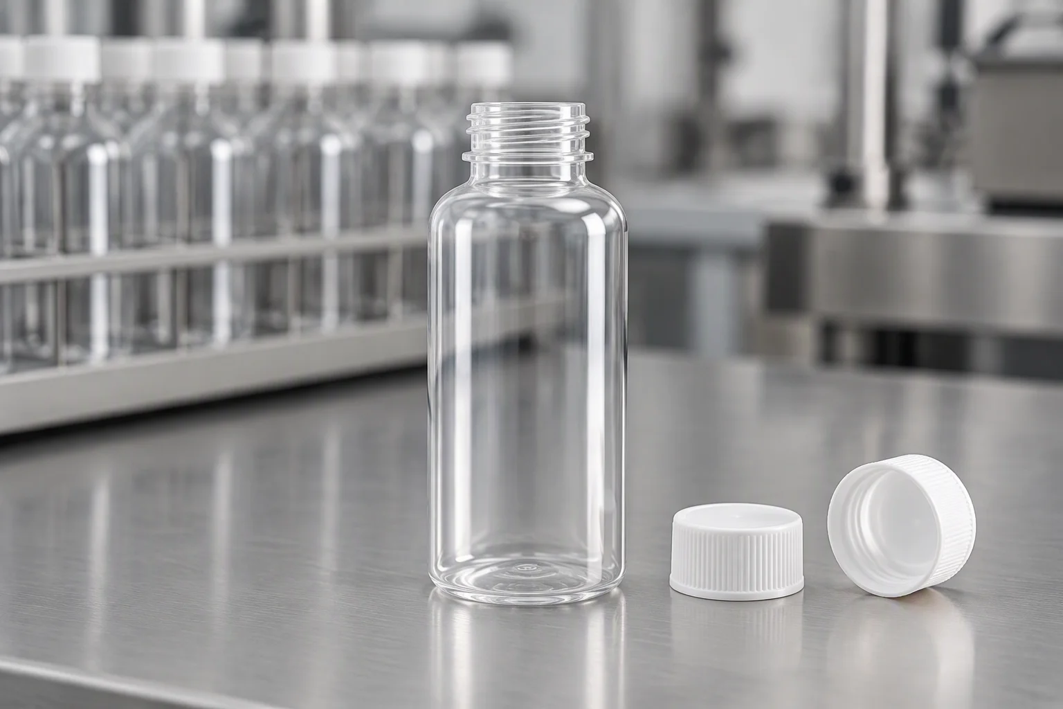
Bottles are supplied clean and dry. A bottle rinsed in tap water is a sample that reports the tap.
