
Fluid quality monitoring for the liquid cooling loop
Conductivity, pH and level are read at the reservoir, and each one is bought on a different criterion. This sheet puts the criteria in the order they actually decide, then the three classes side by side and the limits they are held to.
Cleanliness ISO 4406 17/15/12 Filtration 1 µm absolute Filter change-out 0.5–0.7 bar
The criteria, in the order they decide the choice
A criteria list sorted by the number of parameters a datasheet carries is a list of features. The list below is sorted by what it costs when the criterion is missed: the three at the top each end a loop, and the ones below them only cost money.
It is also the order the questions arrive in. What is the loop being protected from, what is in it, and how clean is it? The range and the output are decided by those three, not the other way round.
| Criterion | What settles it | Why it ranks here |
|---|---|---|
| What the loop is protected from | Corrosion, elastomer attack, or a reservoir drawn down | It decides which of the three readings is worth buying at all |
| What is in the loop | Water, or water with glycol | Decides the wetted material and the cell constant before any range |
| How clean it is | ISO 4406 17/15/12 before first power-on | A reading taken on a dirty loop is a reading of the dirt |
| Filtration rating | 1 µm absolute; the range runs 0.05–100 µm | The probe gap and the particles are the same order of size |
| Conductivity range | Recorded in µS/cm | Sets the cell constant; the wrong one reads off scale at both ends |
| pH range | The loop's own working band | Sets the electrode and the reference, which is where pH goes wrong |
| Level range | Reservoir geometry and the pump inlet height | Sets the stem length; a level sensor is a mechanical fit first |
| Differential pressure | 0.5–0.7 bar at filter change-out | The change-out signal the water reading is judged against |
| Output | 4–20 mA, or Modbus RTU | Decides whether the reading is logged or only seen |
| Wetted material | Stainless, matched to the loop's own parts | A probe that is not the loop's alloy is a corrosion cell |
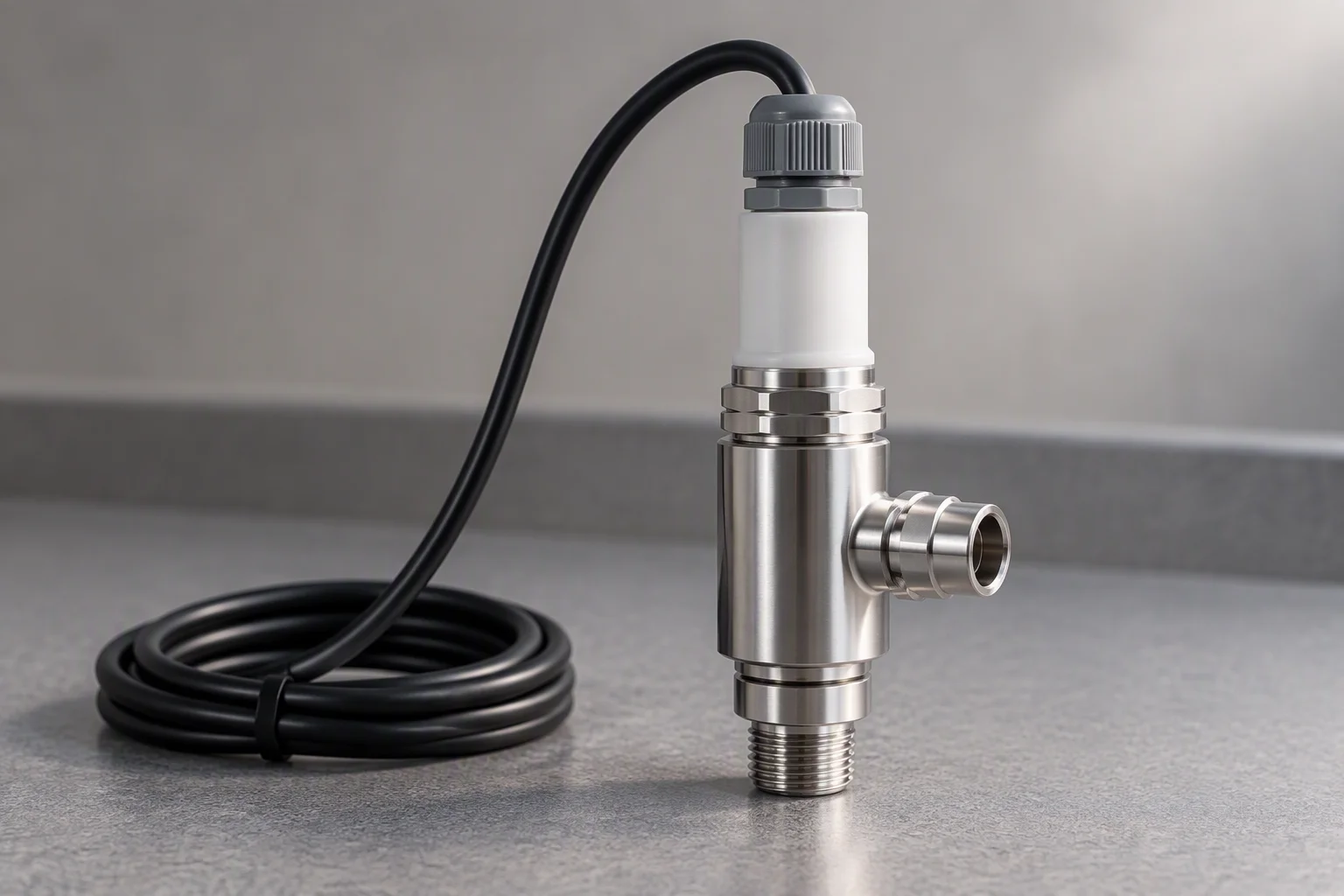
A flow-through cell keeps the probe wet and the reading comparable.
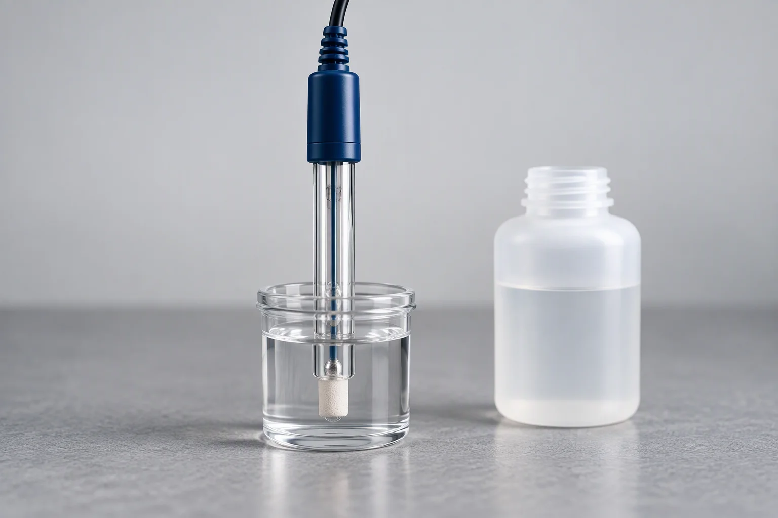
The junction has to stay wet. An electrode stored dry reads a different loop.
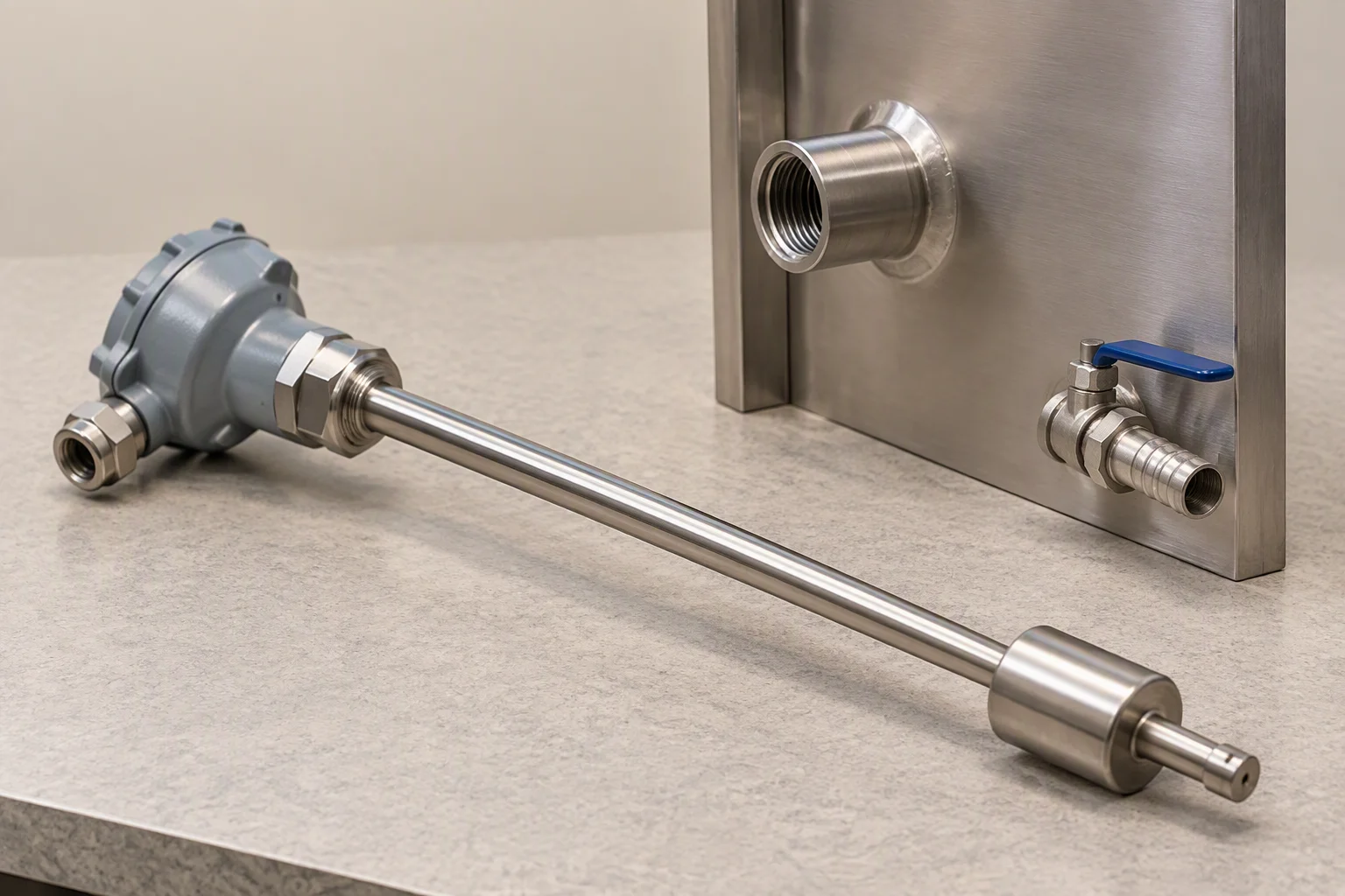
The stem is measured to the pump inlet, not to the bottom of the tank.
Read next · Water quality · Design guides · Telemetry
The three classes, in one frame
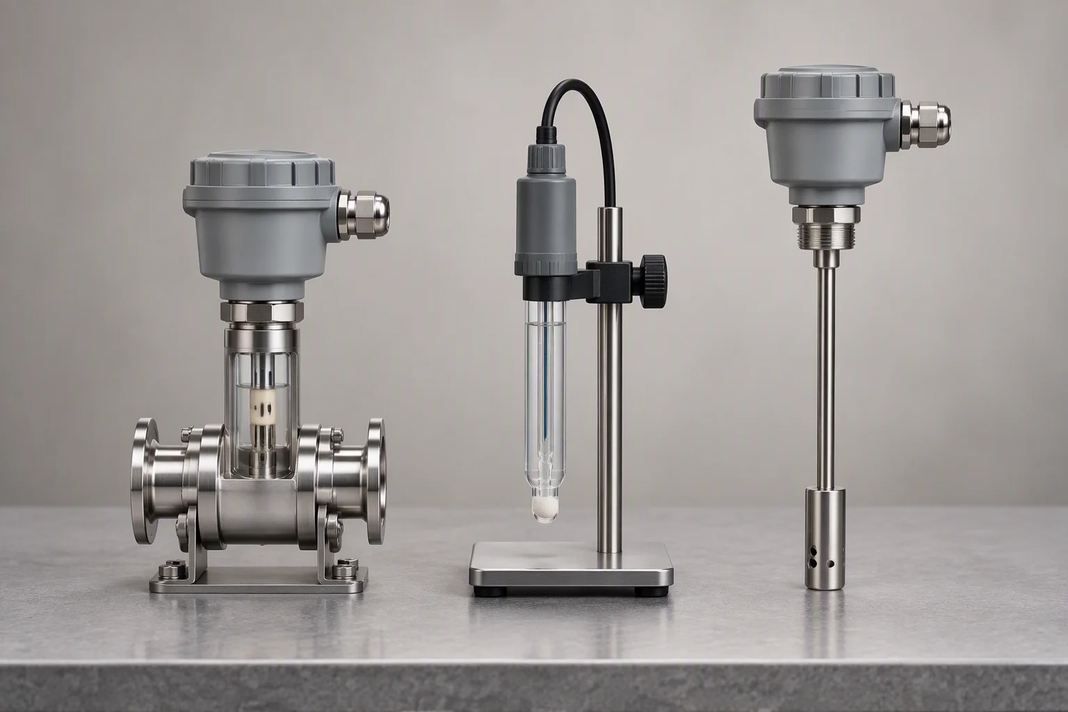
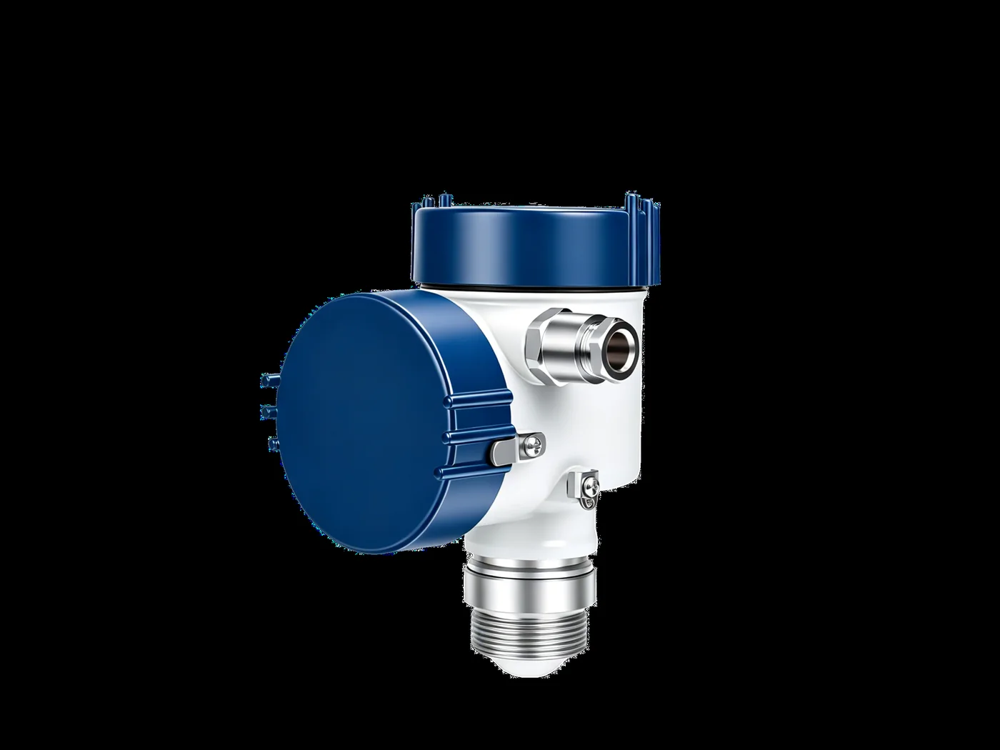
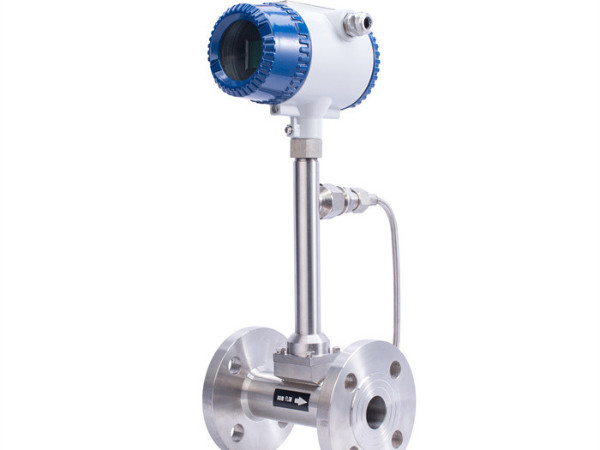
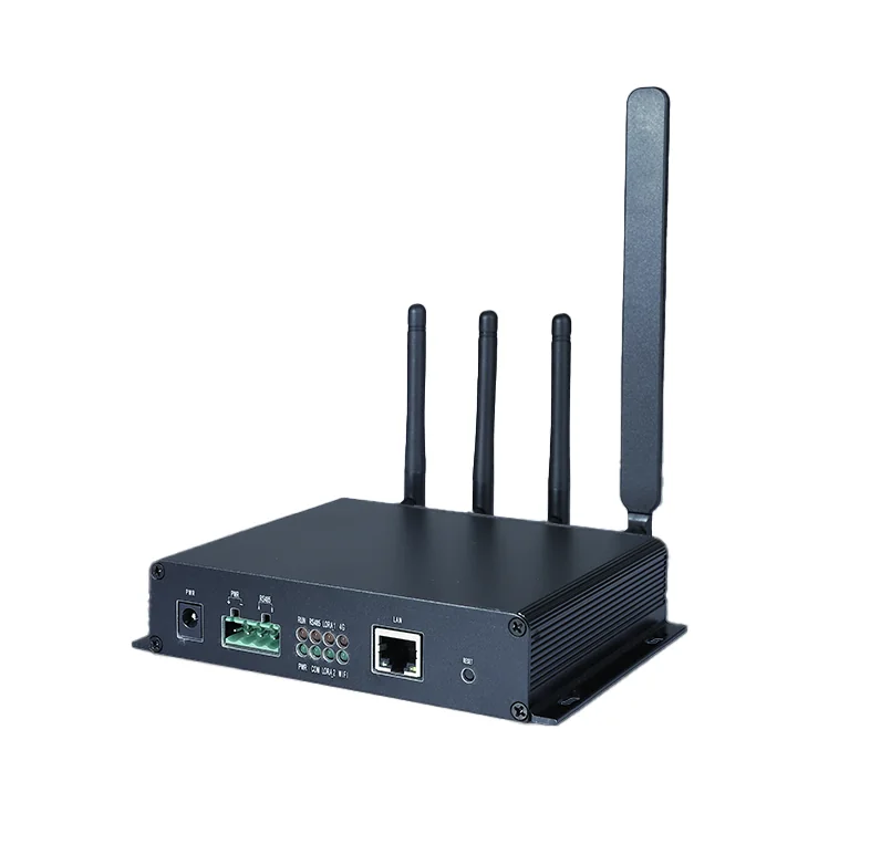
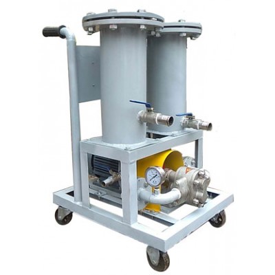
Three classes, one bench. What separates them is where the sensing surface is.
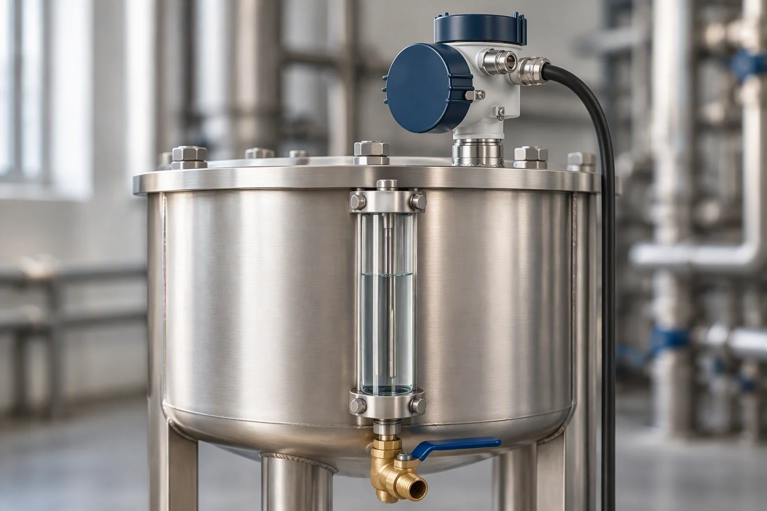
Mounted at the reservoir, because that is where the fluid is quiet and the level is known.
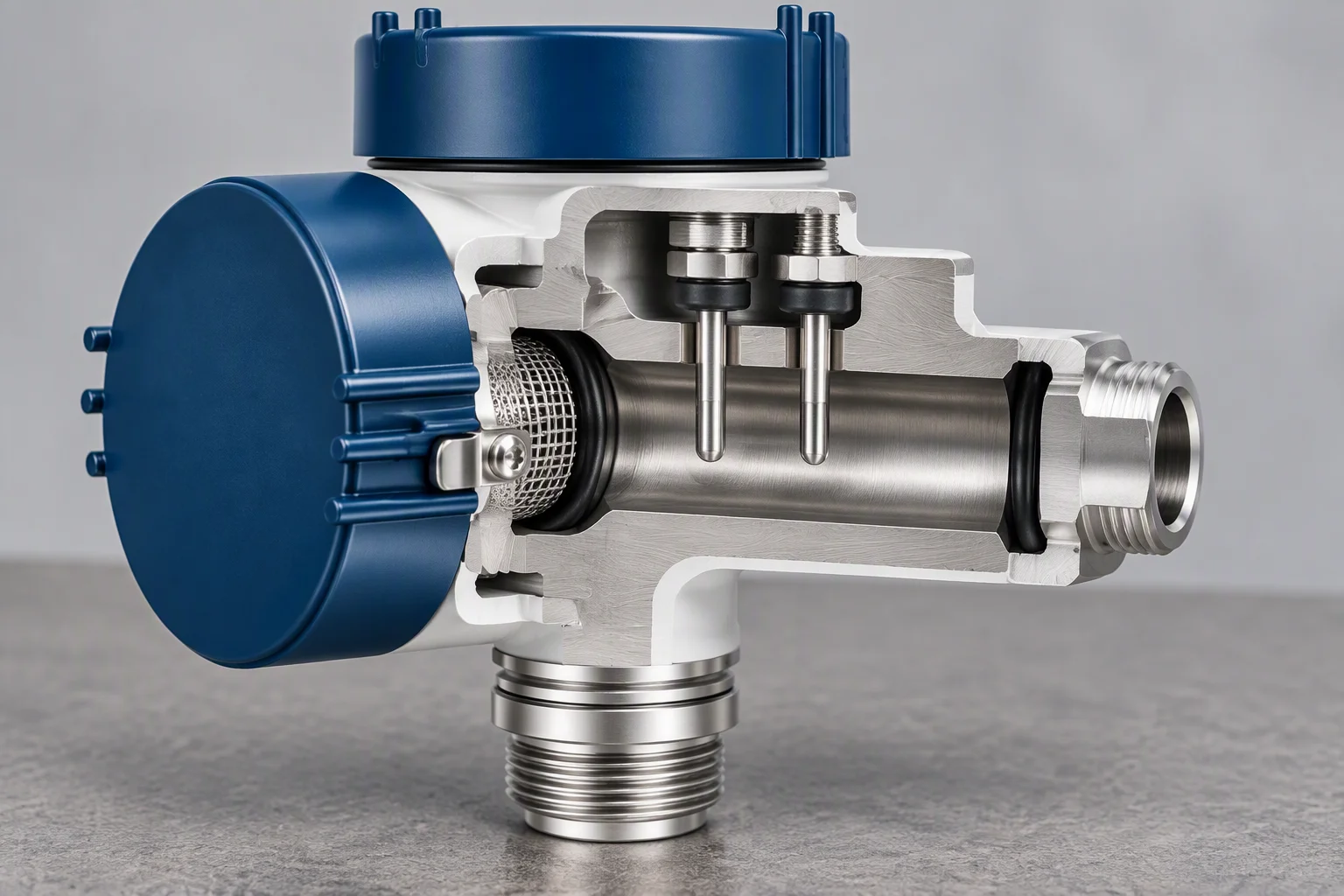
The cell sets the constant. Two electrodes and a fixed bore decide what a µS/cm means here.
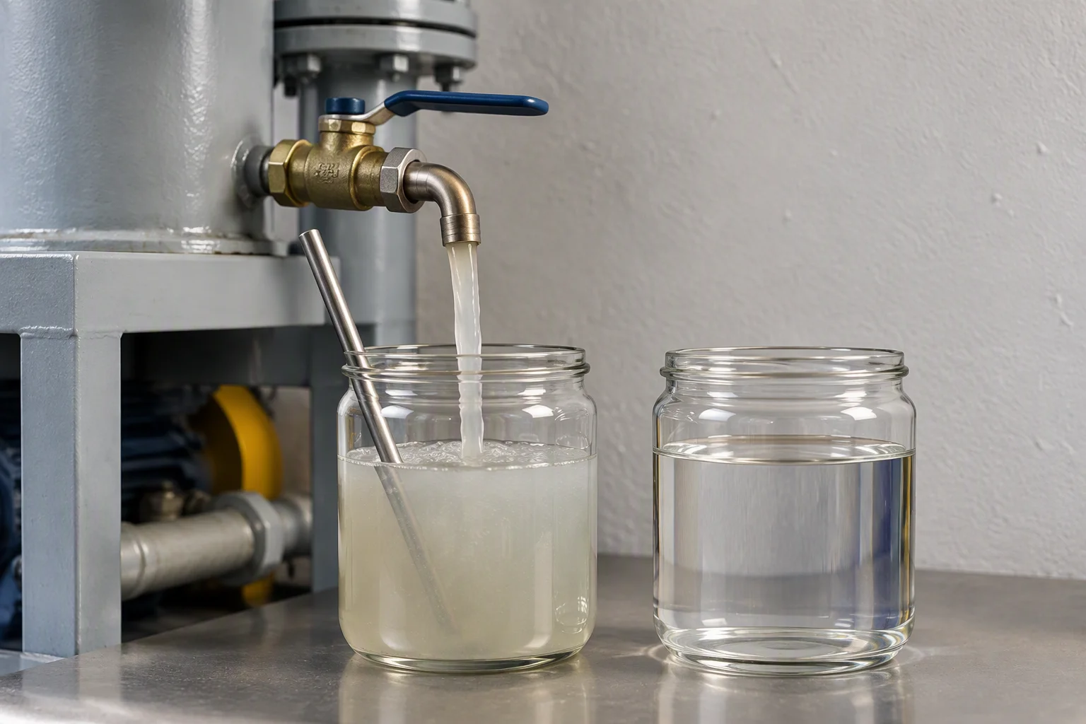
A manual sample is the reference the inline reading is checked against, once a quarter.
Read next · Coolant filtration · Commissioning · FAQ
The limits the instruments are held to
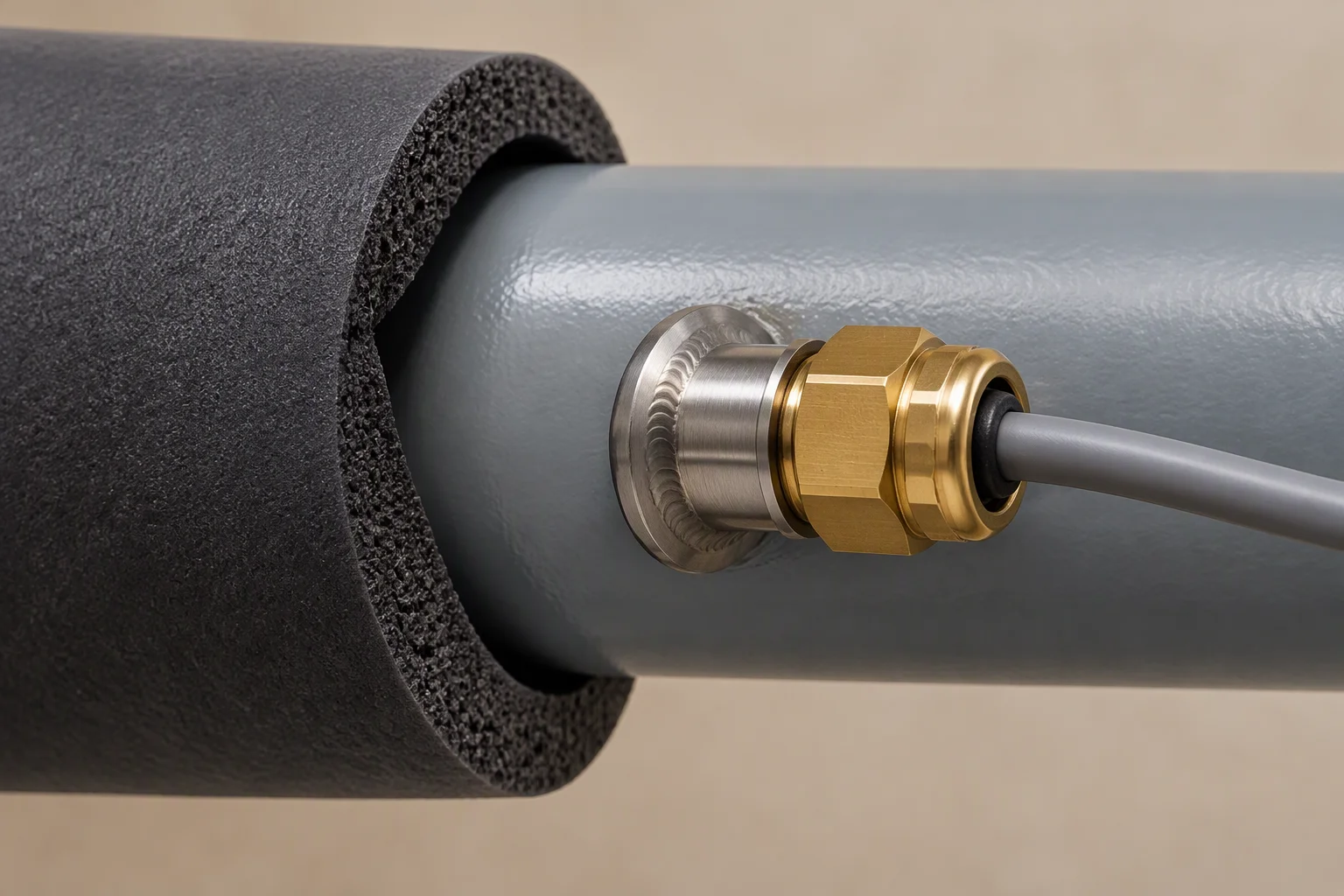
The hot end of the range is a seal problem before it is an electronics problem.
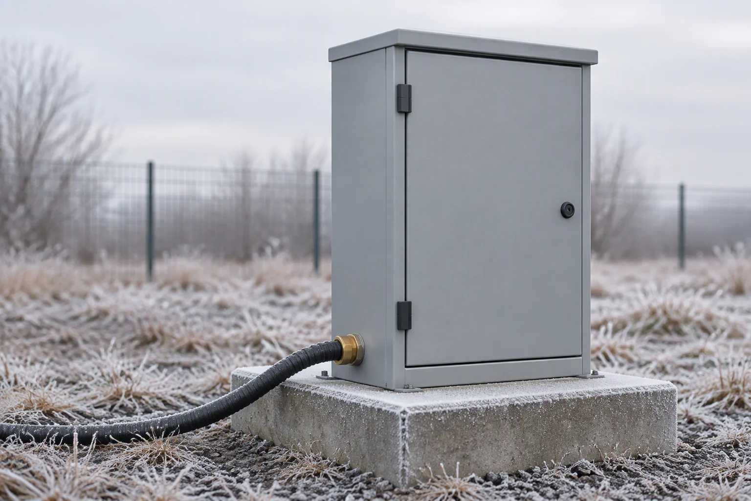
At an unmanned site the ambient range decides the housing, and the housing decides the year.
Read next · Edge & telecom · Notes on ISO 4406 · Capabilities
The mistakes that cost the most, and what each one costs
- Reading conductivity straight after a top-up. The make-up water reads low and hides the trend it was installed to follow.
- Calibrating pH against a buffer that has stood open. The loop is then dosed against a number that moved before the dosing did.
- Fitting the level sensor to the tank wall instead of to the pump inlet. The pump cavitates while the tank still shows level.
- Judging the element by the supply pressure instead of the differential. The supply pressure moves with everything else on the loop.
- Changing the element on a calendar. The differential decides the change-out, and a loaded element is the only signal that matters.
- Comparing one site's µS/cm against another's. The reading belongs to the loop it was taken on, and so does the baseline.
Every one of these is a reading that was taken, logged, and then believed for the wrong reason.
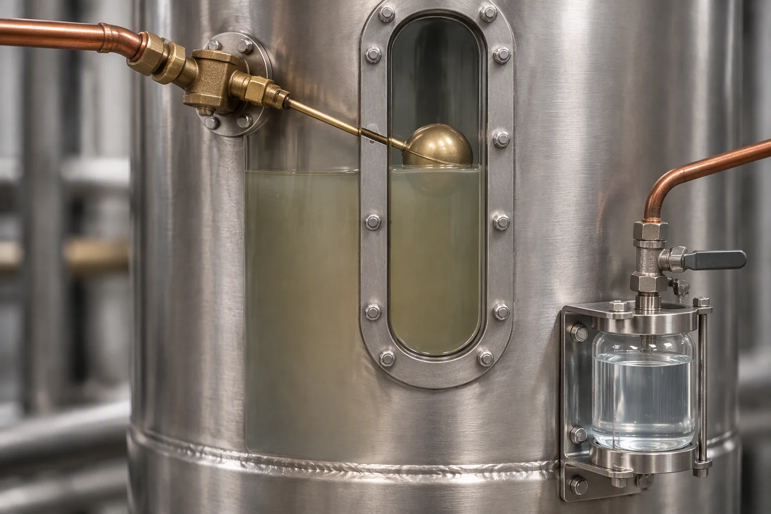
Make-up water dilutes the reading as well as the coolant.
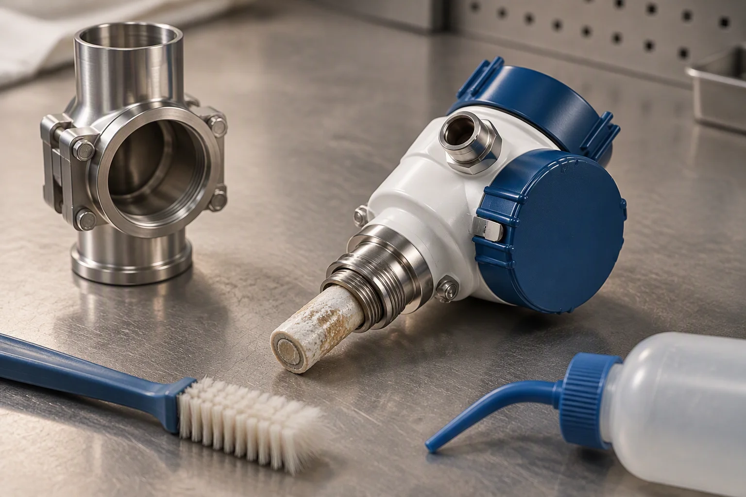
A probe left dry between fills reads the next loop as if it were a different fluid.
Read next · Design guides · Notes · FAQ
Documents and packing, per shipment
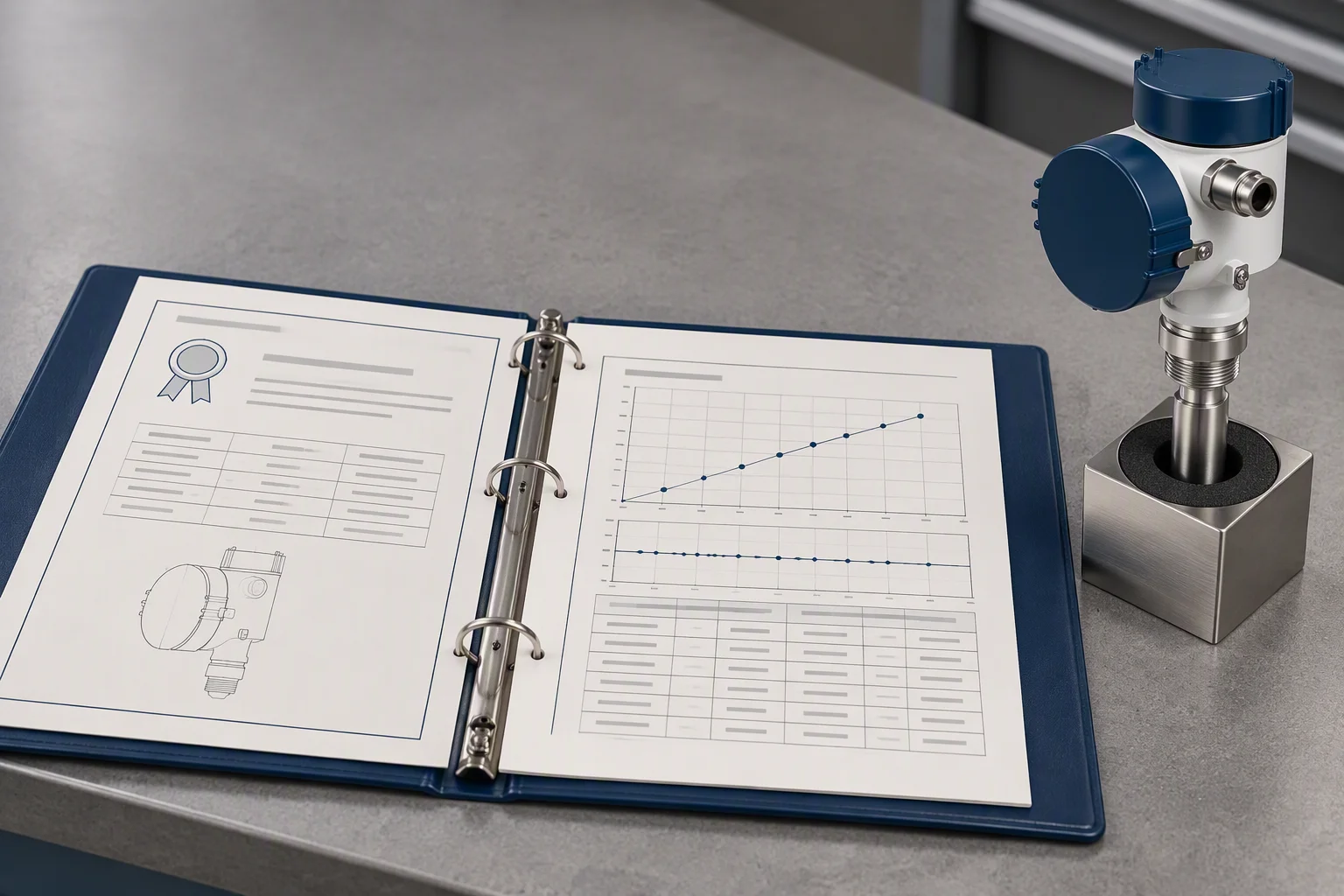
The calibration record and the certificate are signed together, not on separate days.
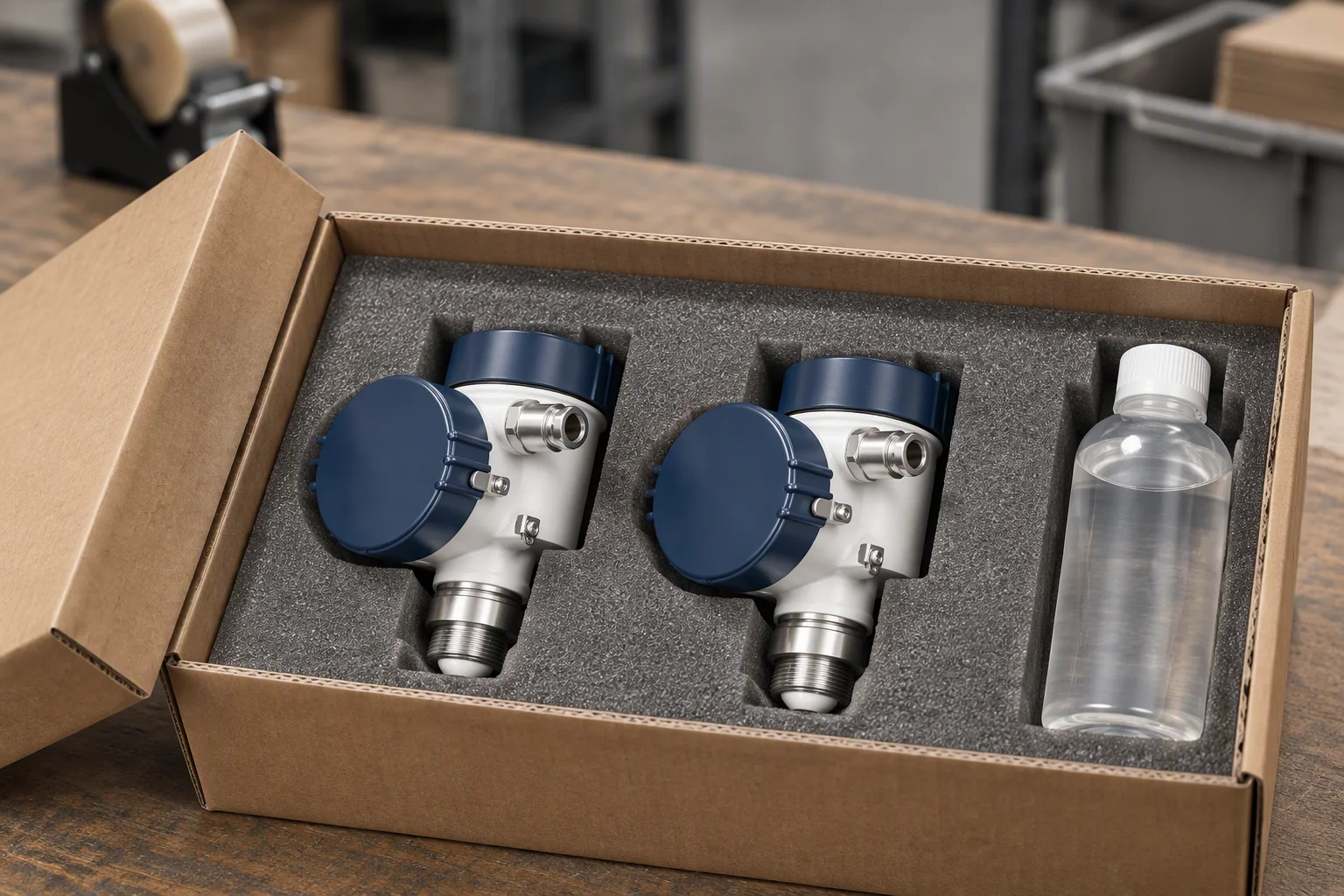
Probes ship wet, in their storage fluid, for the reason the mistake above describes.
Read next · Quality & inspection · Legal · Contact
Four documents are held for this sheet. Tick the ones you need.
Tick a document, name the coolant and the range you are fitting, and the file comes back attached.
One business day, with the file attached.
Nothing else on this sheet is promised. Price, stock and lead time are not promised here.
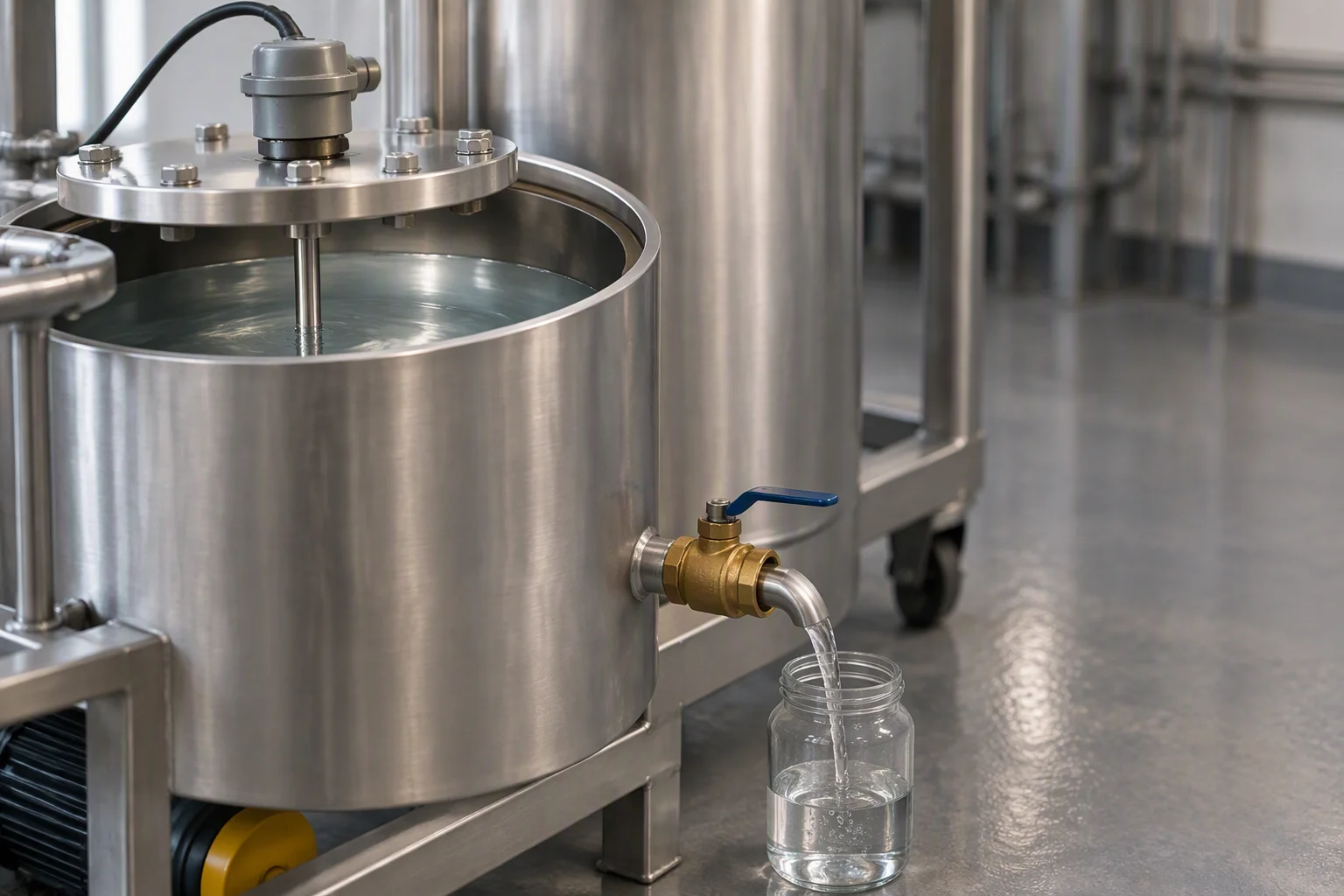
The reading is taken with the loop at working temperature, not on a cold fill.
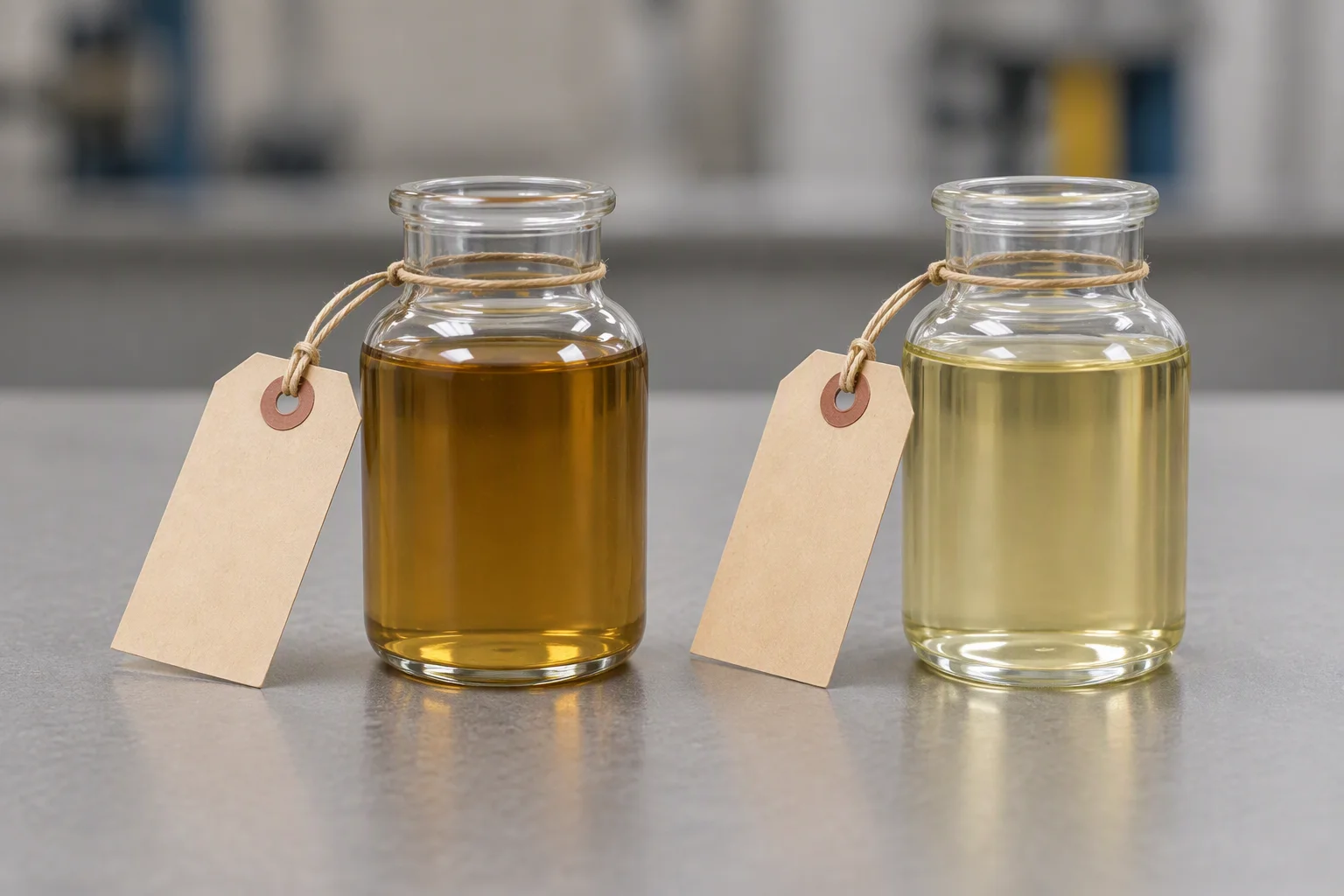
Two tagged pots are a baseline. One number on a screen is not.
