EMS-Trade
Cooling
Loop consumables

Document ECT-01 · REV C · ISSUED 2026-09 Six lines · 48 sheets

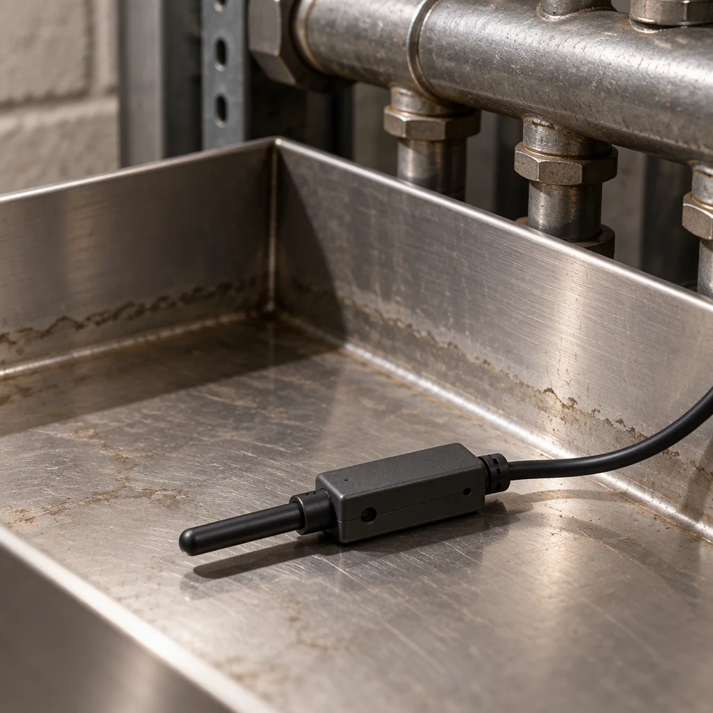
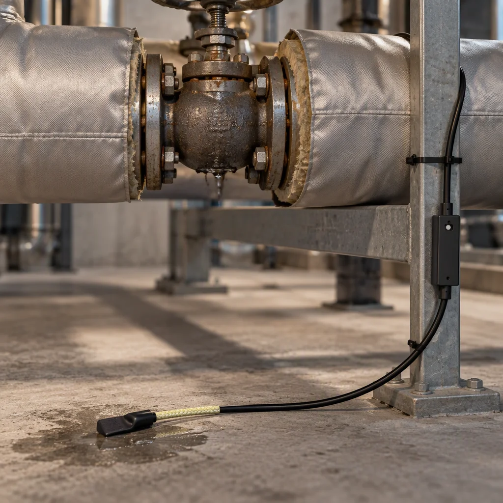
A point sensor resting in a steel drip tray in close view, its sealed body on a short lead with the lead running out of frame
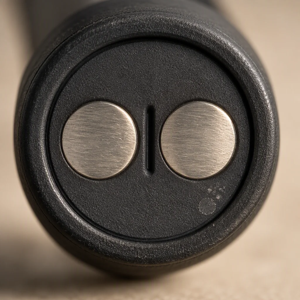
The sensing face of a point sensor in close view, two metal electrodes set flush in the underside of the sealed body
A point sensor laid under a manifold beside a valve gland, the lead cable tied along the pipe support away from the drip line
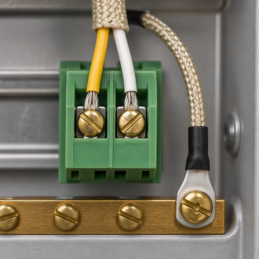
The lead of a point sensor landed on a pair of controller terminals, the two cores under adjacent screws with the shield on the earth bar
Sheet 21 · Line 01 of six · construction

Point sensors

Fixed-point monitoring under a coil, a joint, a valve gland or a pump seal. One sensor occupies one channel and reports a state, not a position.

01

What is inside the body, in section

Section 01 · the section

Section through a point sensor: jacketed body, seal, sensing element, potting, lead and termination The body sits lowest in the tray. Behind the sensing face, potting holds the element at a fixed height. The seal closes the body against the lead, the lead leaves through a gland, and the termination lands on one pair of terminals. tray floor Body Potting Element electrodes Seal Gland Lead Terminal to controller 01 02 03 04 05 06

Key

  1. 01Body: the sealed jacket that sits lowest in the tray.
  2. 02Potting: holds the element at a fixed height.
  3. 03Element: the two electrodes behind the sensing face.
  4. 04Seal: closes the body against the lead.
  5. 05Gland: where the lead leaves the body.
  6. 06Termination: one pair of terminals, one channel.
FIG 01 ·

Six layers, outermost first. Each callout is one row of the layer table in section 02.
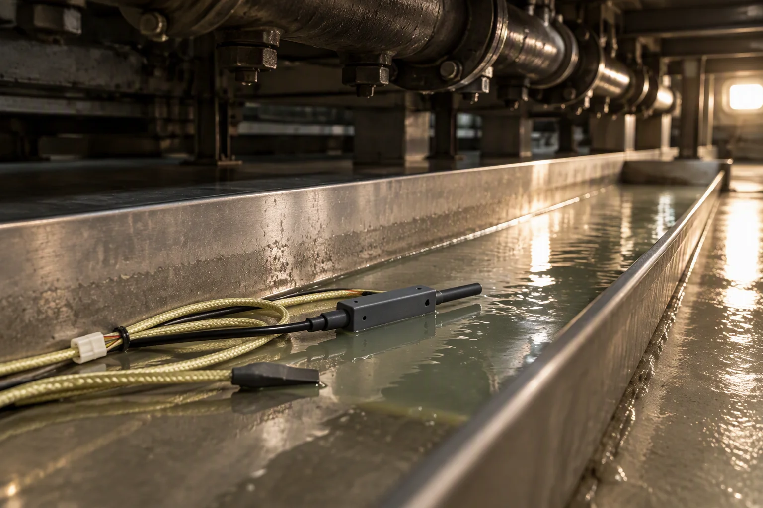
A wide view along a steel drip tray under a pipe manifold, two point sensors lying in the tray with a shallow pool of coolant between them
FIG 02 ·

In service the body lies flat in the tray, below the drip line and ahead of the drain.
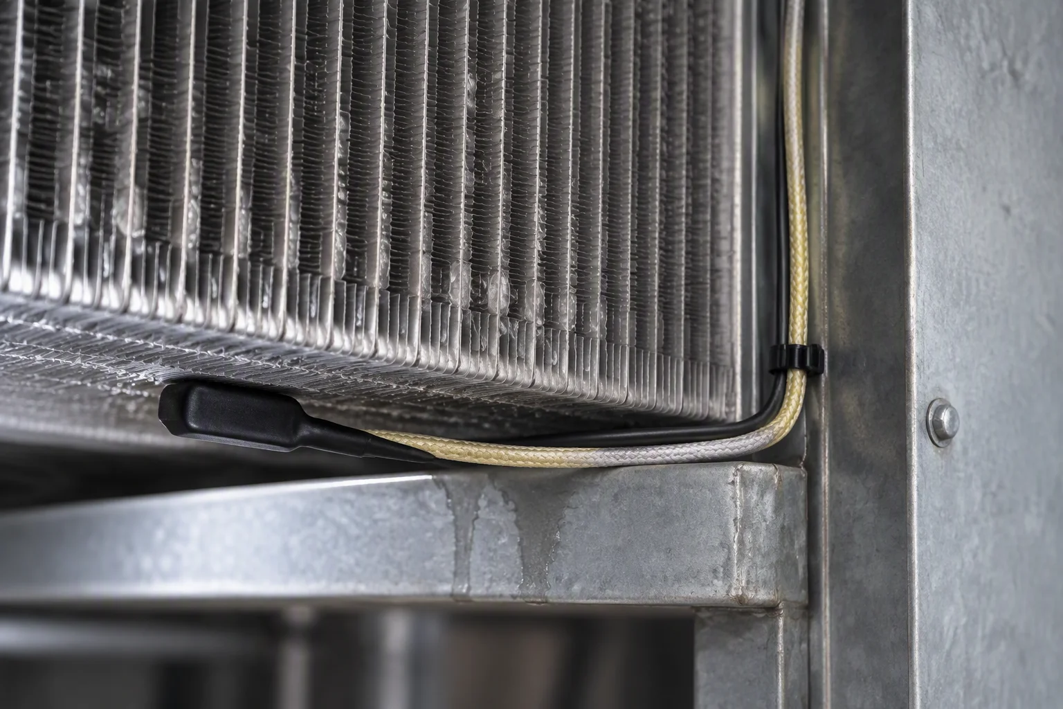
A point sensor laid on the underside of a cooling coil in close view, the coil fins above it and the lead tied back along the frame
FIG 03 ·

Under a coil: the sensor sits where condensate and a weep both arrive.
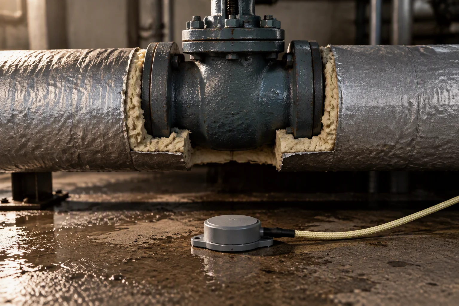
A point sensor placed directly under a valve gland on an insulated pipe, the insulation cut back above it and the lead running clear
FIG 04 ·

Under a gland: one sensor answers one joint, with no calculation in between.

Read next · Locating sensing rope · Controllers

02

The layers, in the order they are built

Section 02 · layer schedule

The table is in layer order, from the face that touches the tray outwards to the panel. Alphabetical order would separate the two layers that have to be read together: the element and the potting that fixes its height.

A point sensor carries no locating calculation, so nothing in it converts a measurement into a distance. What it does carry is the state of one place, and the layers below are what keep that state from being reported before water arrives.

Layer schedule · outermost first, as built
No Layer What it does Figure
01 Body Sits lowest in the tray and keeps dust and metal particles away from the element one pair of terminals
02 Potting Fixes the element at a height the tray can actually reach, so a shallow pool is enough fixed depth
03 Element Two electrodes behind the sensing face; water bridging them is the whole measurement 30 s alarm
04 Seal Closes the body against the lead, so water reaches the face and not the terminations sealed to the lead
05 Lead Carries the channel out of the tray and back to the panel along the pipe support 4–20 mA, relay
06 Termination Lands on one pair of terminals, so a rope run and a point sensor are interchangeable 4 · 8 · 16
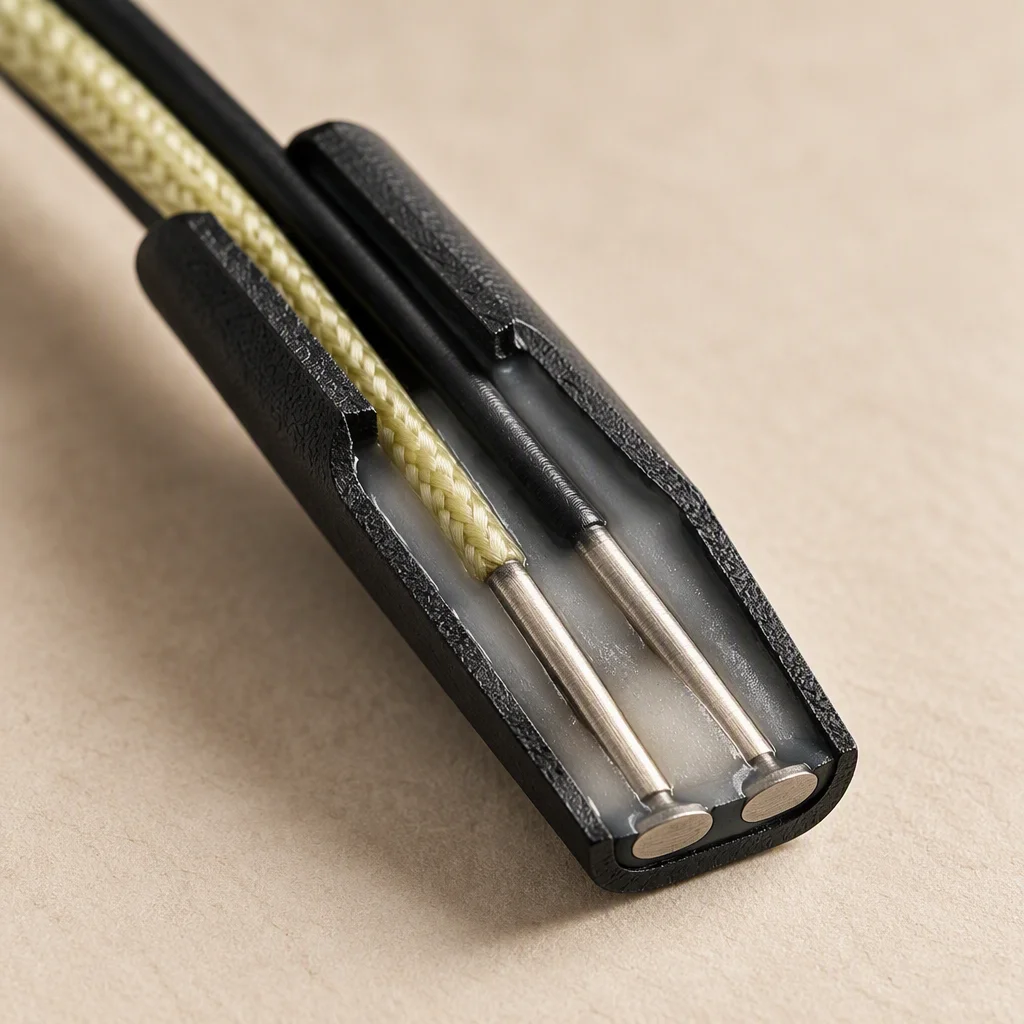
A point sensor cut lengthwise on a bench, the body, the potting behind the face and the two electrodes all visible in the cut
PL 01 ·

Cut lengthwise: the potting fills the body behind the face, with no void for water to sit in.
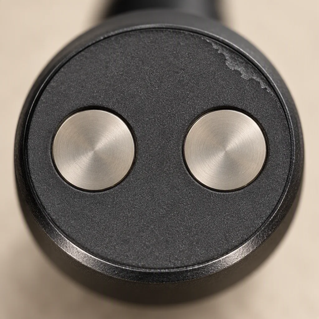
The underside of a point sensor in extreme close view, potting flush around the two electrodes and the body edge chamfered
PL 02 ·

Flush at the face: nothing to catch a drip short of the electrodes.

Read next · Accessories · Quality & inspection

03

The sequence, and what it is checked against

Section 03 · process

01 First article A sample set built and inspected, with the first-article inspection record. 7–10 days.
02 Batch build Body, potting, seal and lead assembled as one batch, not one at a time. 25–35 days.
03 Wet test Each sensor wetted and its channel timed to the alarm. 30 s including the locating calculation.
04 Paper EN 10204 3.1 on the metal parts; the batch number travels with the crate.

The sequence is short because the device is small. What takes the time is the wet test at the end of it, which cannot be sampled: a sensor that is going to report a drip has to be wetted to prove it.
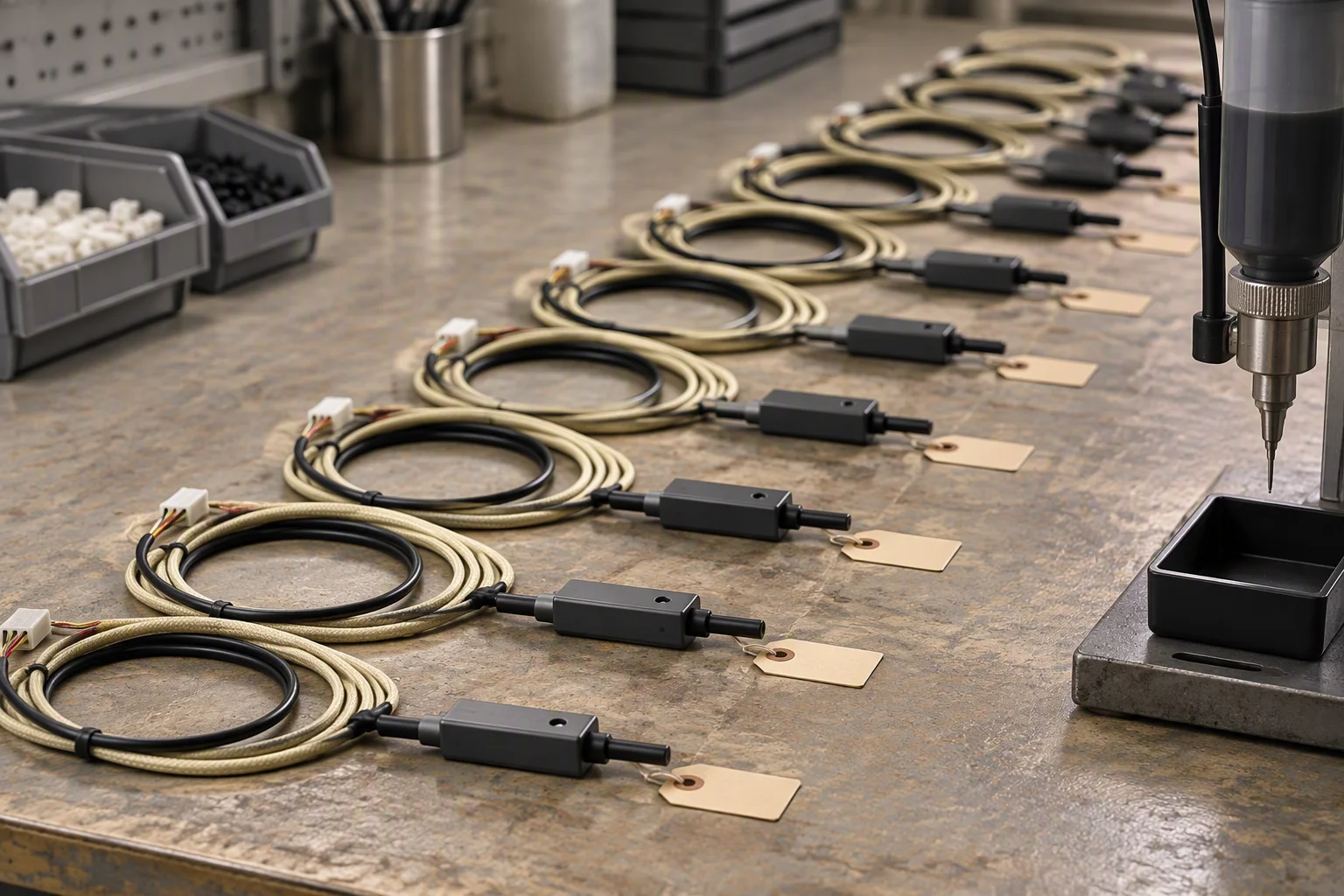
An assembly bench with bodies laid in rows, each on its lead, and a potting dispenser at the near end of the bench
FIG 05 ·

Laid out as a batch: the leads stay numbered from this bench to the crate.
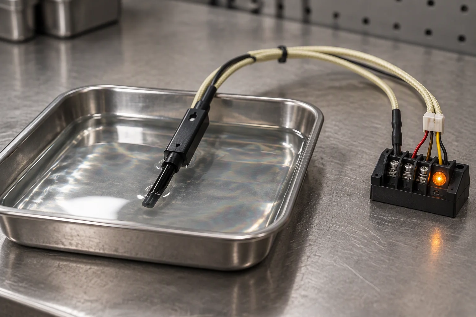
A point sensor sitting in a shallow tray of water on a test bench, its lead clipped to a terminal block with an indicator lit
FIG 06 ·

Wet test: every unit, not a sample. The channel is timed to the alarm.
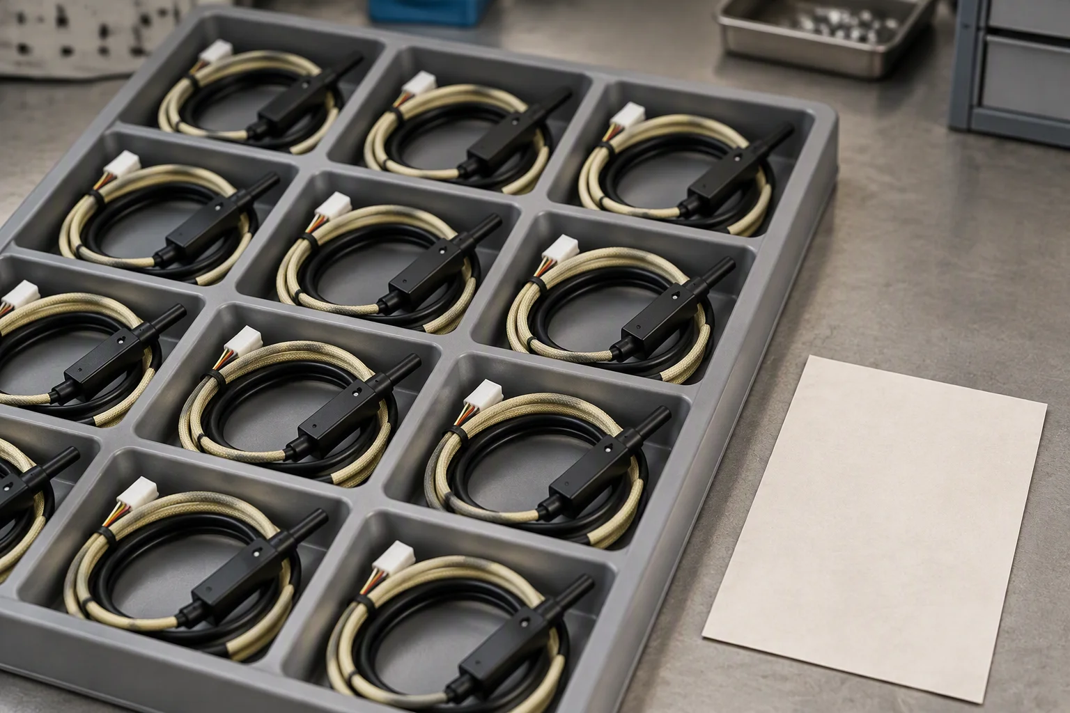
A batch tray of tested point sensors, each in its own compartment with the lead coiled, a paper batch slip beside the tray
FIG 07 ·

After test: one compartment per unit, so a failed channel is found at the tray and not at the panel.

Read next · Capabilities · Projects

04

The faces that decide whether it seals

Section 04 · sealing faces

Three faces decide the seal. They are photographed below at the magnification the machining can be judged at, because the description of a sealing face is the marks on it and not an adjective.
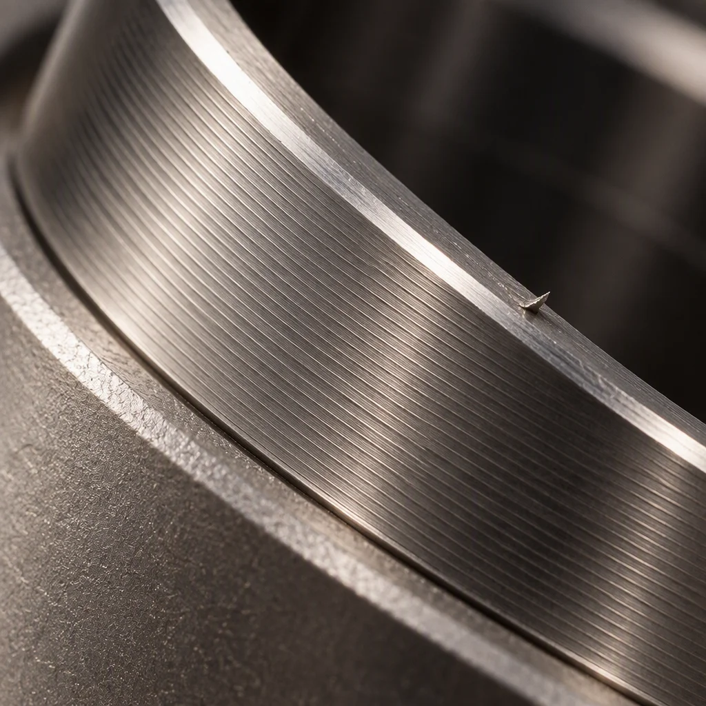
Macro of a machined sealing face on a sensor body, fine concentric turning marks visible across the land with a bright edge at the chamfer
PL 03 ·

The land is turned, not ground. The marks run concentric, so nothing crosses the seal path.
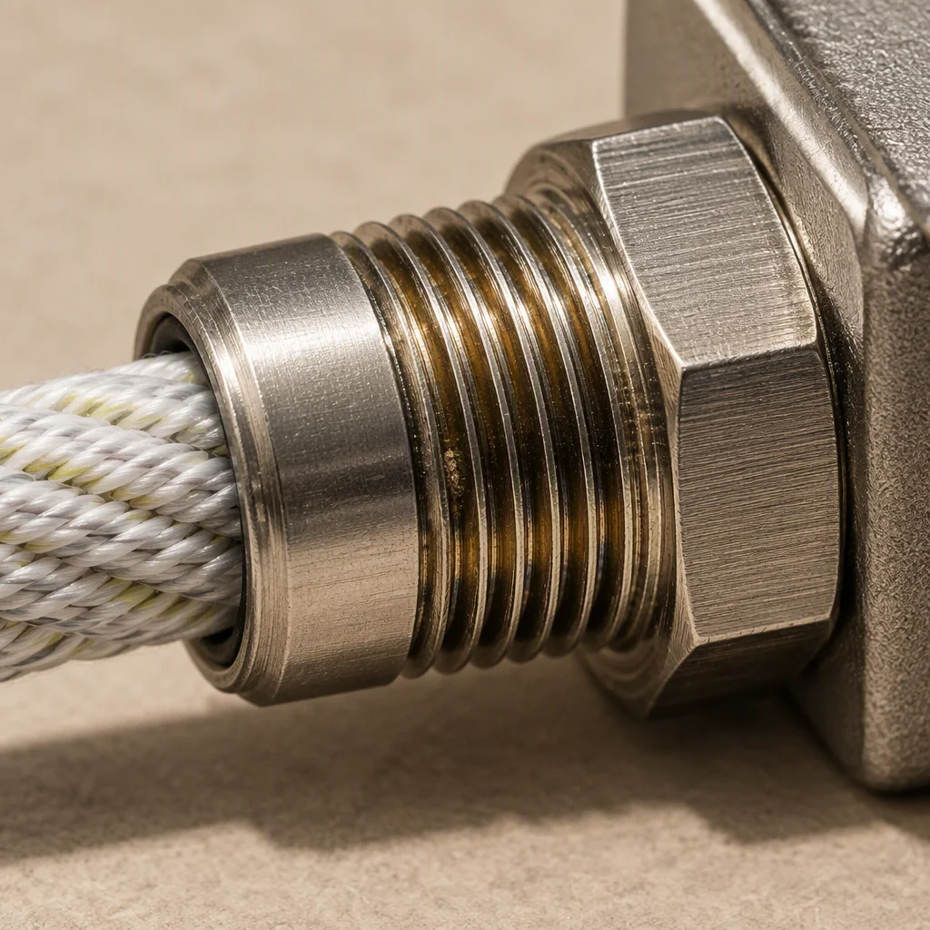
Macro of a threaded cable gland on a sensor body, the thread crests clean and the hex flats showing the broaching marks
PL 04 ·

The gland thread carries no sealant. The seal is the face behind it, and the thread only has to hold it in place.
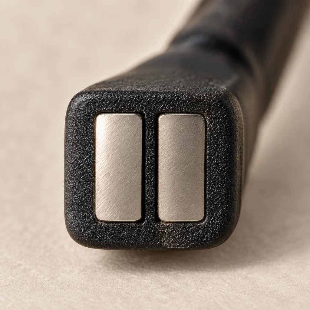
Macro of the two electrodes at the sensing face, set flush in the potting with a clear gap between them and no burr at either edge
PL 05 ·

Flush and deburred. A raised edge holds water back from the gap; a burr bridges it.

Read next · Seal degradation · Supply network

05

What is issued with the batch

Section 05 · documents

Material certificates
EN 10204 3.1 on the metal parts, issued against the batch number on the crate.
Test report
Wet test record for the batch, with the channel time to alarm inside 30 s.
Compliance
CE marking and RoHS on the controller the sensor lands on; REACH on the materials; ISO 9001 on the supplying plant.
Outline drawing
Body outline and lead length, so the tray and the gland can be laid out before the units arrive.
Packing
Leads coiled, one compartment per unit; export crates built to ISPM 15.
Minimum and lead time
MOQ 1 carton; samples 7–10 days; production 25–35 days.
Environment it is fitted in
Unmanned cabinets that swing −20 ~ +55 °C, where a single drip can run for weeks before anyone opens the door.
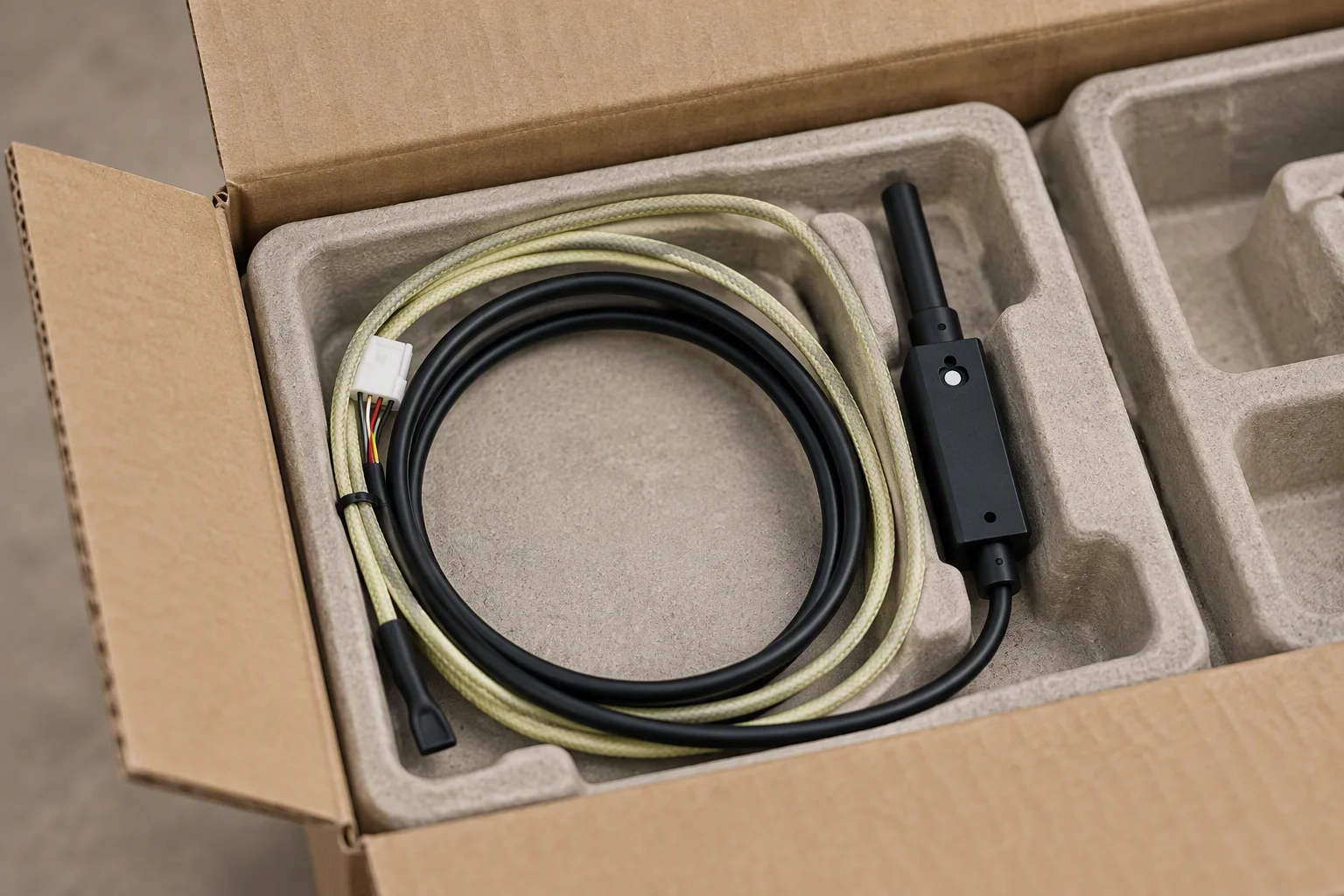
A point sensor sealed in a compartment tray with its coiled lead, the tray sitting in a plain export carton on a packing bench
FIG 08 ·

One compartment per unit: the lead arrives coiled to the length it was ordered at.
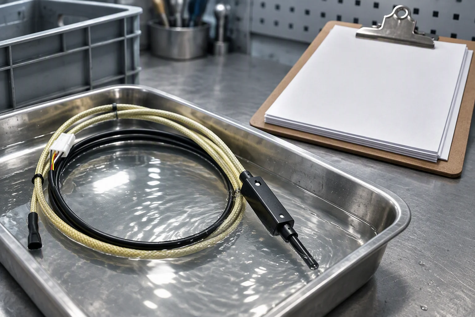
A batch of test data sheets clipped to a board on a bench beside the crate, a wetted sensor still sitting in the test tray
FIG 09 ·

The wet test record is written at the tray and filed before the crate is closed.

Read next · FAQ · Contact

DOCUMENT REQUEST

Request the specification file

Four documents are held for this sheet. One request returns them attached, next business day.

  • Specification sheet body, lead, termination
  • EN 10204 3.1 material certificates metal parts
  • Wet test report batch record
  • Outline drawings body and lead length
The only promise on this page

One business day, with the file attached.

No other commitment is made on this sheet. Price, stock and lead time are not promised here.

If the form cannot send, this address takes the request instead: sales@ems-cool.com
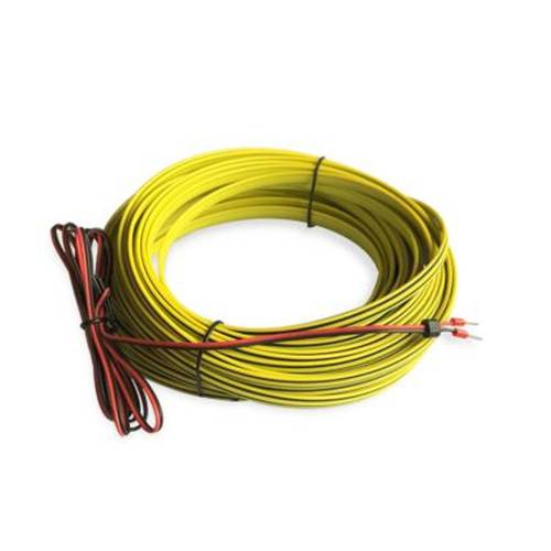
A coil of flat yellow lead cable on a white ground with red and black tail wires ending in crimped ferrules
PL 06 ·

Lead cable, cut to the run, ferrules fitted at the panel end.
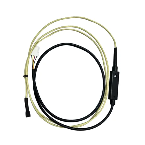
Gold braided sensing rope coiled on a white ground with a black in-line module, a black end cap and a white three-pin housing
PL 07 ·

A rope channel lands on the same pair of terminals as a point sensor.