EMS-Trade
Cooling
Loop consumables

Document ECT-01 · REV C · ISSUED 2026-09 Six lines · 48 sheets

Sheet 23 · Line 01 of six · system

Accessories

End terminations, extension leads and terminal resistors. These parts decide whether a run of sensing rope can be closed at all, and they are ordered with the rope rather than after it.

One business day, with the file attached
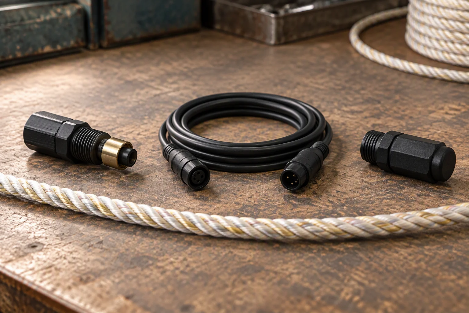
An end termination, a coiled extension lead and a terminal resistor laid out in a row on a bench beside a length of sensing rope
PL 01 ·

Three parts close a run: the termination at the far end, the lead back to the panel, and the resistor that ends the line.

01

Where these parts sit on the loop

Section 01 · position in the loop

The sensing run in the loop: manifold, hose, cold plate, and where the accessory parts sit on the rope The rope runs beside the hose from the manifold to the cold plate. A termination closes the far end of the run, an extension lead closes the gap back to the panel, and a terminal resistor ends the line at the last channel. floor line Manifold Hose Cold plate sensing run 01 termination 02 extension lead Controller 03 end resistor

Key

  1. 01Termination: closes the far end of a run.
  2. 02Extension lead: closes the gap between the run end and the panel.
  3. 03Terminal resistor: ends the line at the last channel.
FIG 01 ·

The rope runs with the hose but lands at the panel. Everything between those two points is on this sheet.

A dripless coupling is the reason this line exists at all. Where a joint is opened for service, the fluid that stays in the open half has to be caught by something, and on a loop running below the floor that something is a sensing run. The accessory set is what lets the run reach the place the fluid would land.
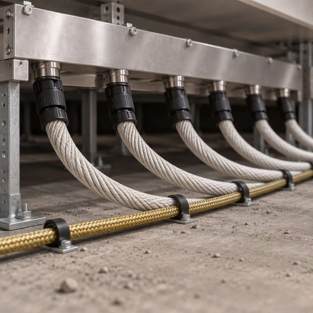
A row manifold above a raised floor with hoses leaving the ports and a sensing rope laid along the same route on the slab below
PL 02 ·

At the manifold: the rope follows the hose run, so the first joint is already covered.
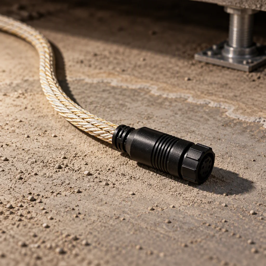
The far end of a sensing run closed with a threaded termination, the jacket trimmed back and the connector sitting flat on the slab
PL 03 ·

At the far end: the termination closes the run. An open end reads as a fault, not as a short run.
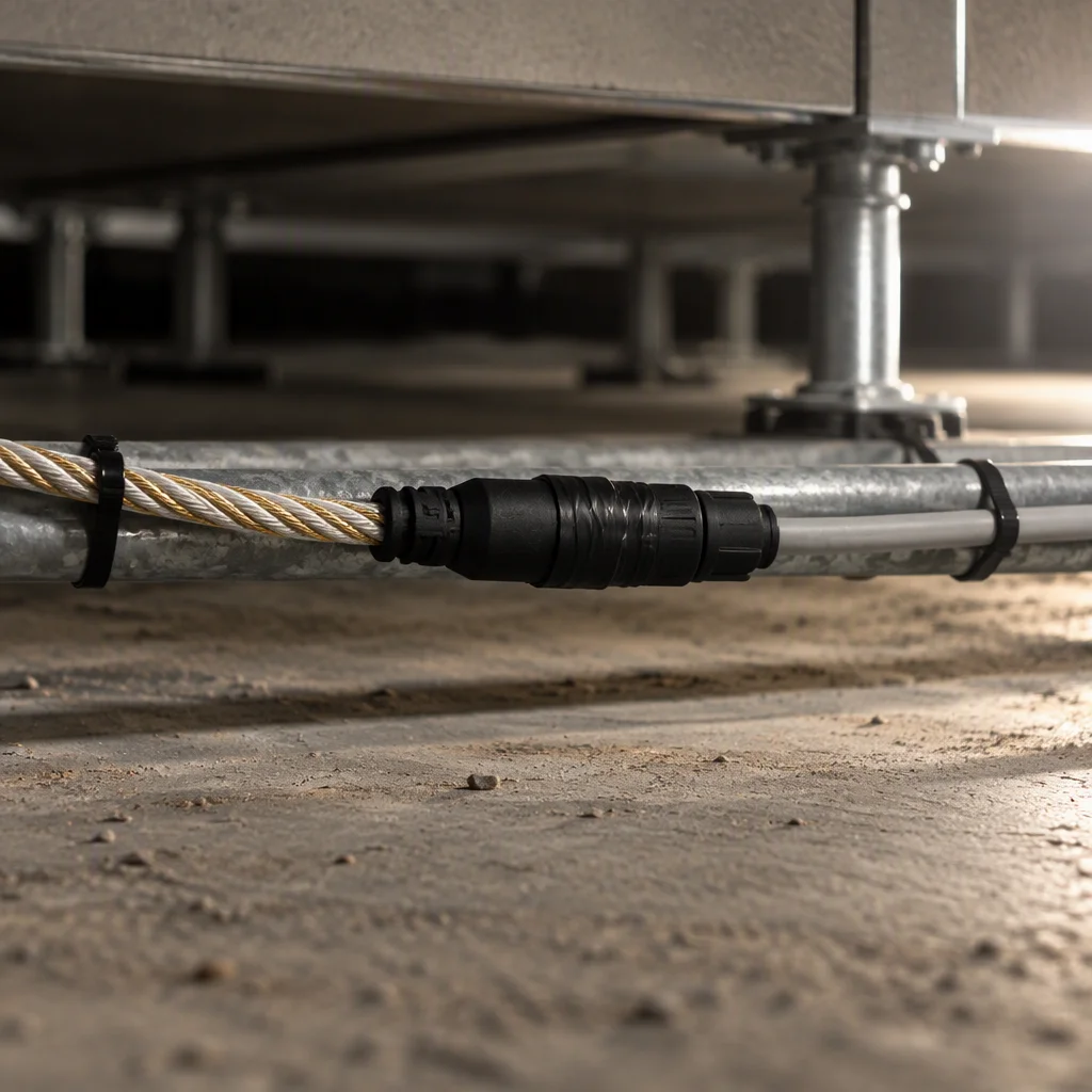
An extension lead jointed to a sensing run on the slab, the two ends mated and taped at the joint with the slack dressed along the pipe
PL 04 ·

Mid-run: the extension lead joins the run to the panel and the slack is dressed, never coiled in the water path.
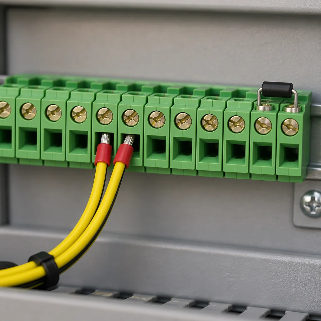
The run landed at the panel on a pair of terminals with a terminal resistor fitted across the last pair to the right
PL 05 ·

At the panel: the pair of terminals, and the resistor that ends the line after the last run.

Read next · Locating sensing rope · Controllers

02

Two interfaces, listed one by one

Section 02 · interface schedule

There is no row on this page that says several options are available. Each part is listed with the interface it presents, because a termination that does not match the jacket it closes is a leak path rather than an accessory.

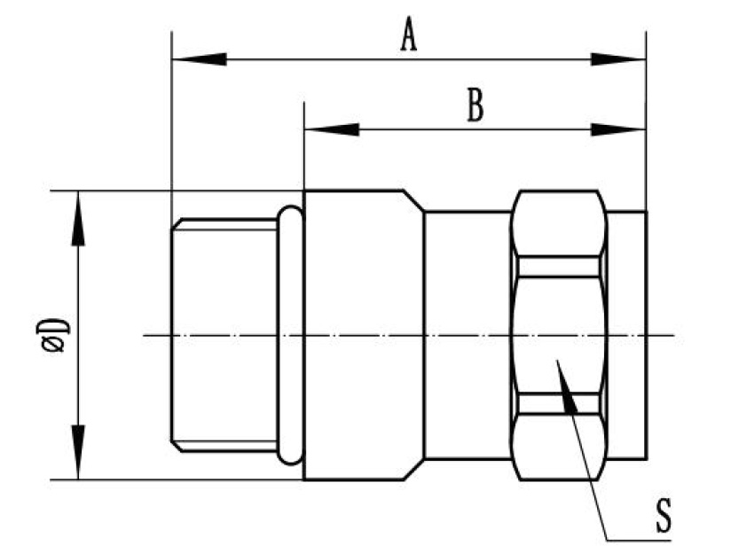
The two drawings below are the interface sheets issued with a quotation. They carry letter callouts rather than dimensions, because the dimension set follows the thread the order names.

Interface schedule · one row per part
Part Presents Takes Called out
End termination A threaded water-tight body over the jacket The trimmed end of a sensing run A · B · D
Extension lead The same threaded body at each end The run end and the panel pair A · B · D · S
Plug housing A keyed housing on a short tail The controller's own header keyed, one way to fit
Terminal resistor A resistor moulded into a termination body The last pair on the strip one per line end
Sealing face A turned land behind the thread The gland nut, on to the land S
Outline drawing of an interface body with A overall length, B thread depth, D diameter and S sealing face called out
FIG 02 ·

The interface sheet: A overall length, B thread depth, D diameter, S the sealing face.
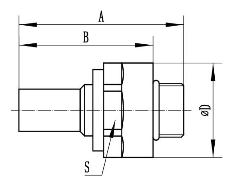
Outline drawing of a second interface body with A, B, D and S called out, the body shorter and the hex across D larger
FIG 03 ·

The second body in the set. The letter set is the same, so one enquiry covers both.

Read next · Fittings & seals · Design guides

03

The fit with what is on either side

Section 03 · assembly

An accessory is only as good as its fit with the two things it sits between: the run it closes and the terminal it lands on. Both fits are dimensional, and both are settled before the rope is ordered.
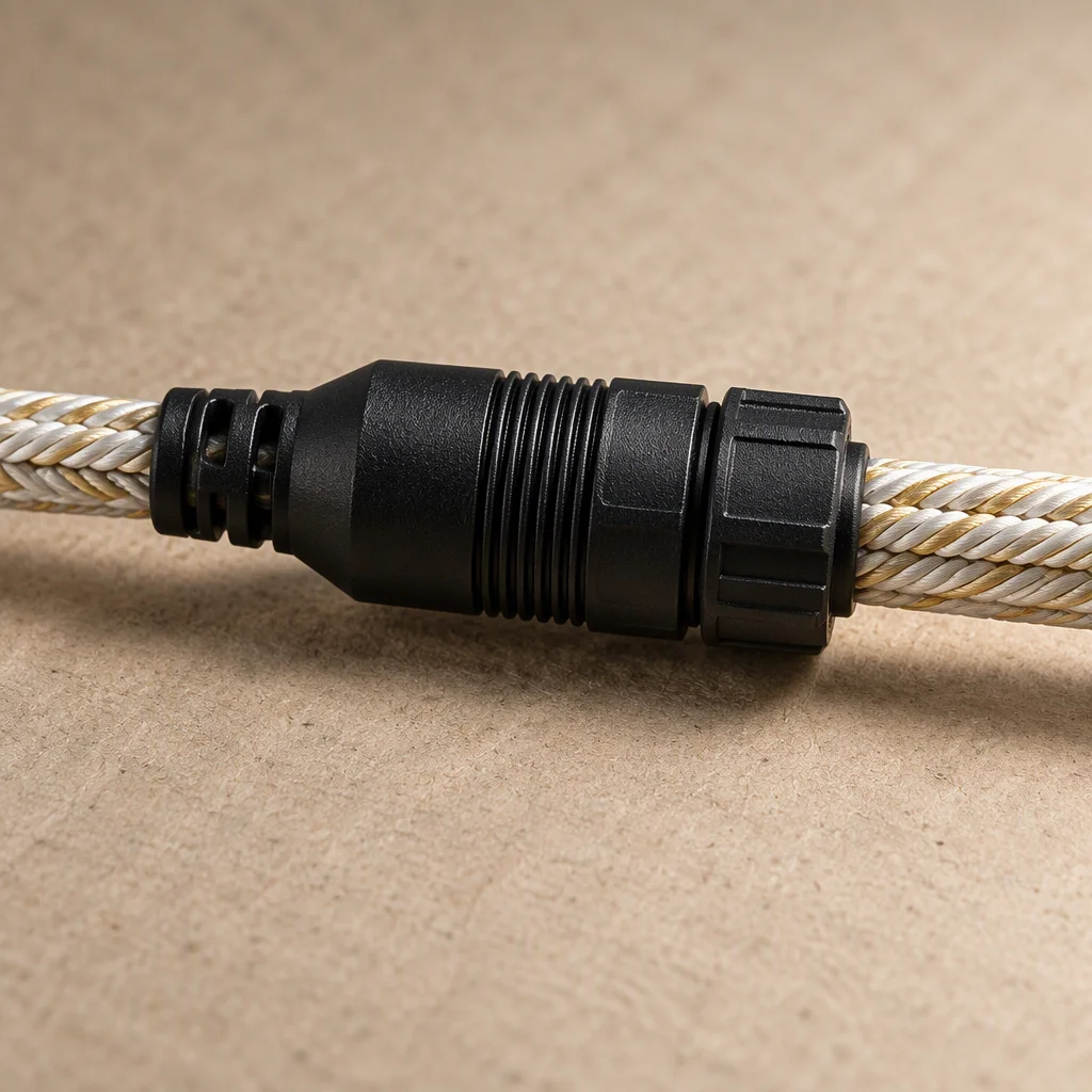
Against the run
The termination is sized to the jacket outside diameter, so the body closes over the weave rather than crushing it. A crushed weave changes the impedance the run reports from.
Run length either side
One channel carries up to 500 m per channel. A termination is fitted at the cut length, so the lead closes whatever gap is left to the panel.
Against the gland
The seal is the turned land behind the thread, not the thread itself. The gland nut only has to hold the body against that land.
Against the panel
One pair of terminals per channel, on a controller carrying 4 · 8 · 16 channels. A rope run and a point sensor land the same way.
At the end of the line
One terminal resistor per line end. Without it the last channel reads as an open circuit rather than a dry run.
From the panel to the report
The channel reaches the BMS over Modbus RTU, a volt-free relay or a 4–20 mA loop, with the alarm inside 30 s.
A termination closed over the woven jacket in close view, the body gripping the weave with no fibres pinched outside the nut
PL 06 ·

The body closed over the weave: no fibre pinched at the nut, no gap at the land.
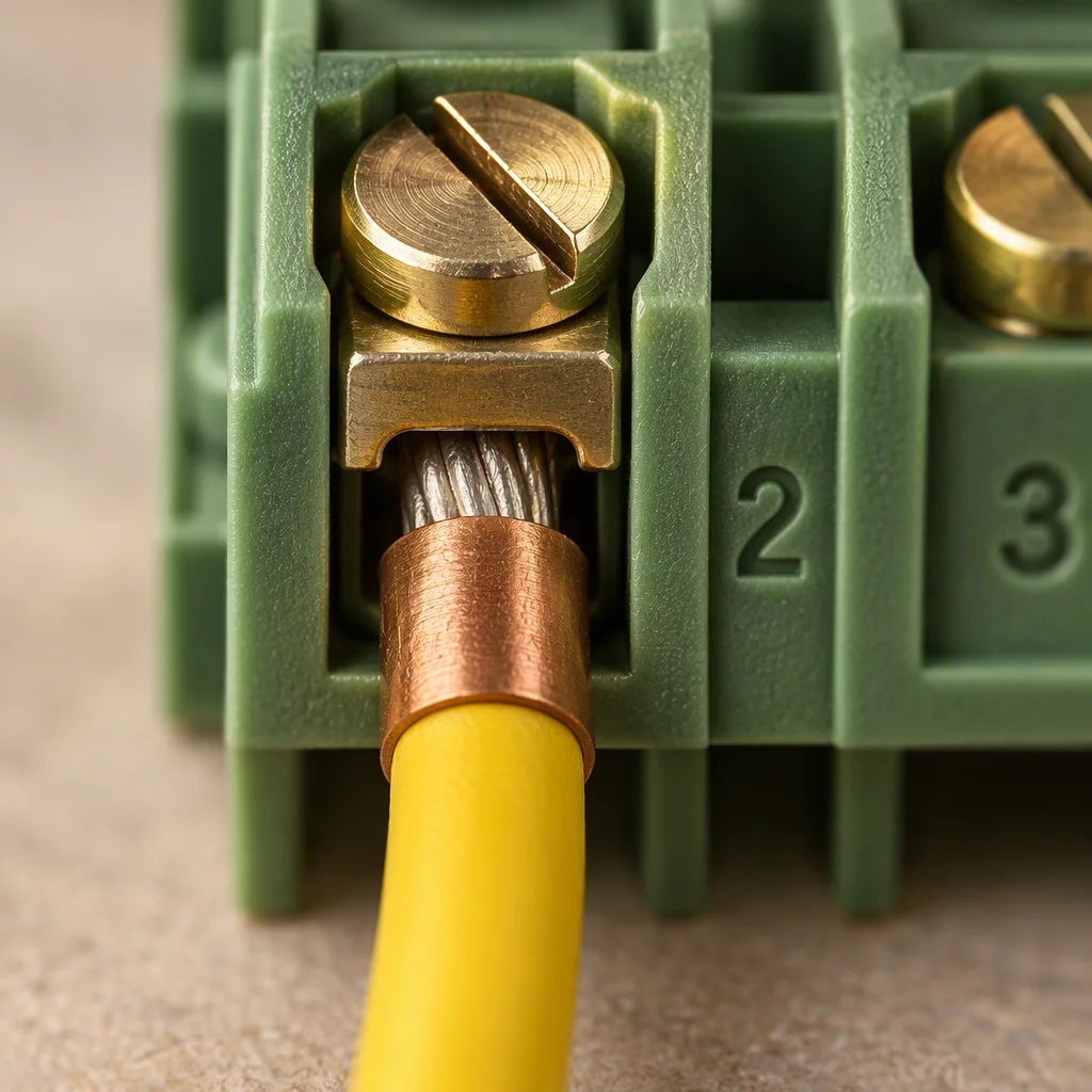
A lead landing on a terminal pair in close view, the ferrule seated under the screw and the pair numbered on the strip beside it
PL 07 ·

A ferrule seated under the screw, not a twisted strand. The pair is numbered, so the channel can be traced.

Read next · Point sensors · Capabilities

04

The parts, one to a cell

Section 04 · the set

Photographed as supplied rather than as drawn. The set is small, and every part on it is ordered with the rope: none of it is available from a panel builder's counter, and none of it is substituted on site.
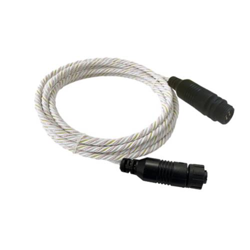
Coiled white twisted-pair sensing cable on a white ground with a black threaded termination at one end and an end cap at the other
01 Threaded termination closes the far end of a run
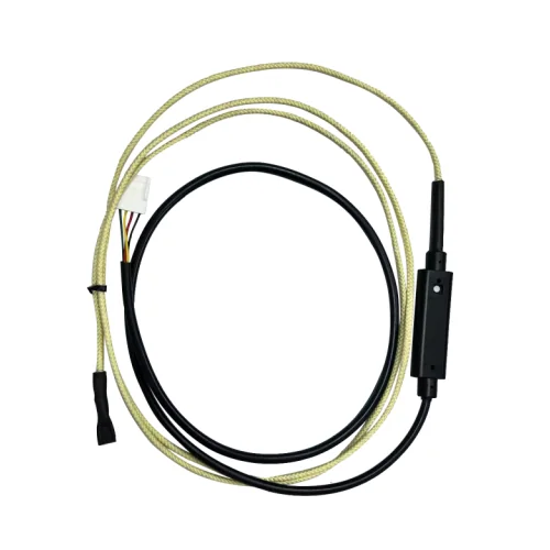
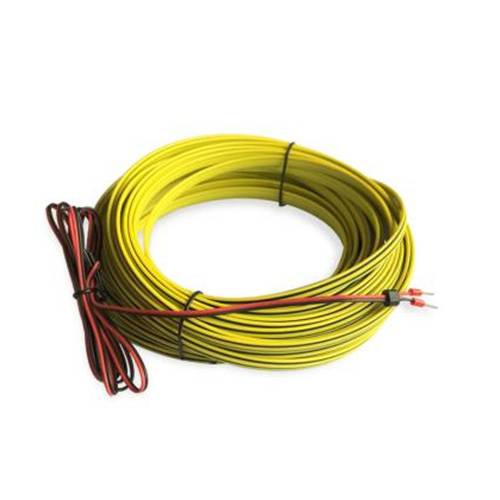
A coil of flat yellow lead cable on a white ground with red and black tail wires ending in crimped ferrules
02 Extension lead closes the gap to the panel
Gold braided sensing rope coiled on a white ground with a black in-line module, a black end cap and a white three-pin plug housing
03 Plug housing keyed to the controller header
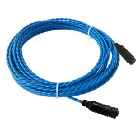
Coiled blue twisted-pair sensing cable on a white ground, held with two white ties and closed with a black connector at each end
04 A closed run terminated both ends, ready to lay

Read next · Quality & inspection · Projects

05

What is issued with the set

Section 05 · documents

Interface sheets
One per part, with the A, B, D and S callouts shown above, so the enclosure and the gland can be laid out from the drawing.
Material certificates
EN 10204 3.1 on the metal bodies, issued against the batch number.
Compliance
CE marking and RoHS on the controller the set lands on; REACH on the materials; ISO 9001 on the supplying plant.
Packing
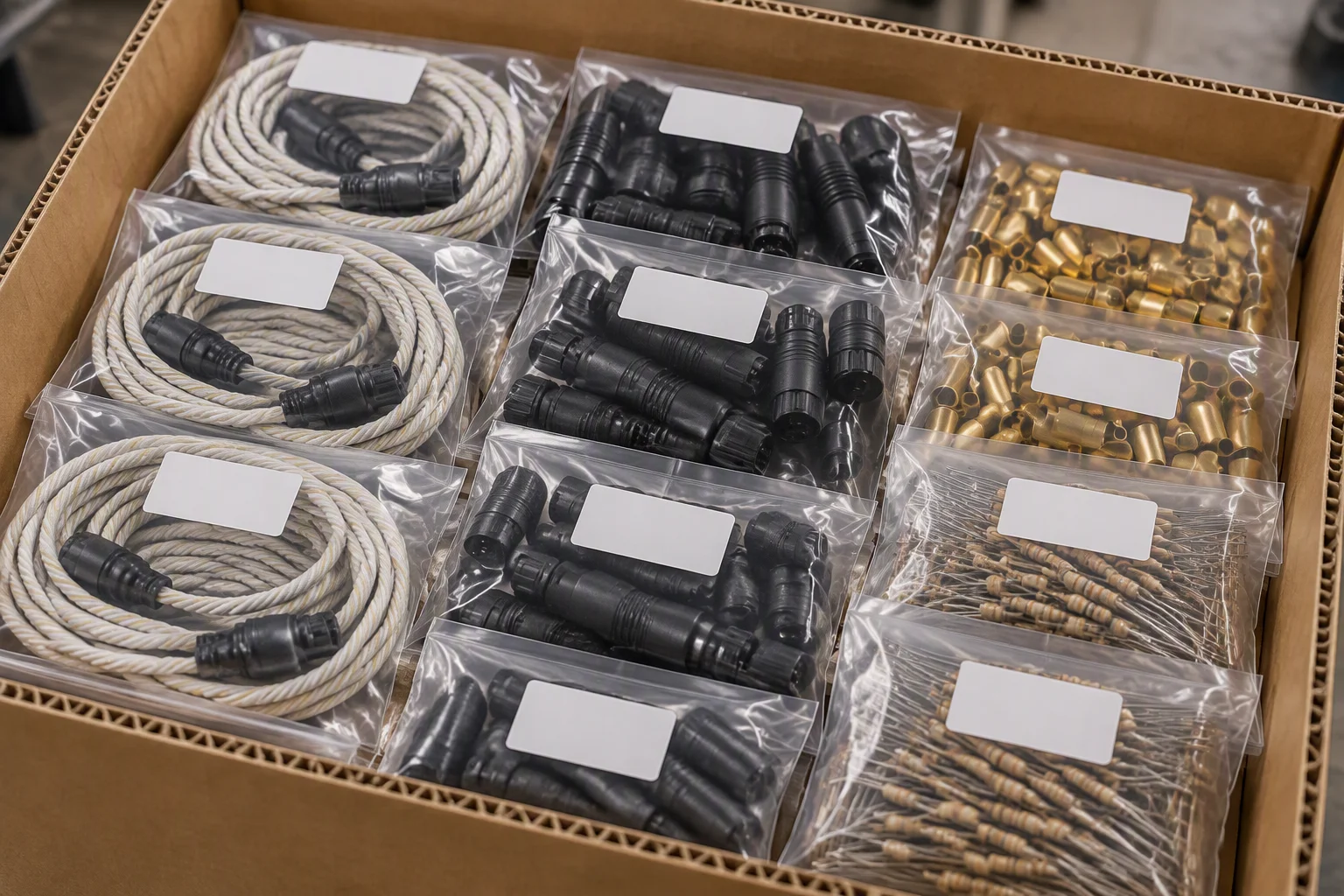
Bodies and leads bagged by part, one bag per part number per crate; export crates to ISPM 15.
Minimum and lead time
MOQ 1 carton, custom lengths from 500 m; samples 7–10 days; production 25–35 days.
Terms
FOB Shenzhen, CIF or DDP. Loops run 5–10 years, so spares are usually ordered with the first crate.
Bags of termination bodies, leads and resistors laid out in an export crate on a packing bench, each bag with its part written on the outside
FIG 04 ·

One bag per part number: a set is picked from the crate without opening anything else.
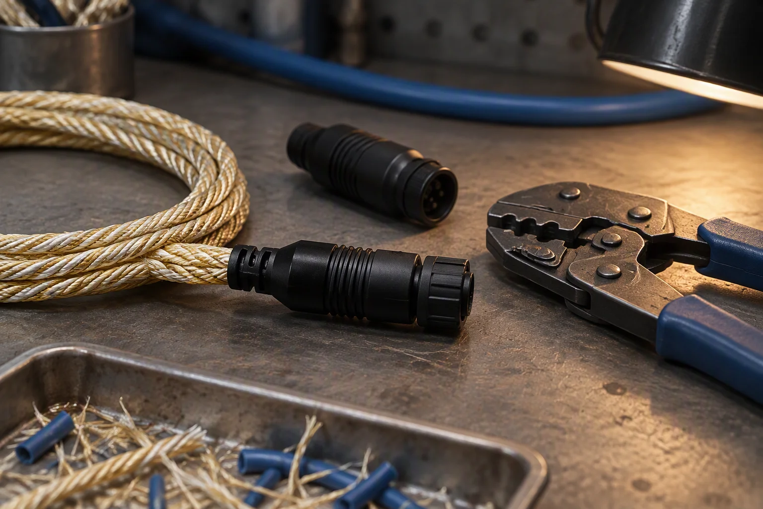
A termination being closed over a rope end on a bench, a crimping tool and a length of lead cable beside it and offcuts in a tray
FIG 05 ·

Closed at the bench. The same two operations are in the outline drawing, so a site can check a delivery against it.

Read next · Supply network · FAQ

DOCUMENT REQUEST

Request the specification file

Four documents are held for this sheet. One request returns them attached, next business day.

  • Specification sheet termination, lead, resistor
  • EN 10204 3.1 material certificates metal bodies
  • Interface sheets A · B · D · S
  • Outline drawings body and lead set
The only promise on this page

One business day, with the file attached.

No other commitment is made on this sheet. Price, stock and lead time are not promised here.

If the form cannot send, this address takes the request instead: sales@ems-cool.com
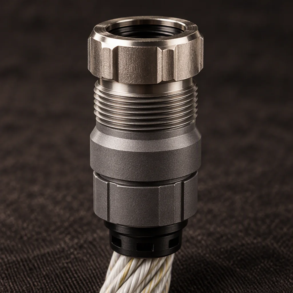
An end termination in close view with its gland nut and the turned land behind the thread, the body grey against a dark ground
PL 08 ·

The termination, drawn at the land and not at the thread.
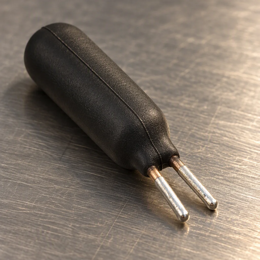
A terminal resistor moulded into a termination body in close view, its two leads trimmed and tinned for the last terminal pair
PL 09 ·

The resistor that ends the line, trimmed to land on the last pair.