EMS-Trade
Cooling
Loop consumables

Document ECT-01 · REV C · ISSUED 2026-09 Six lines · 48 sheets

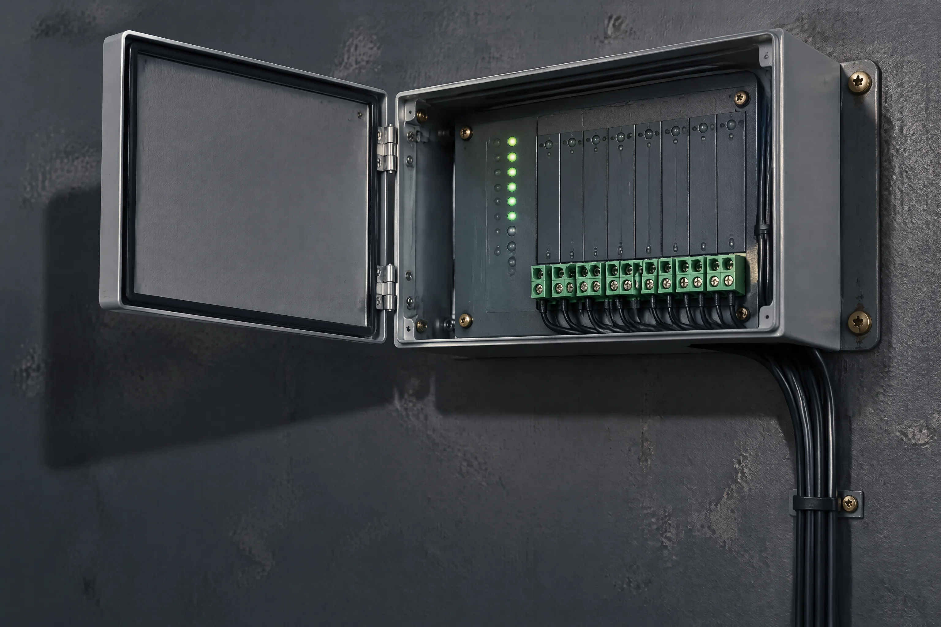
A leak detection controller on a plant room wall, terminal pairs along the lower edge, a column of channel LEDs lit and a hinged cover swung open
Plate 01 · Leak detection · sheet 22 of 48

Controllers

One pair of terminals per channel, and three ways for the alarm to leave the room.

Request the specification file One business day, with the file attached

Channels 4 · 8 · 16Per channel 500 m of ropeAlarm within 30 sOutputs RTU · relay · 4–20 mA

01

Every row here is a condition you can check

Section 01 · boundary conditions

The controller is the cheapest part of the detection chain and the one that decides whether the report is usable. A channel that names an area instead of a position, or a protocol the BMS cannot read, makes the rope and the sensor worth nothing.

So the envelope is read first. Each row below is a condition the unit either meets or does not, and every one of them is checkable against the panel before an order is placed.
Channels
4 · 8 · 16 per controller. Past 16 a second unit starts, and the address the BMS reads changes with it.
What one channel takes
One rope run up to 500 m per channel, or one point sensor. The two are interchangeable on the same pair of terminals.
What arrives at the BMS
A position to 0.1 m from a rope channel, or the state of one place from a point sensor.
Alarm response
30 s including the locating calculation. Inside a hall running an SLA of 99.99% that is 52.6 min a year to spend carefully.
Outputs
Modbus RTU on RS485, a volt-free relay for a local alarm or a PLC, or a 4–20 mA loop for a current input.
Supply
Taken from the panel the unit is mounted in. The wireless gateway carries its own DC socket instead of a pair back to the BMS.
Where it lives
A plant room wall, a panel door, or a floor void beside the run. Cabinet environments swing −20 ~ +55 °C.
How long it serves
Loops run 5–10 years and are re-fitted across generations. The controller outlives the rope it watches.
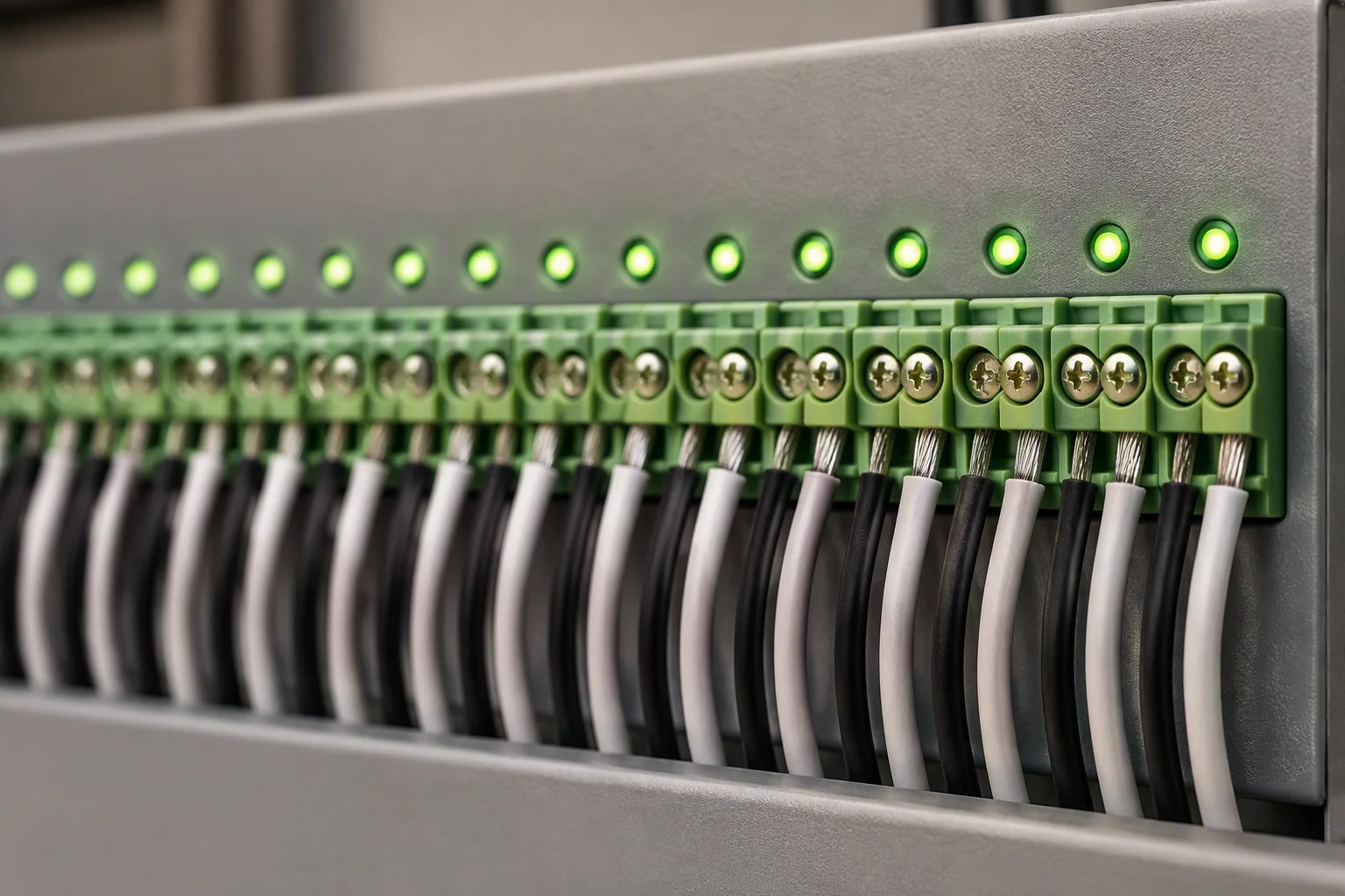
A controller panel with a full row of terminal pairs in use, a lead landed on every channel and the channel LEDs all lit green
FIG 01 ·

Sixteen channels in use: the last pair is still a pair, with its own address.
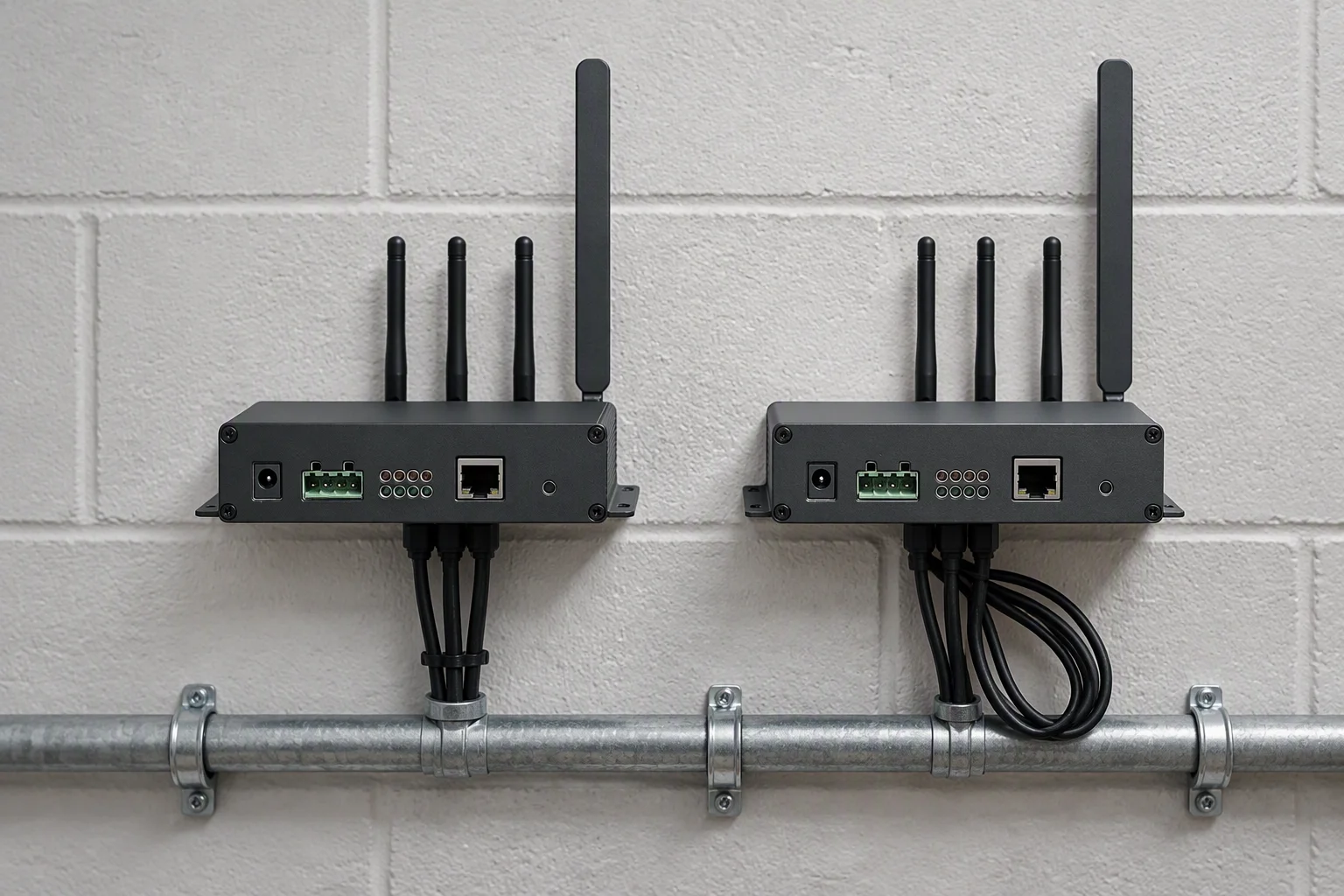
A pair of controllers side by side on a wall, the second one added for a later phase with its lead bundle still separate
FIG 02 ·

Past sixteen, a second unit. Phased fit-outs meet this boundary on the second hall, not the first.

Read next · Locating sensing rope · Accessories

02

What it looks like when the envelope is left

Section 02 · failure forms

These are photographs of the forms the failure actually takes, not drawings of them. A drawing of a wet terminal strip tells a reader nothing they did not already assume; the marks on the strip tell them what coolant does over a season.
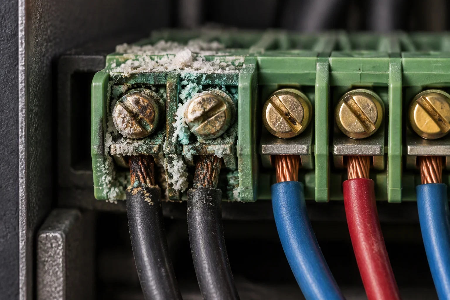
A controller terminal strip after coolant reached it, white and green corrosion salts around two screws and the wire ends blackened
FIG 03 ·

Coolant at the strip. The channel does not fail; it reads high resistance and reports late.
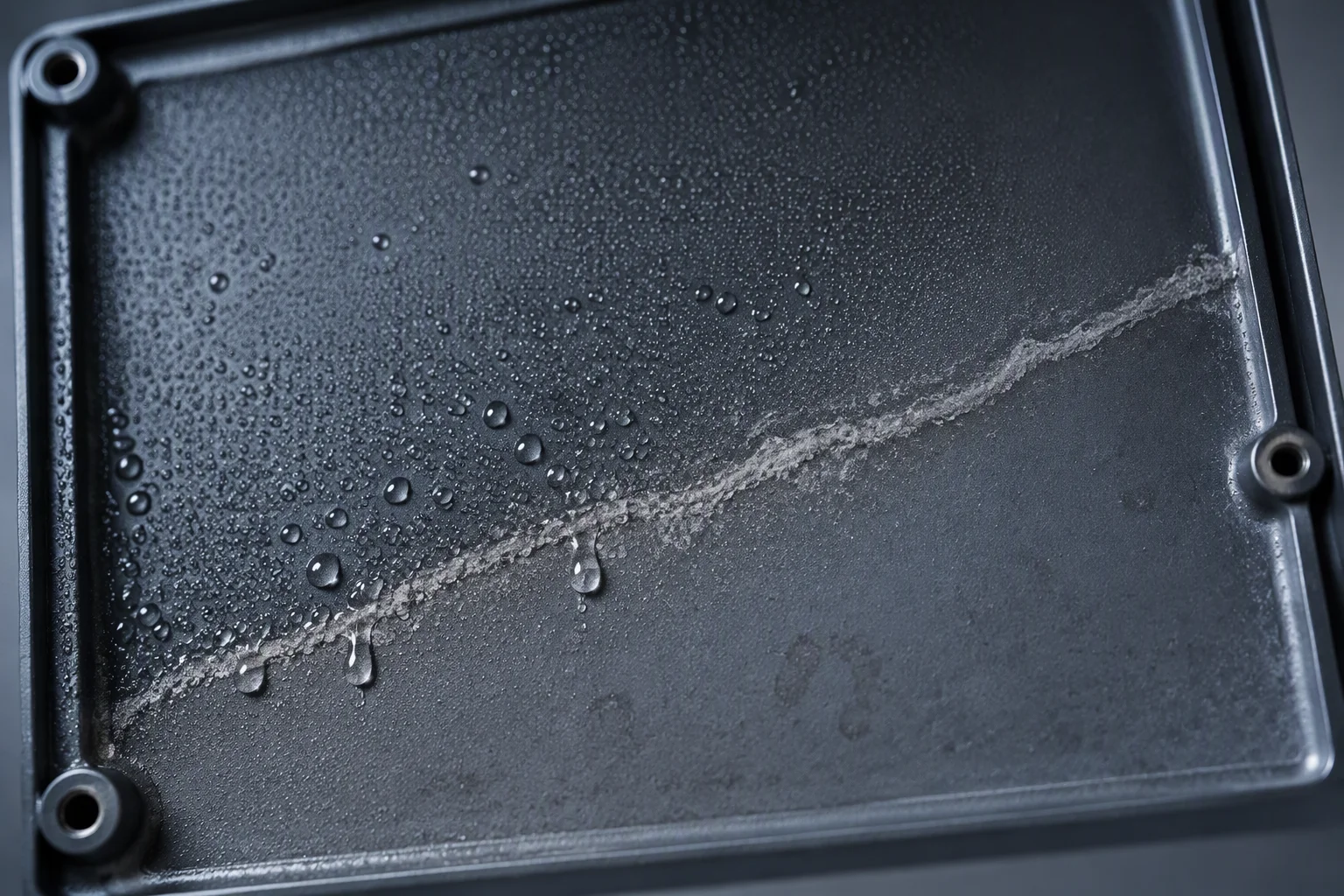
The inside of a controller cover in a cold aisle with a film of condensation across the lower face and a dry tide mark along one edge
FIG 04 ·

Condensation, not a leak. The tide mark shows where the film sat before the hall warmed up.

A controller with one channel held in alarm after its rope was replaced wet, the LED for that channel dark beside lit neighbours
FIG 05 ·

A channel left in alarm after a wet change-out. The rope was replaced and the channel was not cleared.

100 kW+ Per AI training rack Up from 10–15 kW. More coolant in the loop, so a leak releases more water
99.99% SLA in colocation 52.6 min a year. One wet joint can spend the whole allowance
30 s Alarm response Including the locating calculation, to the address on the floor plan
5–10 years Loop life Across generations of hardware on the same controller

Read next · Hyperscale & AI · Colocation

03

Media against materials, two axes

Section 03 · compatibility

The matrix is read across a coolant and down a material. Nothing in it is a temperature rating: it answers only whether the wetted parts survive the fluid, and the answer changes with what the fluid carries.

Two entries drive most of the damage. Metal ions released into a deionised loop are the reason stainless and fluoropolymer are preferred at the wetted end, and an elastomer is attacked by the same fluid it seals.

Wetted parts against coolant · assessed, not rated
Coolant EPDM 316L Brass PA PFA
Water-based coolant yes yes check yes yes
Glycol-based coolant check yes no check yes
Deionised water yes yes no check yes
Glycol concentration off-spec no yes no no yes
yes · in service, unchanged check · survives, but confirm the grade with the fluid supplier no · do not put it in the loop

A glycol mix that drifts off-spec swells or shrinks an elastomer within weeks, so the concentration is a compatibility input and not only a freeze point.
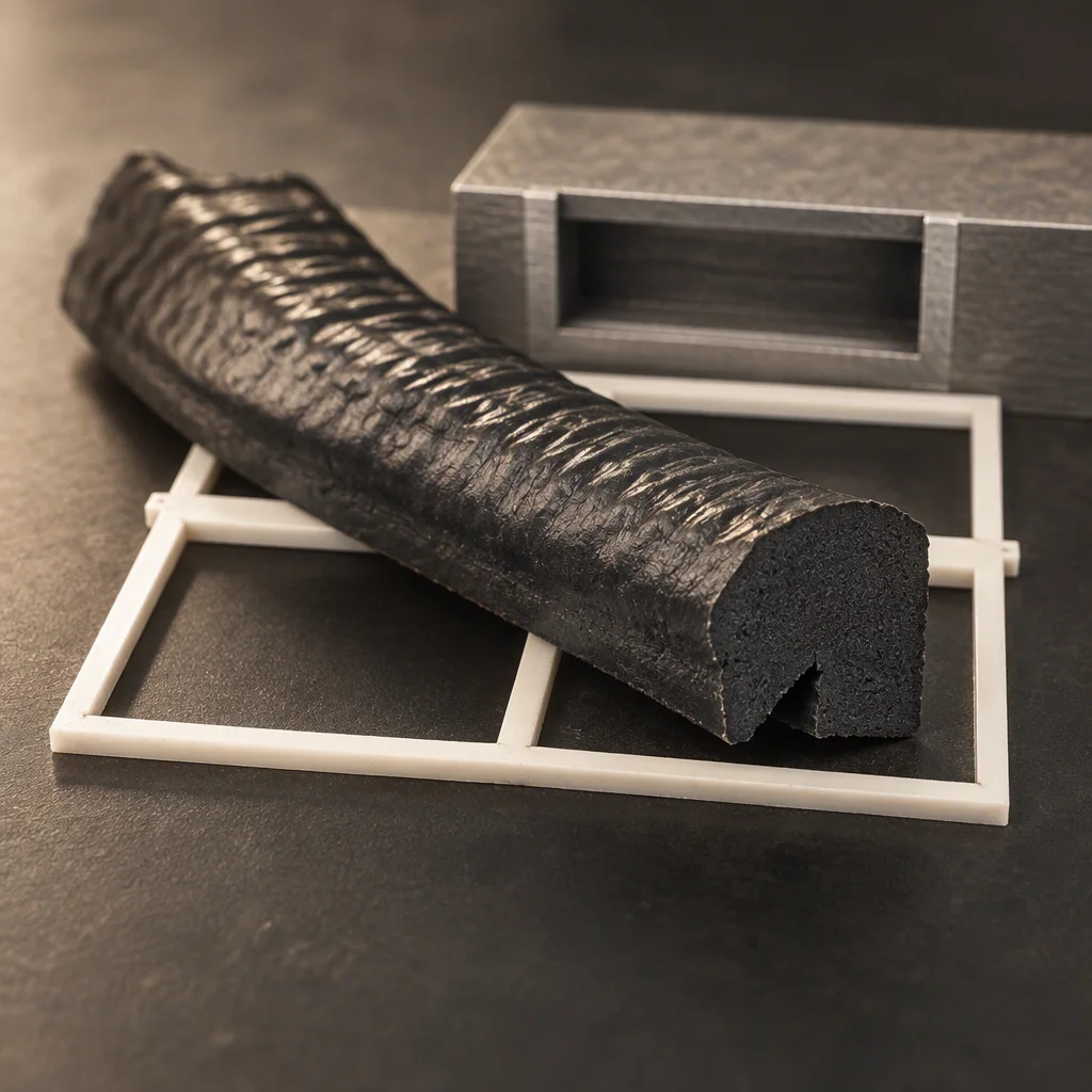
Macro of an elastomer seal after glycol exposure, the surface rippled and the section swollen beyond its original profile
PL 01 ·

Swollen, not worn: the seal grew and the gland it sat in did not.
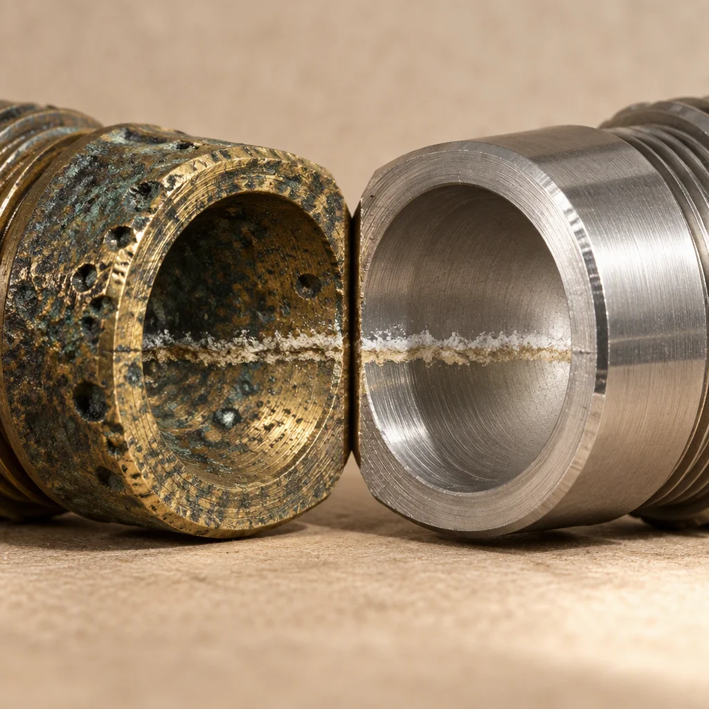
Macro of a stainless wetted face next to a brass one, the brass pitted and dull and the stainless face still bright
PL 02 ·

Pitting on the brass side of the same loop. The metal went into the fluid and then into the loop.
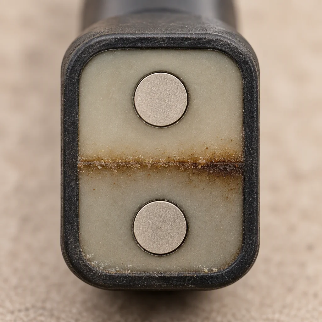
Macro of a point sensor face after a season in a coolant loop, the potting stained along a line where fluid sat against the body
PL 03 ·

A season against the same fluid leaves a line on the potting. It is the cheapest compatibility test there is.

Read next · Fittings & seals · Fluid quality monitoring

04

The three places it ends up

Section 04 · installed form

Where the unit is mounted decides how long the leads run and who is standing in front of it when it alarms. There are three forms in service, and the third one is the one that gets forgotten at handover.
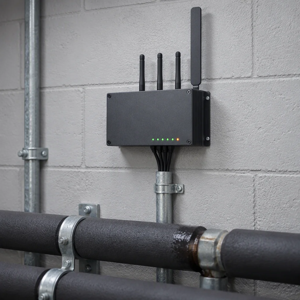
A controller fixed to a plant room wall above a pipe run, its cover closed with the channel LEDs visible along the front edge
PL 04 ·

Plant room wall: the version a round walks past, so the LED column is worth having.
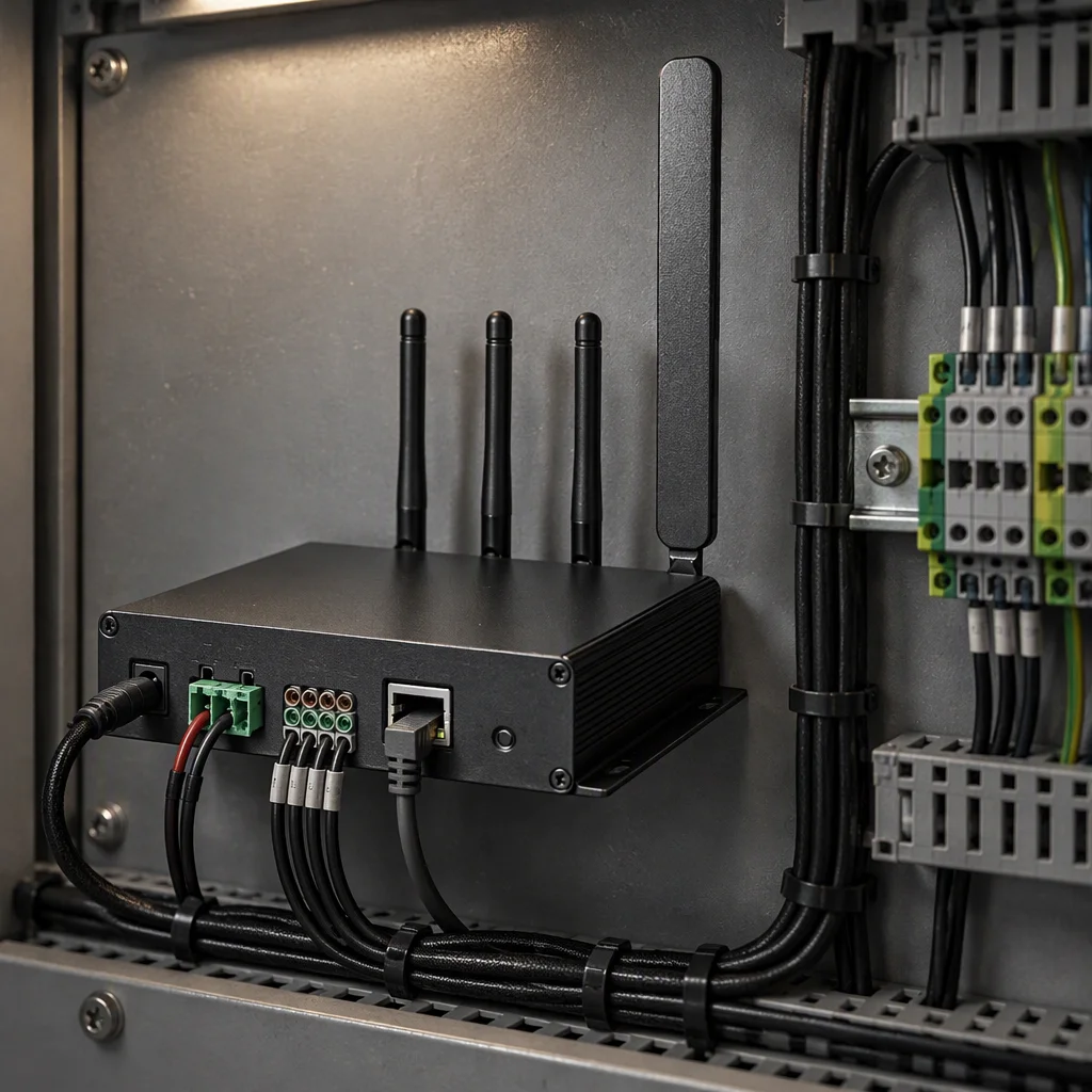
A controller mounted inside a control panel beside terminal blocks and a DIN rail, its cover open with the wiring loom dressed to the side
PL 05 ·

Panel door: reached only by the electrical contractor, which is the right form when the BMS is the only reader.
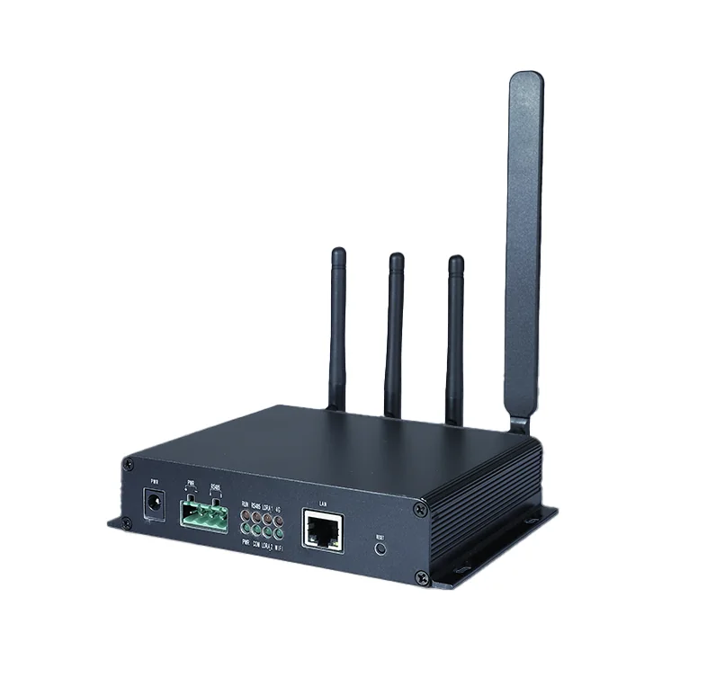
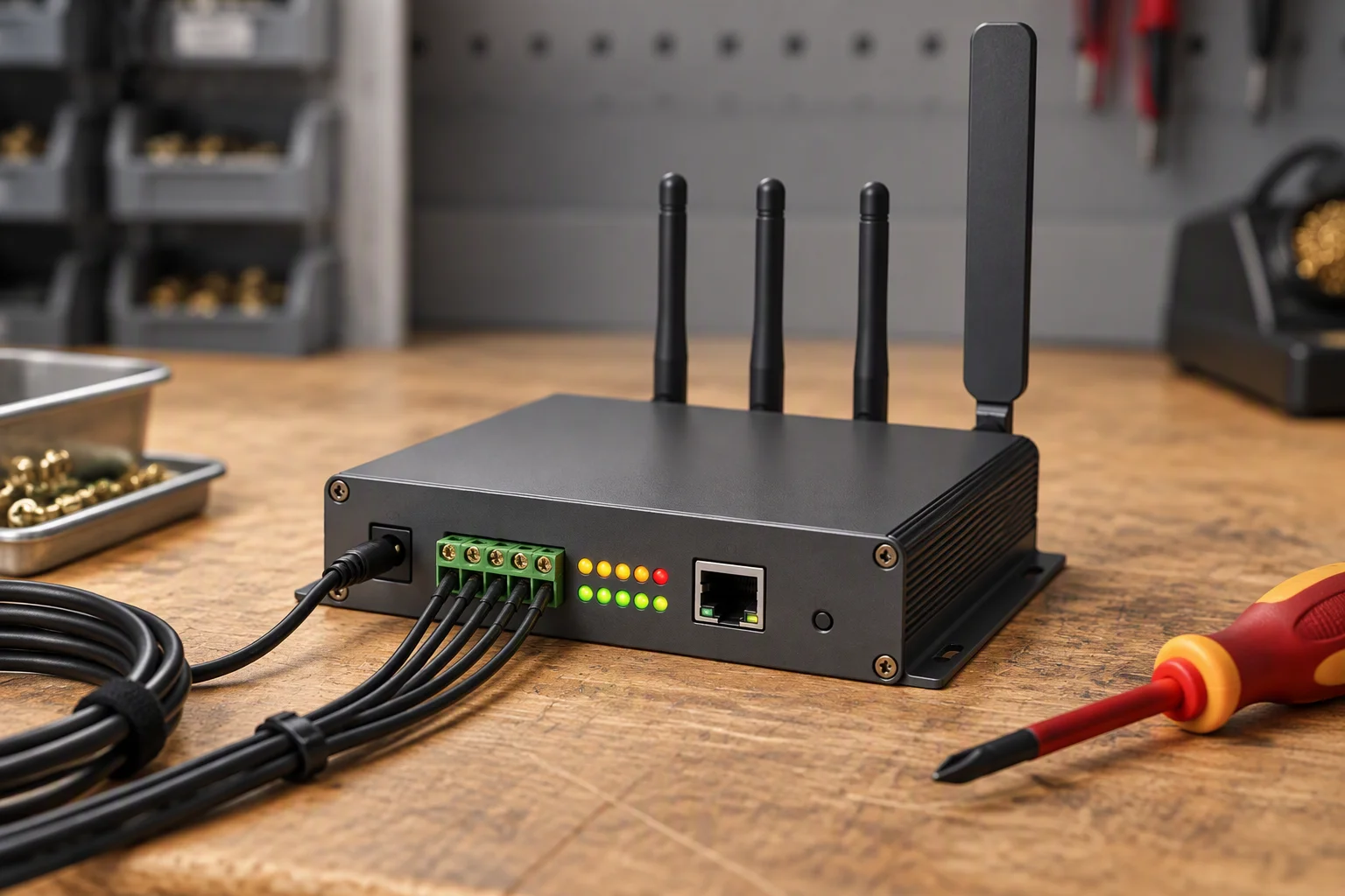
Black finned gateway with four antennas, a green screw terminal block, a network port and a DC power socket on the front panel
PL 06 ·

Floor void, no spare pair: RS485 in, wireless out. The form forgotten at handover is usually this one.

Plant room wall
A pair per channel back to the unit, and a Modbus RTU pair onwards to the BMS.
Control panel
Channels wired to the panel's own terminals; the report leaves on a 4–20 mA loop or a volt-free relay.
Floor void, wireless
No pair to the BMS is needed, but the unit needs power and a place above the water line.
In all three
Leads are landed in pairs and numbered along the strip, so a channel can be traced from the panel to a joint without opening the floor.

Read next · Projects · Industries

05

What is issued with the unit

Section 05 · documents

Specification sheet
Channel count, the three output paths and the terminal arrangement, one page per version.
Compliance
CE marking and RoHS on the unit; REACH on the materials; ISO 9001 on the supplying plant.
Material certificates
EN 10204 3.1 on the metal wetted parts, traceable to the batch.
Test report
Channel-by-channel wet test on the delivered unit, timed against the 30 s alarm.
Packing and terms
Export crates to ISPM 15; MOQ 1 carton; samples 7–10 days; production 25–35 days; FOB Shenzhen.
A controller on a test bench with a lead landed on each channel, the channel LEDs lit one after another as the tester works along the strip
FIG 06 ·

Channel by channel: every pair is landed and timed before the unit is packed.
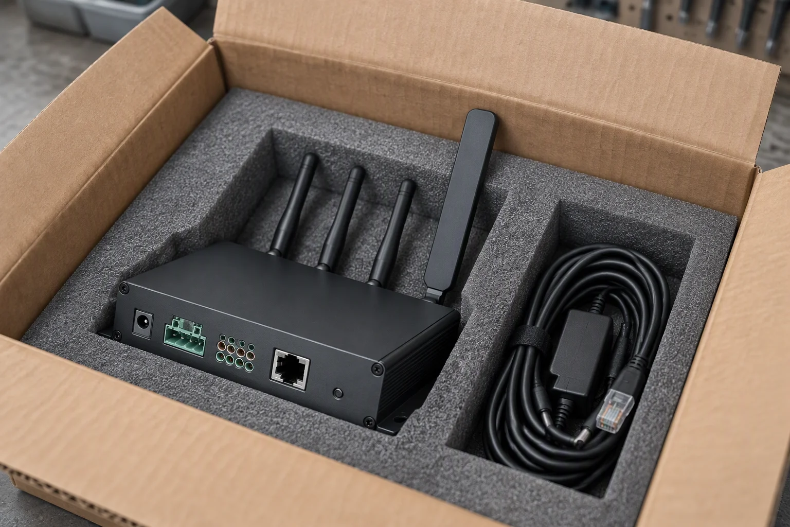
A controller in a foam-lined export carton on a packing bench with its lead set coiled beside it and the carton flaps still open
FIG 07 ·

In the crate: the unit, the lead set and the paper the order named, in one carton.

Read next · Quality & inspection · Contact

DOCUMENT REQUEST

Request the specification file

Four documents are held for this sheet. One request returns them attached, next business day.

  • Specification sheet channel count and outputs
  • EN 10204 3.1 material certificates metal wetted parts
  • Channel wet test report delivered unit
  • Outline drawings enclosure and terminals
The only promise on this page

One business day, with the file attached.

No other commitment is made on this sheet. Price, stock and lead time are not promised here.

If the form cannot send, this address takes the request instead: sales@ems-cool.com
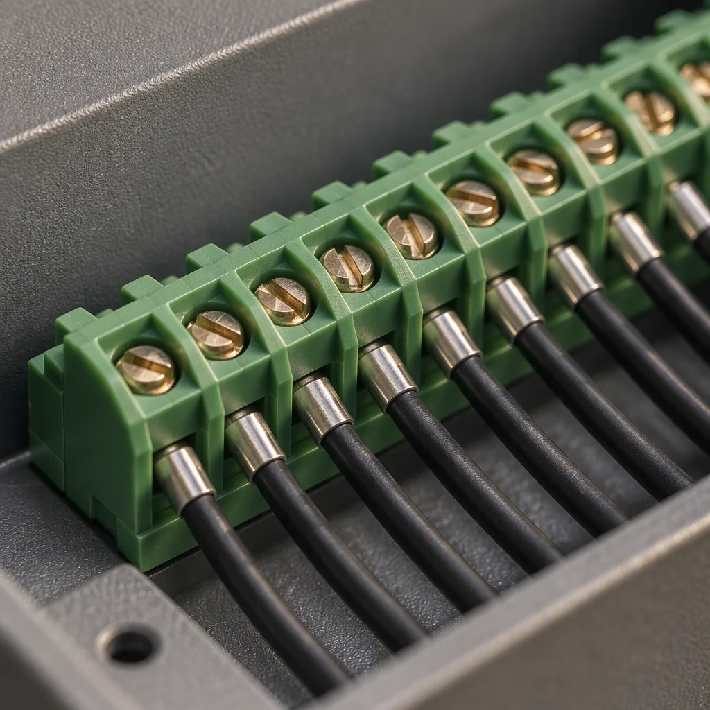
Controller terminals in close view, one numbered pair after another along the strip with a single lead landed on each
PL 07 ·

One pair per channel, numbered along the strip.
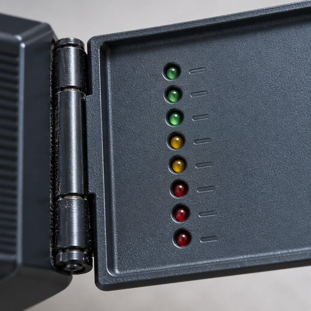
A controller cover swung open on its hinge in close view, the LED column and the channel labelling visible on the inner face
PL 08 ·

Cover open: the LED column stays readable without lifting a lead.