EMS-Trade
Cooling
Loop consumables

Document ECT-01 · REV C · ISSUED 2026-09 Six lines · 48 sheets

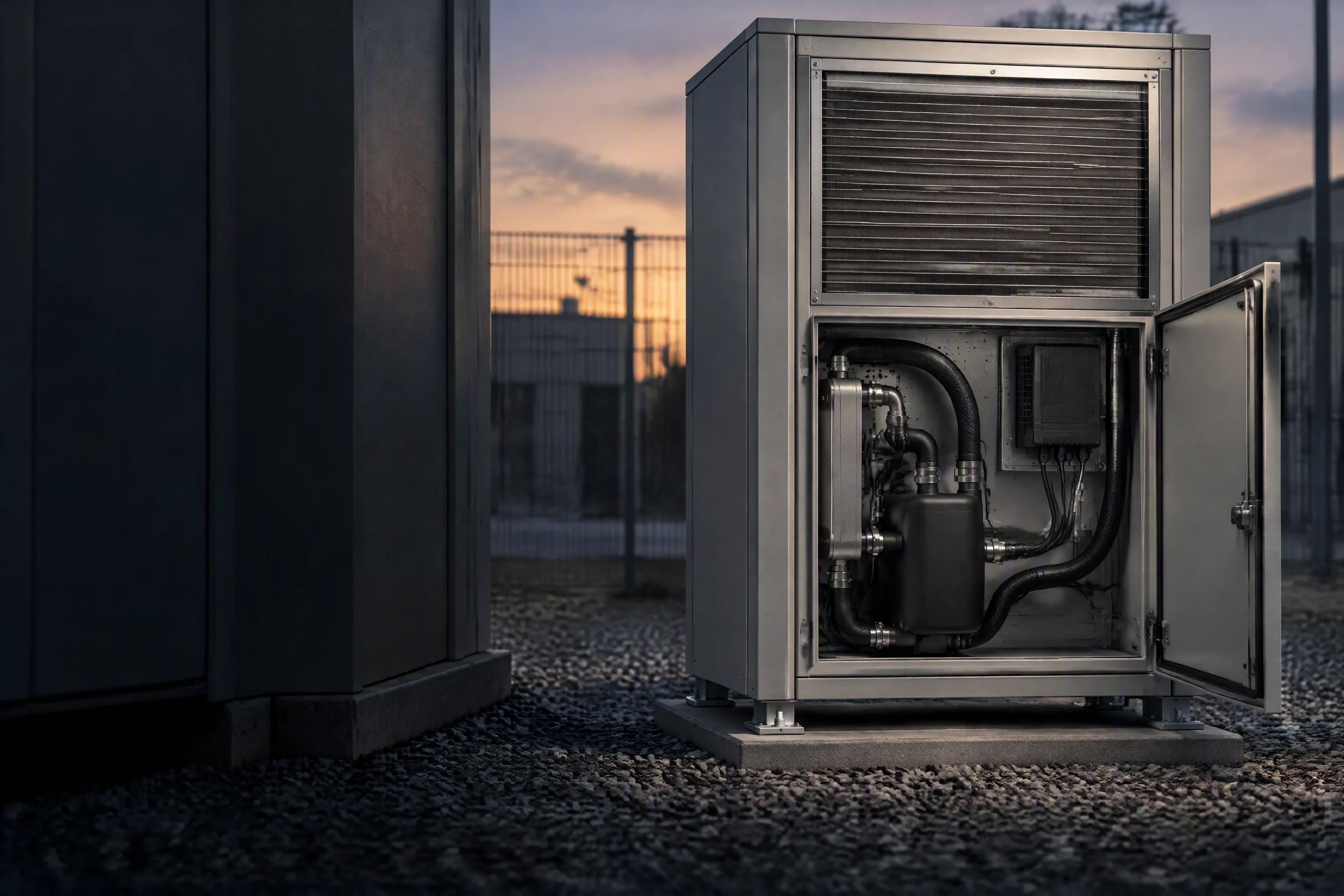
An unattended outdoor cabinet at dusk: a finned heat exchanger on the upper door, the service panel open on a small liquid loop with a controller and two hoses inside, gravel at its feet and no one on site
Sheet 41 · Edge & telecom · the unattended cabinet

Nobody is on site when the loop starts to weep
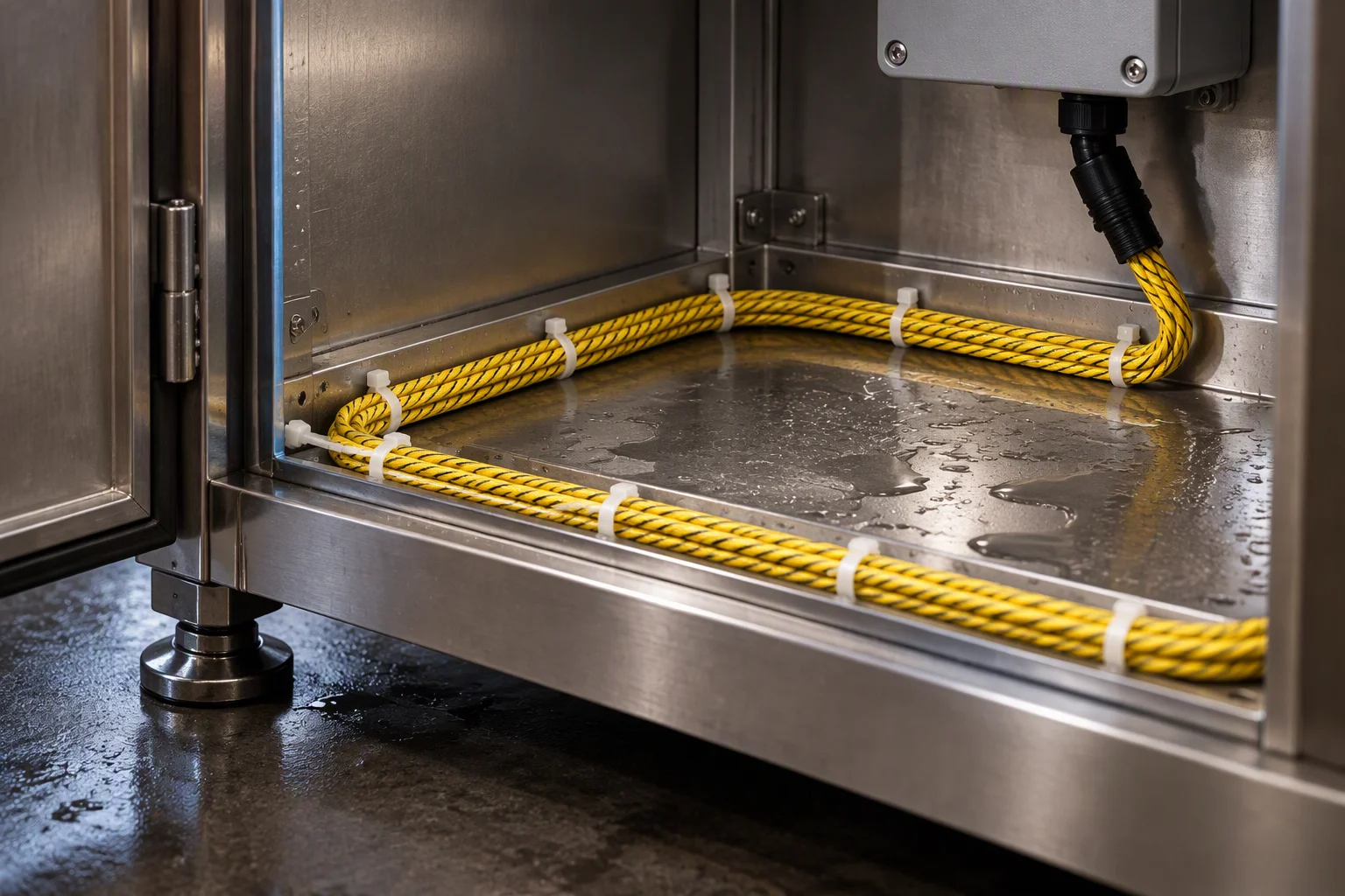
The base pan inside an open cabinet with a braided sensing cable run around its edge under the tie-downs
SP 2 ·
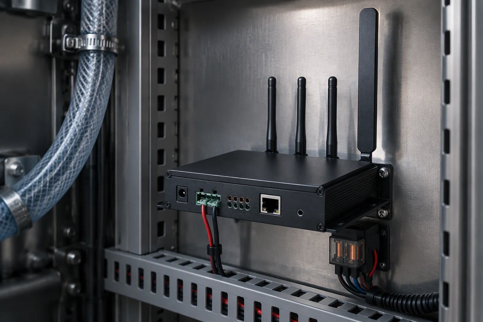
A black controller on the inside wall of a sealed cabinet with a terminal block along its lower edge and a small relay beside it
SP 3 ·
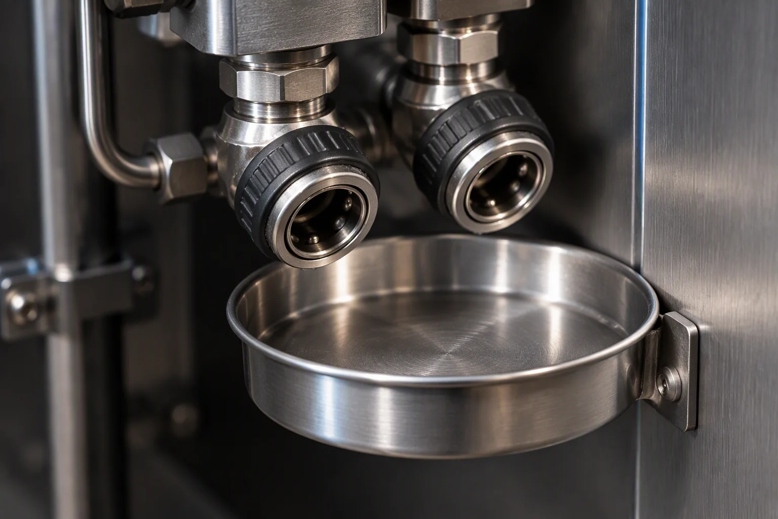
A drip tray under a quick disconnect pair inside a cabinet, the tray dry and the lock collar facing out
SP 4 ·
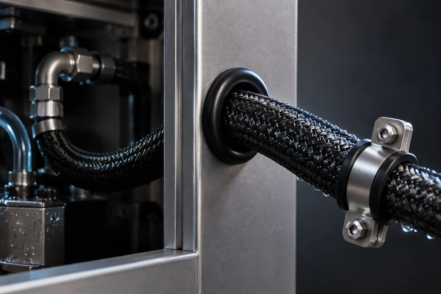
A braided hose passing through a grommeted opening in a cabinet wall, clamped once outside
SP 5 ·
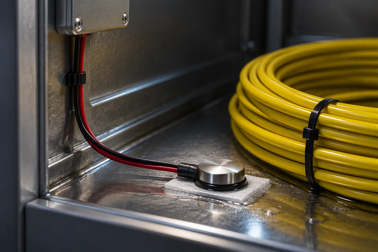
A point sensor fixed to the tray under a coil inside a cabinet, its lead running up the wall to a terminal box
SP 6 ·

Ambient band −20 to +55 °CPer channel 500 mAlarm inside 30 sLocal output dry contact

A cabinet on a kerb is inspected on a schedule, not on a reading. Everything this sheet specifies is chosen so that the loop reports its own condition between two visits, and reports it where it stands.

One business day, with the file attached

01

Four facts a cabinet on a kerb imposes

Pain statement · the conditions this industry actually runs under

Unattended
There is no round and no one on call at the cabinet. Whatever happens between two maintenance visits happens unobserved, all the way to the end.
Ambient
A cabinet on a pole or a kerb sees −20 to +55 °C over a year. The elastomer, the liner and the electronics all have to be specified for that band, not for a hall.
Local alarm
When the site loses power and backhaul together, an alarm that only exists upstream does not exist. Detection has to close a dry contact where it stands.
Weeks
A slow weep is measured in weeks. By the time anyone opens the door, the fluid has dried, the reading has moved and nothing on site is fresh enough to be evidence.
02

What an unattended loop does between two visits
Pain plates · the site in winter, the dried mark, and the only reading in the box

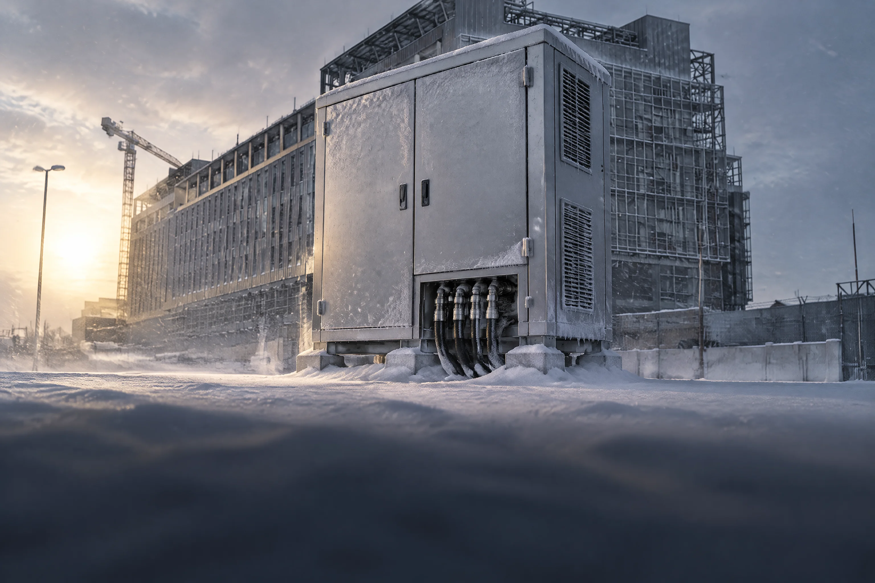
The front of an outdoor cabinet on a winter morning, frost on the door and snow banked against its base, with a hose visible below the service panel and no tracks anywhere on the ground
FIG 1 · ambient band

−20 to +55 °C over a year, on the same elastomer, the same liner and the same sensing cable. Nothing on this sheet is specified for a hall.
−20 °CCold end of the band
+55 °CHot end of the band
30 sFrom water to a closed contact
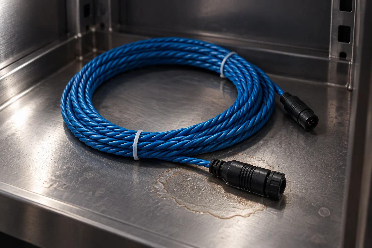
A dried tide mark on the floor of a cabinet, spreading from below a coupling and leaving a ring at its edge, with the sensing cable still tied to the tray beside it
FIG 2 ·

Weeks after the event the mark is the evidence, and it is the only one left on site.
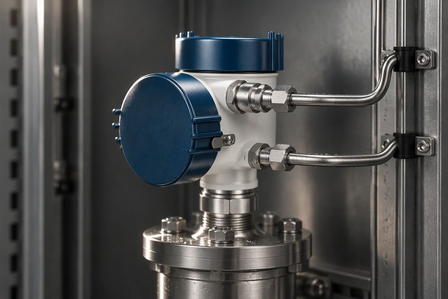
A differential pressure transmitter on a filter housing inside a narrow cabinet, its two impulse tubes run along the cabinet wall
FIG 3 ·

Filter loading is the one reading the box can produce on its own, all year, without a visitor.

02

What we will put in writing for an unattended cabinet

Schedule T · acceptance conditions for the loop, not for the CDU

Schedule T · the conditions this industry is quoted on
No Condition Value Unit Basis
01 Ambient bandSeals, liner and sensing cable −20 to +55 °C Specified for a cabinet on a kerb, not for a hall
02 Detection length per channelLocating sensing rope 500 m A whole site run on one channel, position not zone
03 Leak location resolutionLocating sensing rope 0.1 m Which cabinet, not which site
04 Alarm responseController output 30 s Including the locating calculation, not just contact closure
05 Local annunciationOn loss of power and backhaul 1 dry contact The alarm exists where the cabinet stands, not only upstream
06 Hose temperature bandWater-based coolant −40 to +99 °C The band claimed for this application, wider than the cabinet band
07 Hose working pressureDASH −4 to −10 1.38 MPa About 200 psi, burst above 5.5 MPa
08 Cartridge absolute ratingFilter in the cabinet 1 µm Grades from 0.05 to 100 µm on one housing
09 Cleanliness at chargeLoop fluid 17/15/12 ISO 4406 Sampled at the cabinet, before the loop is closed
10 Shell design pressure304 and 316L 1.0 MPa Hydrostatic proof per batch

The value column is the figure we will be held to, and every figure in it is one this loop is bought against. Where a tolerance is not published, the cell stays empty rather than carrying an estimate.

03

Where the two pieces of evidence come from
Evidence plates · the assembly that goes in the run, and the drawing that fixes the interface

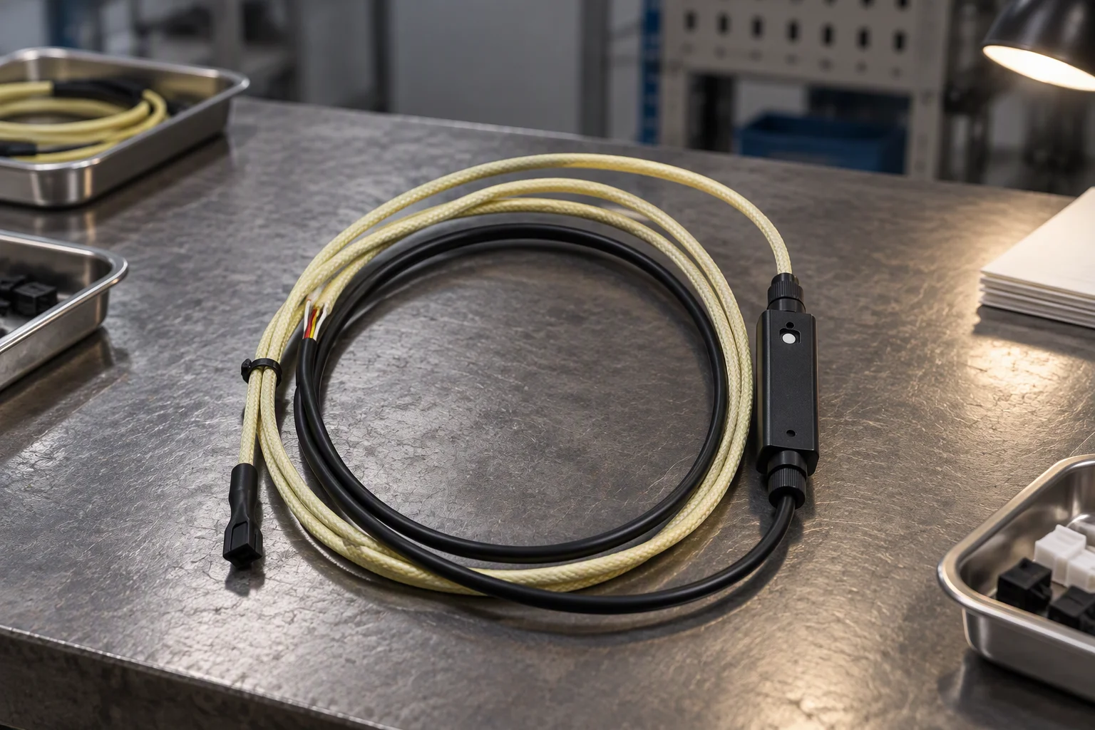
A sensing cable assembly on a bench: a braided section and a black jacketed section joined by an in-line module with a gland at each end, plugs at both ends of the assembly
FIG 4 ·

The module sits in the run rather than at the controller, so a break in the cable stays addressable.
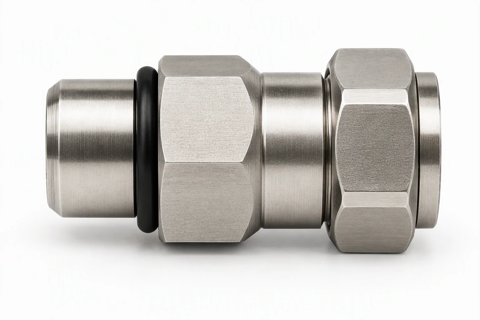
A metal fitting on a neutral ground with its thread and sealing face visible, photographed on its own
FIG 5 ·

The interface is fixed by a drawing, not by what the fitter has on the van.

05

The loop as a sealed cabinet is actually built

Section through the cabinet · consumables called out where they sit

1 2 3 4 5 6 sealed cabinet · the loop and the alarm live in the same box

Consumables on this section

  1. 1 ·Finned heat exchanger on the cabinet wall, ambient side
  2. 2 ·Pump and reservoir on the floor pan, serviceable through the door
  3. 3 ·Controller with the dry contact pair and its antenna
  4. 4 ·Locating sensing cable in the base pan, under the joints
  5. 5 ·Drip tray under the coupling pair, dry in normal service
  6. 6 ·Hose run clipped to the wall, never hanging on a joint
06

The three files this industry is held as

Archive form · no client name and no project name is held on any of them

Three configurations recur at unattended sites. Each is held as a file: the loop drawing, the consumable list, the cleanliness gate and the sample that cleared it.
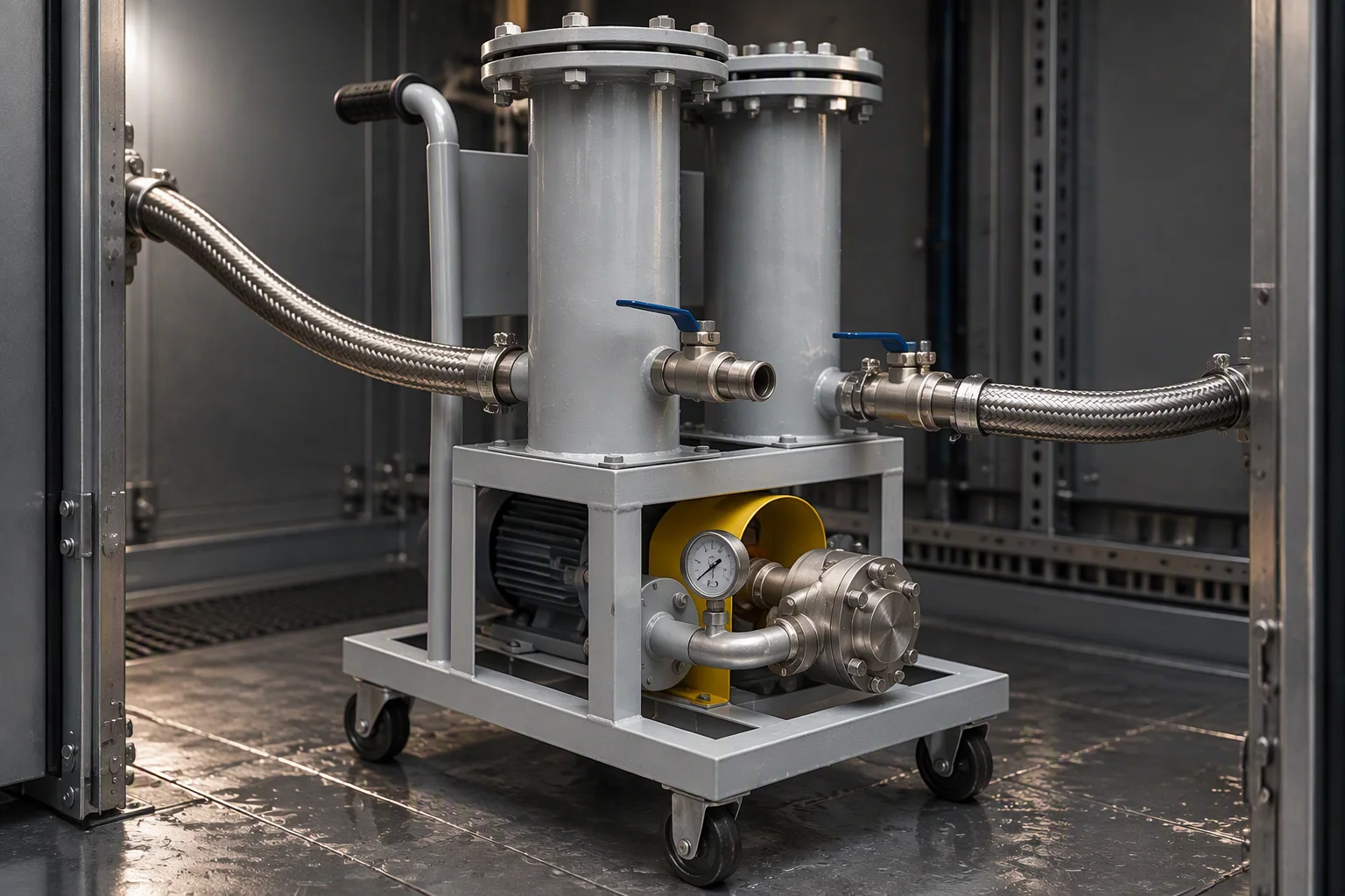
A short cabinet loop: two cartridge housings side by side on a trolley with a valve and a gauge between them and a hose at each end, compact enough to pass a service opening
FIG 6 ·

File A. One short loop, filter and valve in the cabinet.
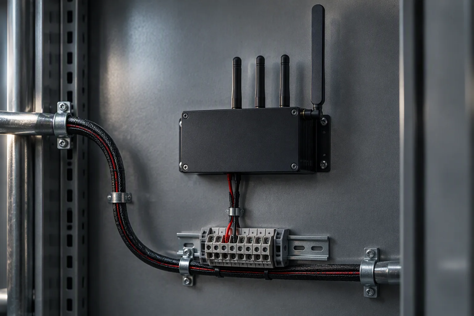
A controller on the inside wall of a cabinet above a terminal block, alarm cores landed on the terminals and the antenna against the wall
FIG 7 ·

File B. The alarm lands on terminals in the same box as the loop.
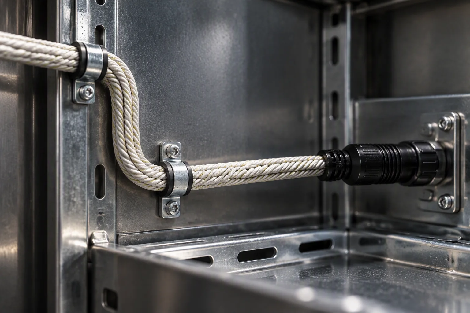
A braided cable run inside a cabinet turning through two bends, clipped into a channel with plugs fixed to the tray, nothing hanging free
FIG 8 ·

File C. The cable route: clipped, grommeted and gated, so a door never closes on it.

07

The standards a remote cabinet is written against

Conformity · the document set held for this sheet

OCP
Cold Plate Coolant Base Specification v1.3, with the Reservoir and Pumping Unit Spec v1.0 for the facility side
ASHRAE
Water Cooled Servers, supply-water classes W17–W45.
T/CAEE 085—2026
EPDM hose and hose assemblies for cold-plate liquid cooling, water-based coolant
ISO 4406
17/15/12 before the cabinet loop is closed, verified on a sample
ISO 9001
Held by the partner carrying the work, not claimed here as ours
EN 10204 3.1
Material certificates for every metal part in the loop
UL 94 V-0
Flame rating on the hose cover compound
RoHS · REACH
Elastomer and seal material compliance
CE · UKCA
CE marking and UKCA, for European delivery
04

How those standards are demonstrated

Evidence plates · the batch bench, the seal set, and how a cabinet kit ships

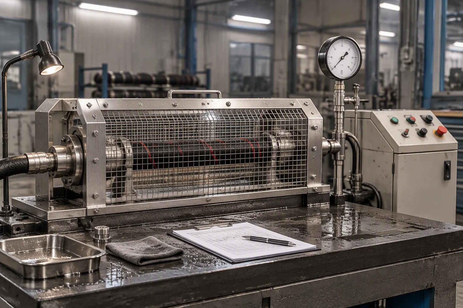
A hydrostatic and burst test bench with a coiled braided hose under test behind a steel guard, a pressure gauge and control cabinet at the side
FIG 9 ·

1.38 MPa working and burst above 5.5 MPa, with the record travelling to the site.
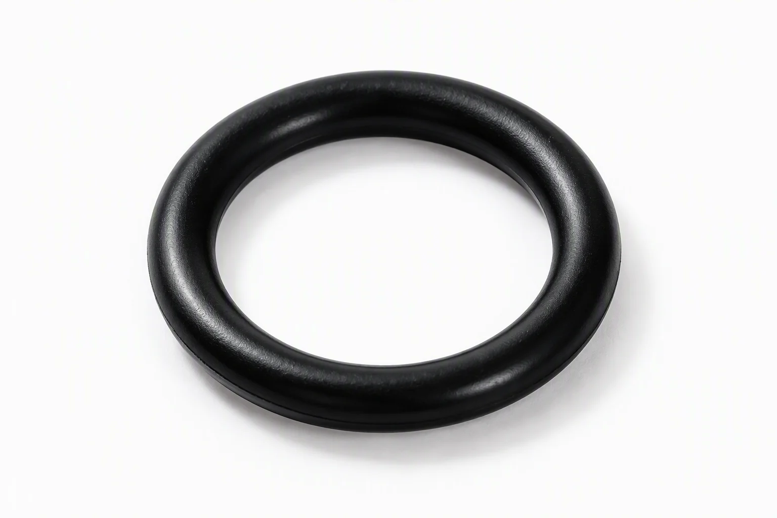
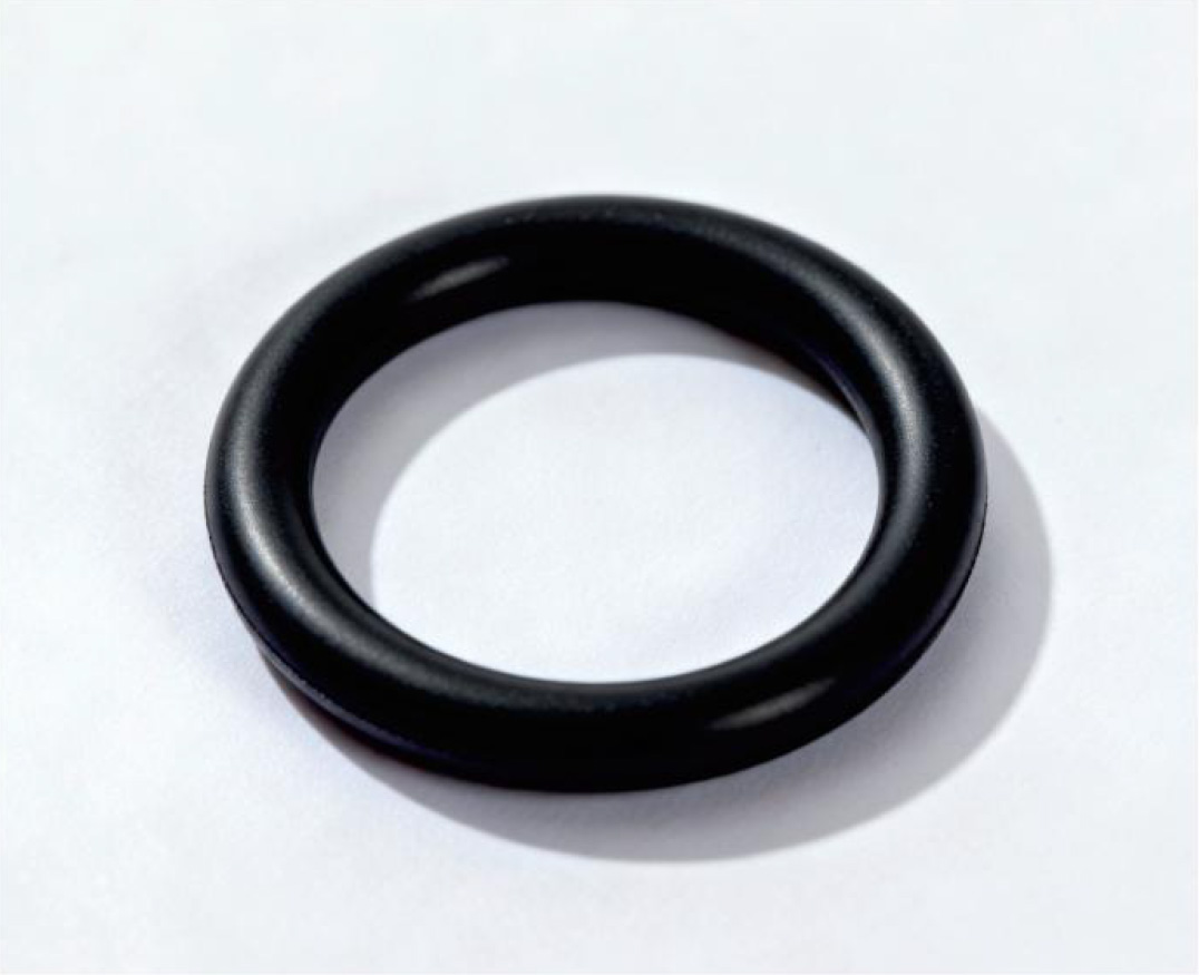
A single black O-ring on a light ground photographed close, with its contact shadow beneath it
FIG 10 ·

The seal is the part that has to hold through the whole −20 to +55 °C band.

A cabinet kit leaves with the loop closed, terminated and pressure tested, so that the only work on site is landing it on the tray and closing the door on a loop that already holds.
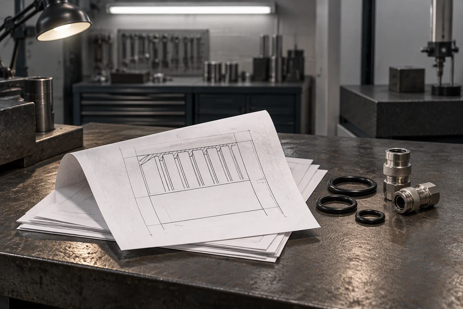
The document set for a cabinet loop laid out on a bench: a folded drawing over a small stack of sheets, seal rings and a coupling pair beside them
FIG 11 ·

The drawing, the certificates and the test record are packed with the kit, not sent after it.

05

What every one of those files consumes
Specimen strip · real parts, one cell each · contain fit, the part is never cropped

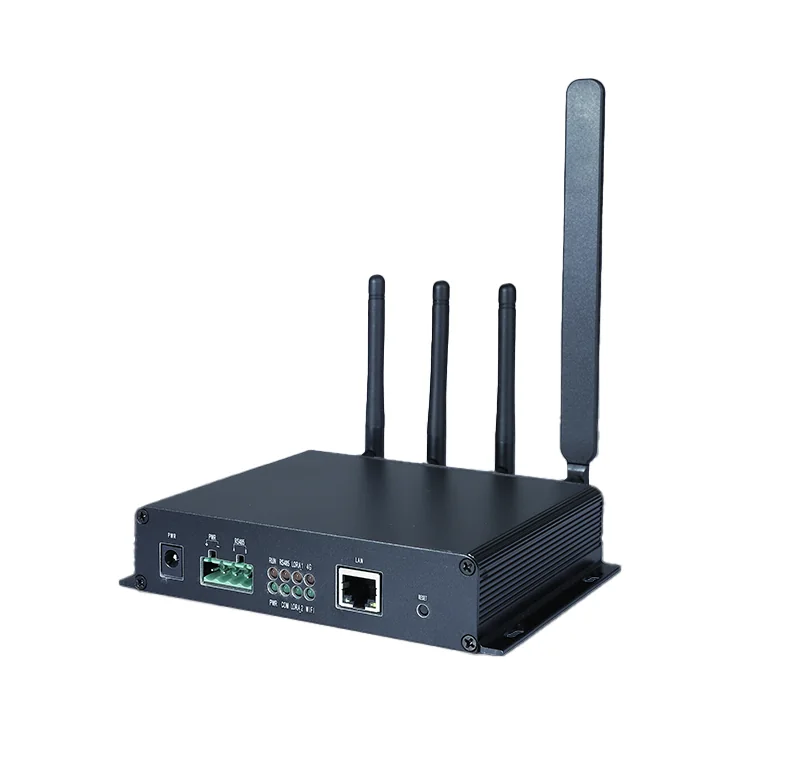
A black controller unit on a white ground with four antennas and a terminal block along its lower edge, a network port and a power inlet on the front face
SP 1 · Local alarm unit Reports out, and alarms where it stands
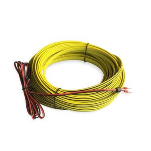
A coil of yellow flat sensing cable with a twisted red and black pair and a small black terminator, held with two ties on a white ground
SP 2 · Sensing cable 0.1 m resolution, 500 m per channel
A single black O-ring on a light ground, photographed with its contact shadow
SP 3 · Seal set Replaced at every break in the run
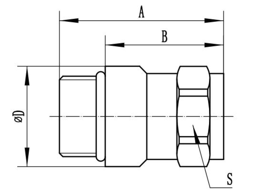
Dimension drawing of a threaded fitting with A, B, D and S callouts, no brand and no model number
SP 4 · Fitting drawing Outline drawing ships with the batch

SP 1–4 ·Supply-side samples: a controller unit that reports out and alarms where it stands, a flat sensing cable rated 0.1 m resolution on 500 m per channel, the seal that has to hold across the whole ambient band, and the outline drawing that fixes the interface.

00

What stops at the boundary of this sheet

Scope · the part of the loop that is not supplied here

We supply the loop: hose, couplings, seals, filtration, sensing rope and the instruments that read them. The cooling distribution unit and the cold plate are not ours to quote, and neither is the installation, the design or the commissioning of either.

At a kerbside cabinet that boundary is the practical one: power, backhaul and mounting are somebody else's scope, and the loop plus its alarm are ours.
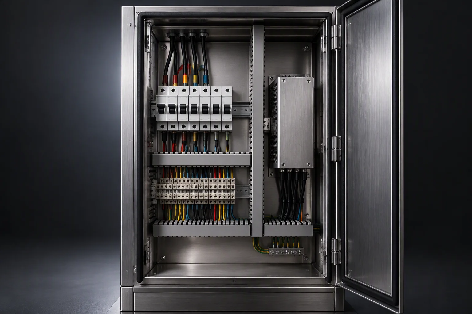
Supplied the loop itselfNot supplied CDU · cold plate · installation
The power and backhaul compartment of an outdoor cabinet: a row of breakers and terminal blocks, a power module and a wiring duct, with a partition separating it from the liquid compartment
FIG 12 ·

The supply, the backhaul and the site stay with the site. What we quote is the loop and the alarm that leaves it.

00

The other sheets in this set

The same schedule, five different industries · one row per sheet

01 Colocation A hall that cannot be shut down, on a return shared with other tenants. SLA 99.99% · 52.6 min
02 Hyperscale & AI training Rack power from 10–15 kW to 100 kW+, and a coupling pair added with every rack. 10–15 → 100 kW+
03 HPC & research One loop, two equipment generations, 5–10 years, and no baseline sample. 5–10 years
04 Semiconductor Particles read against yield, on wetted parts declared as 316L and PFA. 0.05–100 µm
05 EV & power electronics Bench loops broken and remade weekly, and glycol errors that surface weeks later. 1.38 MPa · −40 to +99 °C

Every sheet in this set is written in the same order: the pain, the schedule it is quoted on, the loop as it is built, the standards, and the configuration files held for it.

DOCUMENT REQUEST

Four documents are held for this sheet. Tick the ones you need.

Tick a document, name the cabinet or the site run you are planning against, and the file comes back attached.

The only promise on this page

One business day, with the file attached.

Nothing else on this sheet is a commitment. Price, stock and lead time are not promised here.

The four documents held for this sheet laid out on a bench: a folded specification sheet, a certificate sheet, a test report and a rolled outline drawing
FIG 13 · Specification sheet · EN 10204 3.1 certificates · burst and hydrostatic report · outline drawings
If the form cannot send, sales@ems-cool.com takes the request instead. A request is never accepted and then dropped.