EMS-Trade
Cooling
Loop consumables

Document ECT-01 · REV C · ISSUED 2026-09 Six lines · 48 sheets

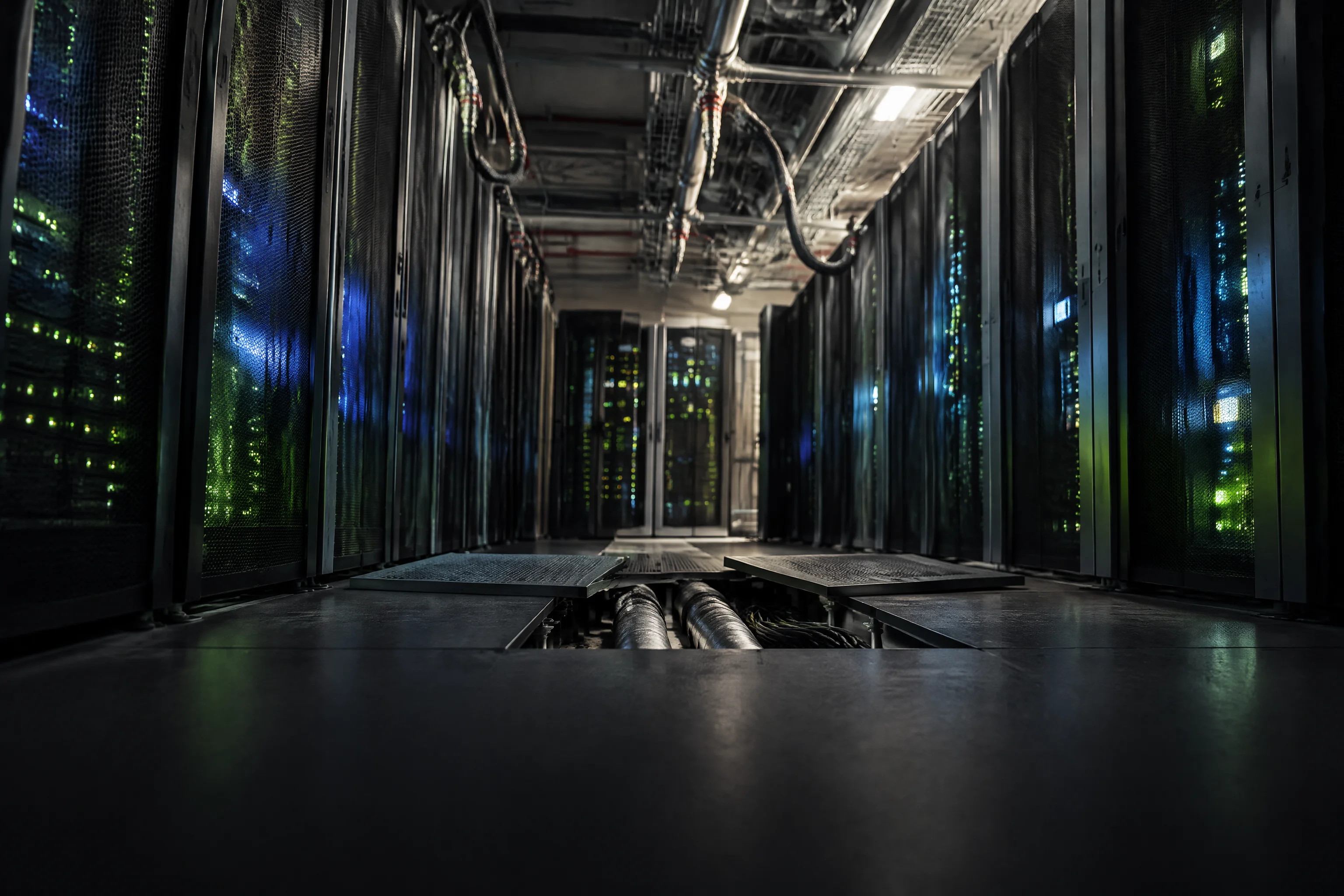
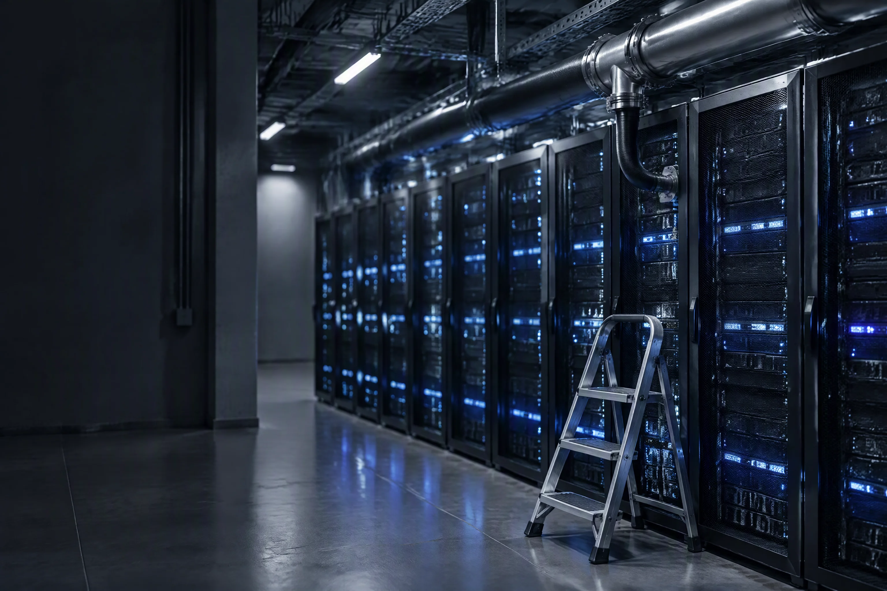
A colocation hall in service seen from floor level: two rows of lit cabinets, ceiling coolant mains with a coupling pair and a hose drop at each cabinet, and two floor tiles lifted beside the aisle
Sheet 38 · Colocation · the live hall

The hall stays live while the loop changes

Work goes on inside a hall that cannot be shut down, on a loop shared with other tenants. Everything here is written for the change that has to be made without a shutdown window.

99.99%Tenant SLA in the contract
52.6 minDowntime a year that allows
0.1 mLeak location, 500 m per channel
Request the specification file One business day, with the file attached
01

Live bus · shared loop · contract clock · where it lands

Pain statement · the conditions this industry actually runs under

Live bus
The hall is in service. No hot work, no core drilling above the tiles, and no shutdown window to ask for. Every part arrives finished and goes in from the aisle.
Shared loop
One return serves several tenants. A coupling that weeps at one rack reaches another tenant's intake as a humidity trend, not as a work order.
Contract clock
Tenant agreements are commonly written to 99.99%, which is 52.6 minutes of downtime in a year. One underfloor leak spends it before anyone agrees what happened.
Where it lands
Fluid arrives under the floor while the inspection round walks on top of it. Detection has to live where the fluid goes, not where the round goes.
02

What working live looks like in the aisle
Pain plates · the hall in service, the shared return, the wet slab

An aisle of running cabinets with a folding work platform against one row, a new branch and two clamps added to the coolant main above, the floor tiles still closed

In service the row keeps running while the branch is tied in

No hot work and no core drilling above the tiles

1 row is the unit a tenant branch can be isolated at

FIG 1 ·

Every decision on this sheet starts from the same fact: the room is occupied while the work happens.
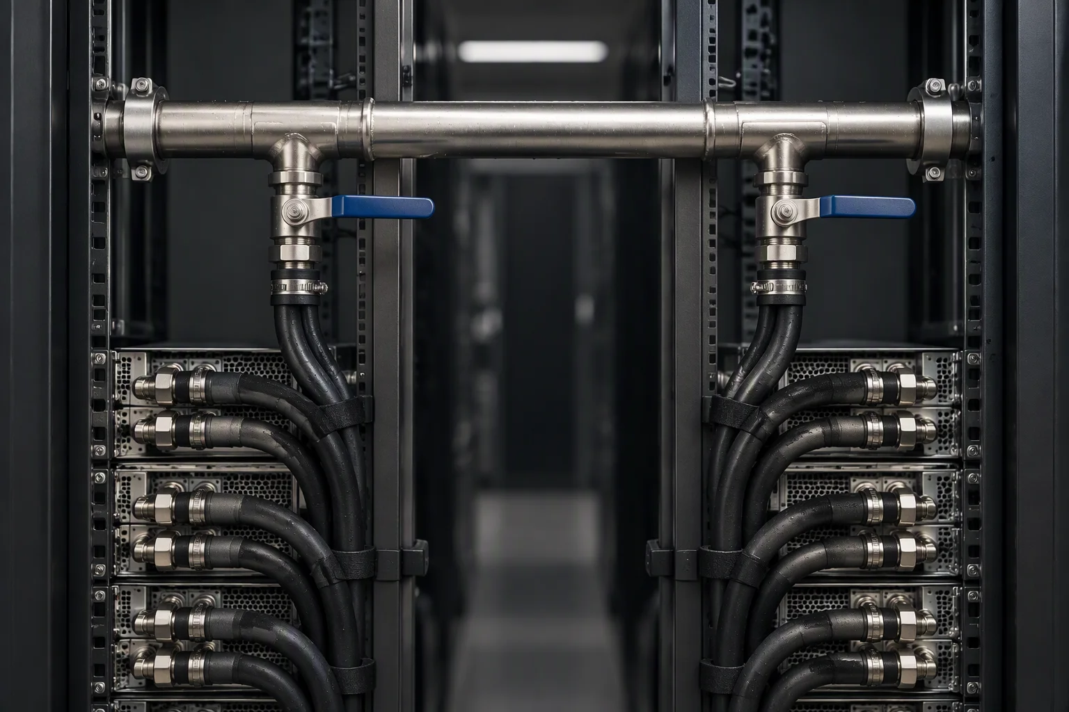
The rear of a cabinet row: a common return main with two separate branches rising from it to two groups of adjacent cabinets, each branch with its own isolation valve
FIG 2 ·

Two tenants, one return. A drip on one branch is read as a humidity trend on the other.
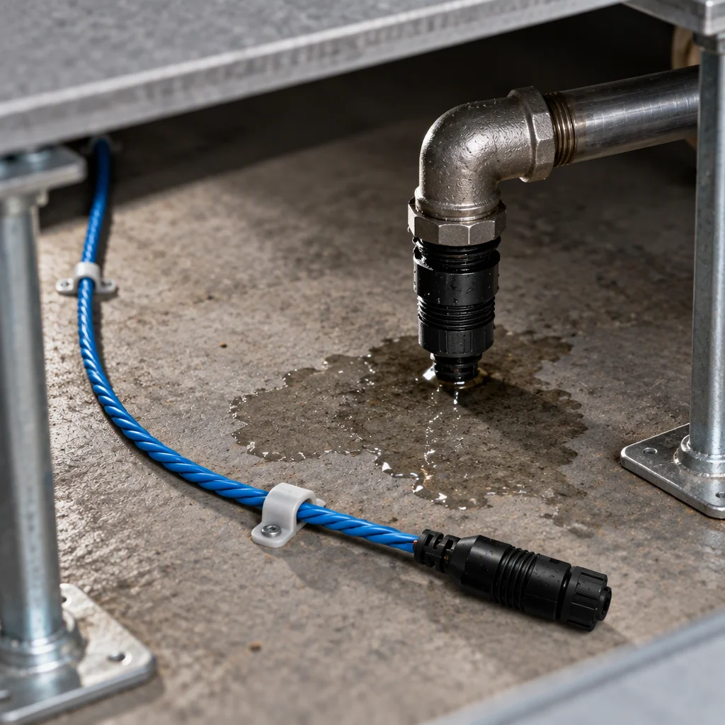
The void under a raised floor seen from above: a small spread of fluid on the slab from below a pipe joint, with the sensing cable run along the slab beside it
FIG 3 ·

The wet slab is the first evidence, and it is under a floor nobody has lifted yet.

02

What we will put in writing for a live hall

Schedule C · acceptance conditions for the loop, not for the CDU

Schedule C · the conditions this industry is quoted on
No Condition Value Unit Basis
01 Leak location resolutionLocating sensing rope 0.1 m Under the tiles, along the pipe the fluid would follow
02 Detection length per channelLocating sensing rope 500 m A whole aisle on one channel, position not zone
03 Alarm responseController to the BMS 30 s Inside the window a tenant contract is written to
04 Contract downtime a yearTenant SLA 99.99% 52.6 min One underfloor leak can spend it in an afternoon
05 Isolation per tenantBranch valve at the take-off 1 row One tenant's branch can be shut without the row
06 Cartridge absolute ratingFilter on the branch 1 µm Grades from 0.05 to 100 µm on one housing
07 Cleanliness at chargeLoop fluid 17/15/12 ISO 4406 Sampled before any retrofit run is charged
08 Filter change differentialAcross the housing 0.5–0.7 bar Read on two impulse tubes, not on a gauge by eye
09 Hose working pressureDASH −4 to −10 1.38 MPa About 200 psi, burst above 5.5 MPa
10 Hose temperature bandWater-based coolant −40 to +99 °C The band claimed for this application

The value column is the figure we will be held to, and every figure in it is one this loop is bought against. Where a tolerance is not published, the cell stays empty rather than carrying an estimate.

03

Where the two readings on a tenant branch come from
Evidence plates · the filter differential, and the rope under the slab

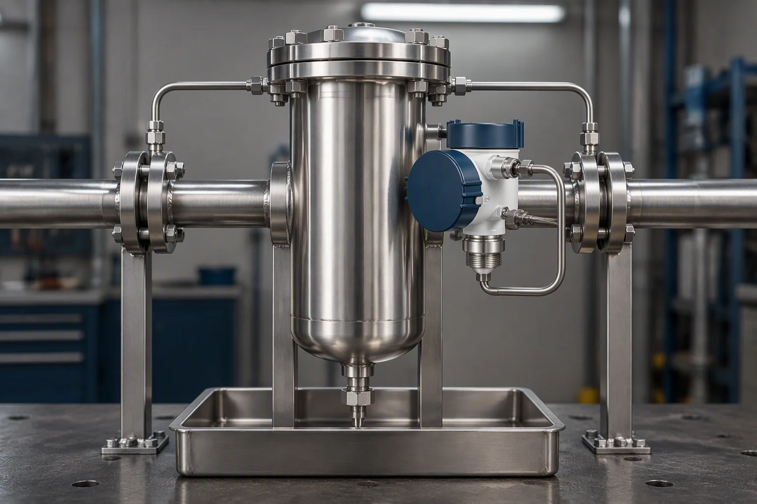
A cartridge filter on a cabinet branch with a differential pressure transmitter on its side, two impulse tubes taken across the housing and a drip tray underneath
FIG 4 ·

Filter loading is the first reading that moves when a branch stops delivering.
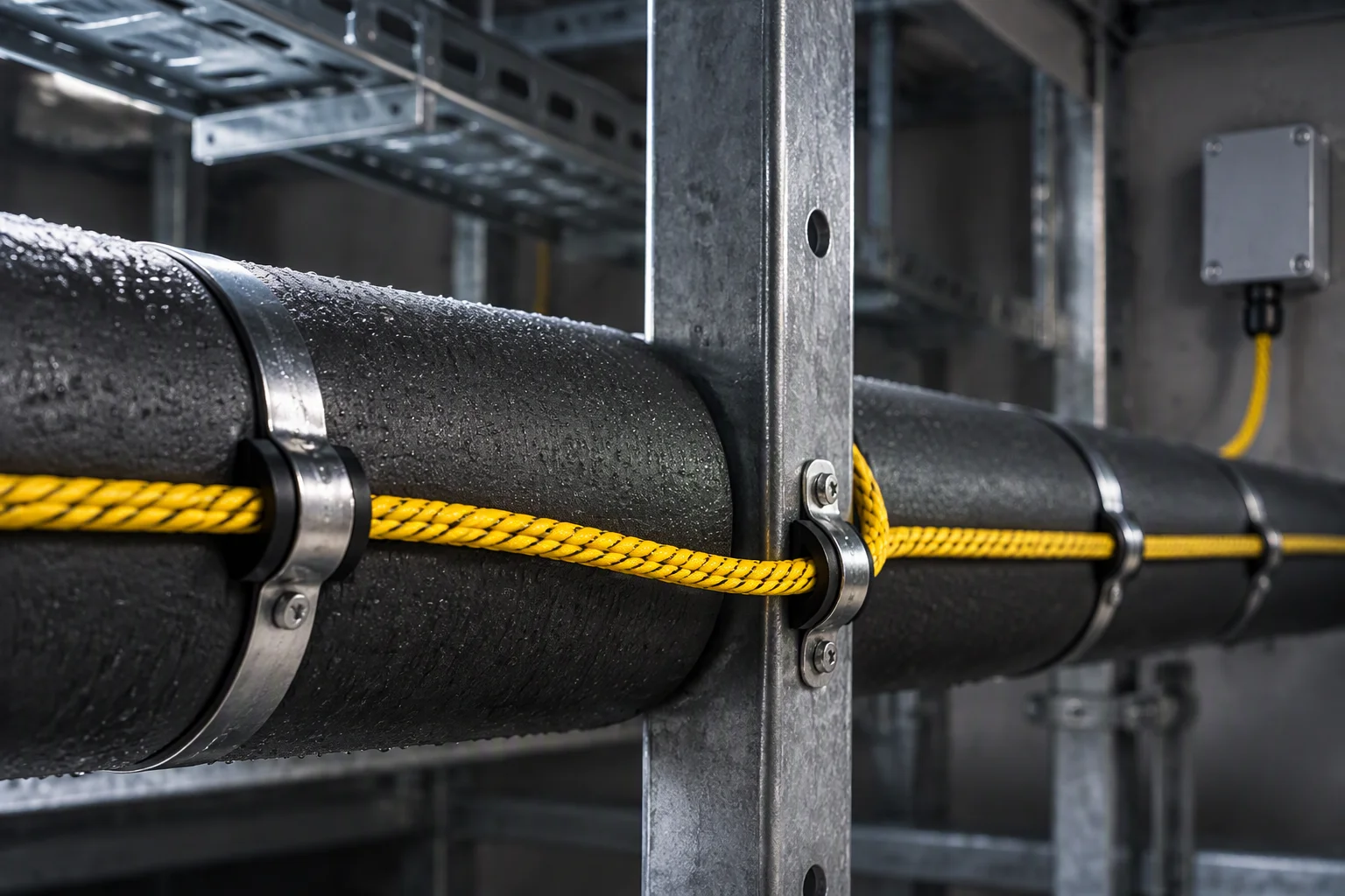
A lagged chilled water pipe under a raised floor with a braided sensing cable run along it, turning past a pedestal towards a wall terminal box
FIG 5 ·

The rope follows the run the fluid would follow, past every joint on it.

05

The loop as a colocation retrofit is actually built

Section through the slab and one tenant branch · consumables called out

1 2 3 4 5 6 slab void · fluid arrives here before the round sees it

Consumables on this section

  1. 1 ·Suspended floor tiles · the work happens below them, in service
  2. 2 ·Existing chilled water pipe, lagged and left in place
  3. 3 ·Locating sensing rope run along the slab beside the pipe
  4. 4 ·Point sensor under a coil and a valve group
  5. 5 ·New tenant branch, isolation valve at the take-off
  6. 6 ·Filter and differential pressure transmitter on the branch
06

The three files this industry is held as

Archive form · no client name and no project name is held on any of them

Three configurations recur in tenant halls. Each is held as a file: the loop drawing, the consumable list, the cleanliness gate and the sample that cleared it.
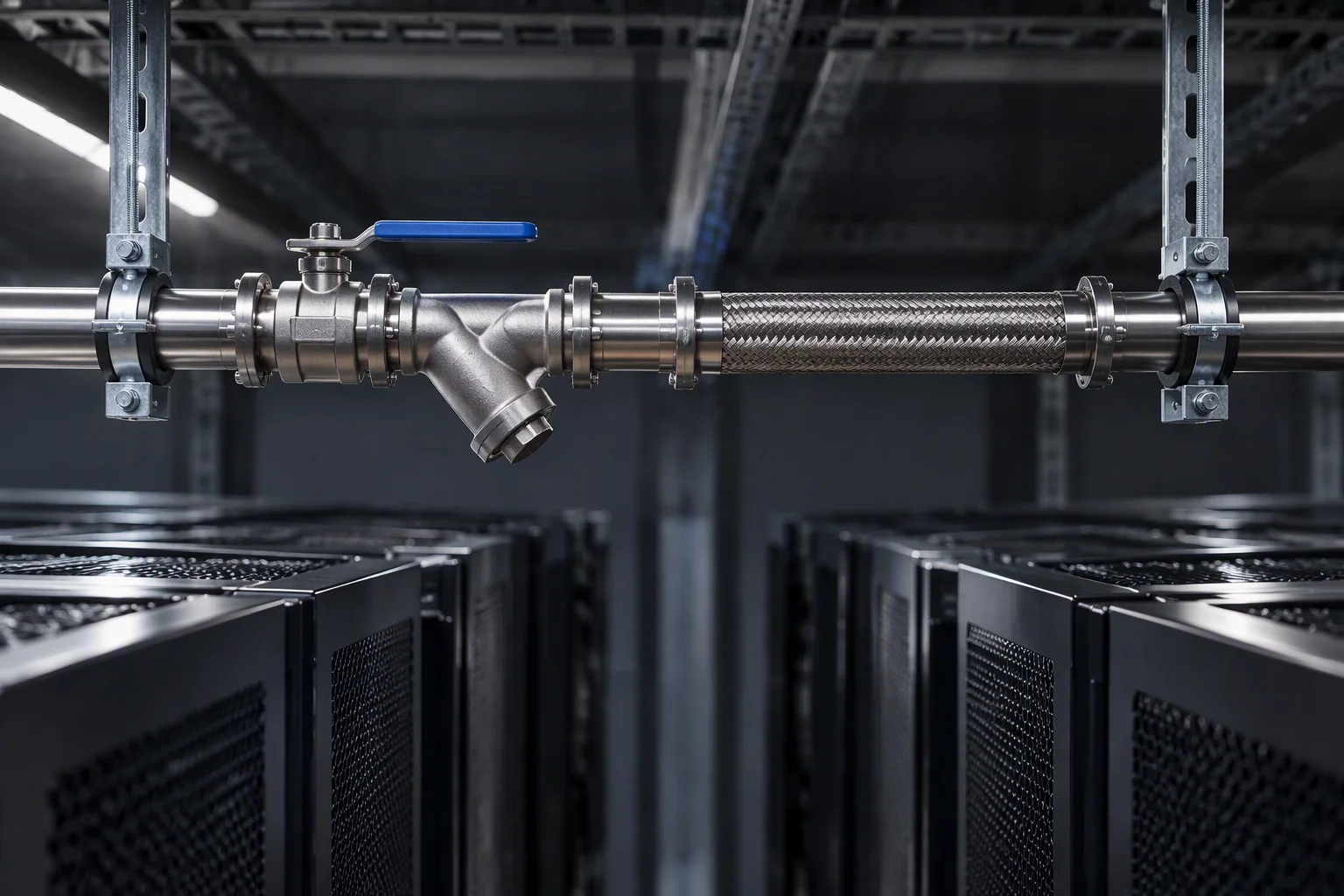
One branch taken off a main to serve a single group of cabinets, with its own isolation valve and filter, crossing no other branch
FIG 6 ·

File A. One tenant, one branch, isolation at the take-off.
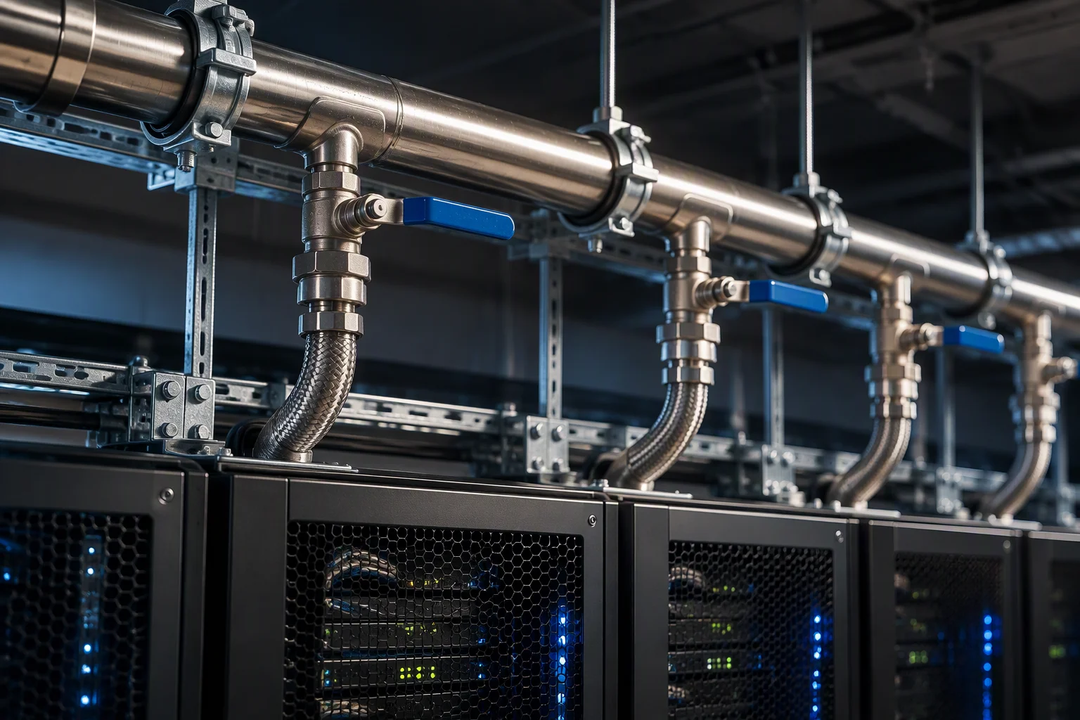
A row manifold above a cabinet row with several branches leaving it, each branch with a lever isolation valve facing the service aisle
FIG 7 ·

File B. One manifold per row, every branch isolatable from the aisle.
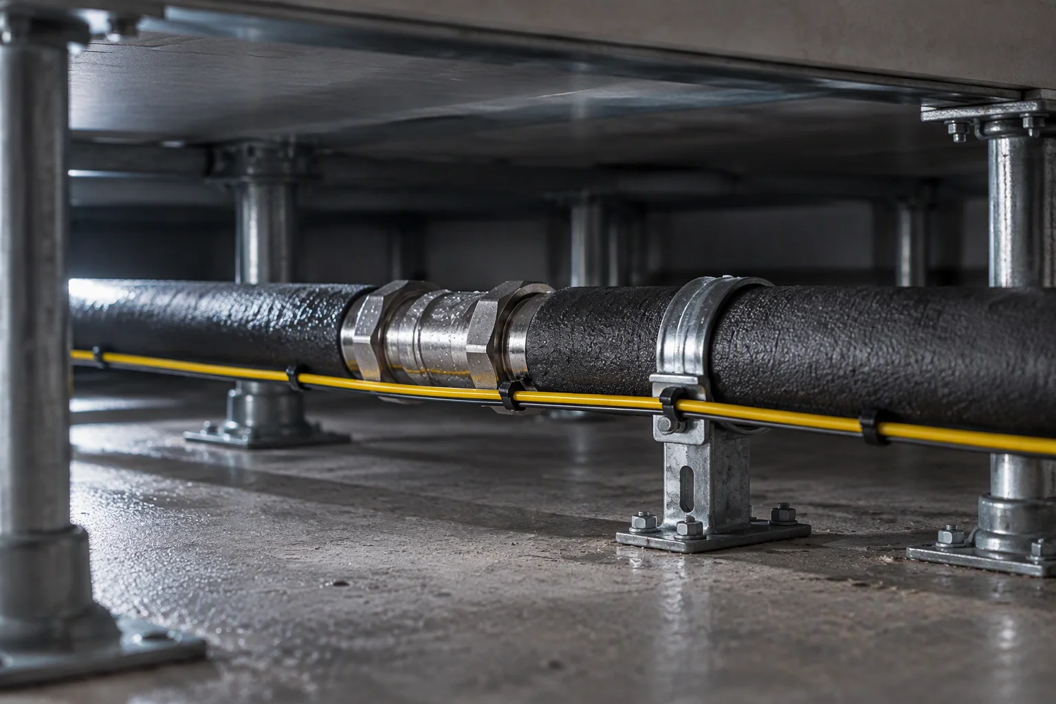
Under a raised floor: the existing lagged pipe left in place with a new branch laid alongside it between the pedestals, a joint and a support on the new run
FIG 8 ·

File C. The retrofit run: existing pipe untouched, new run beside it.

07

The standards a tenant hall is written against

Conformity · the document set held for this sheet

OCP
Cold Plate Coolant Base Specification v1.3, with the Reservoir and Pumping Unit Spec v1.0 for the facility side
ASHRAE
Water Cooled Servers, supply-water classes W17–W45.
T/CAEE 085—2026
EPDM hose and hose assemblies for cold-plate liquid cooling, water-based coolant
ISO 4406
17/15/12 before the retrofit run is charged, verified on a sample
ISO 9001
Held by the partner carrying the work, not claimed here as ours
EN 10204 3.1
Material certificates for every metal part in the loop
UL 94 V-0
Flame rating on the hose cover compound
RoHS · REACH
Elastomer and seal material compliance
CE · UKCA
CE marking and UKCA, for European delivery
04

How the same standards are demonstrated to a tenant
Evidence plates · the batch bench, the seal set, and how a retrofit ships

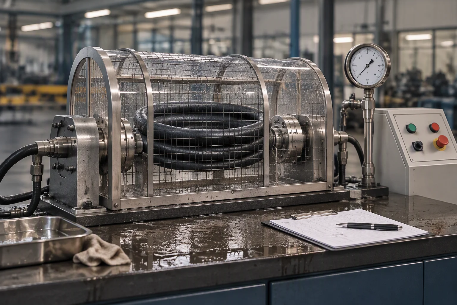
A hydrostatic and burst test bench with a coiled braided hose under test behind a steel guard, pressure gauge and control cabinet at the side
FIG 9 ·

1.38 MPa working, burst above 5.5 MPa, and the record travels with the shipment.
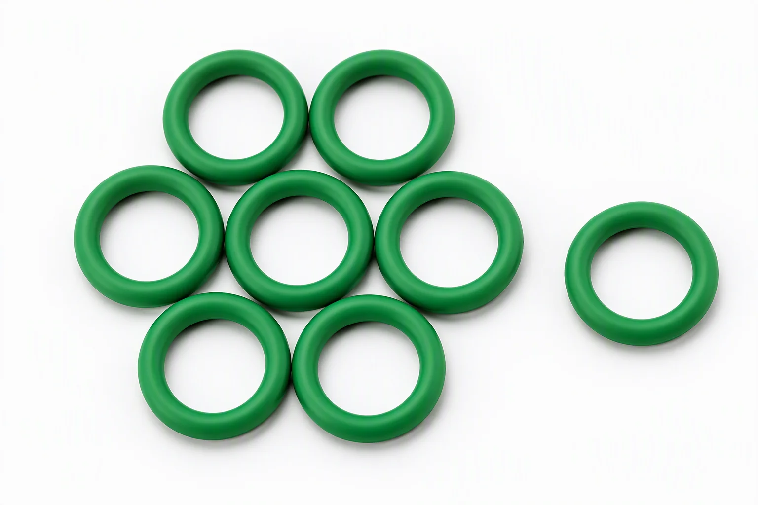
A row of green O-rings laid out on a neutral ground, one ring separated from the group
FIG 10 ·

The seal set is a line item, not an accessory: it is replaced at every break.

A retrofit shipment is packed so that nothing has to be fabricated on the slab: hose cut to length, ends terminated, seals bagged against the joint they belong to. What arrives in the aisle is what goes into the loop.
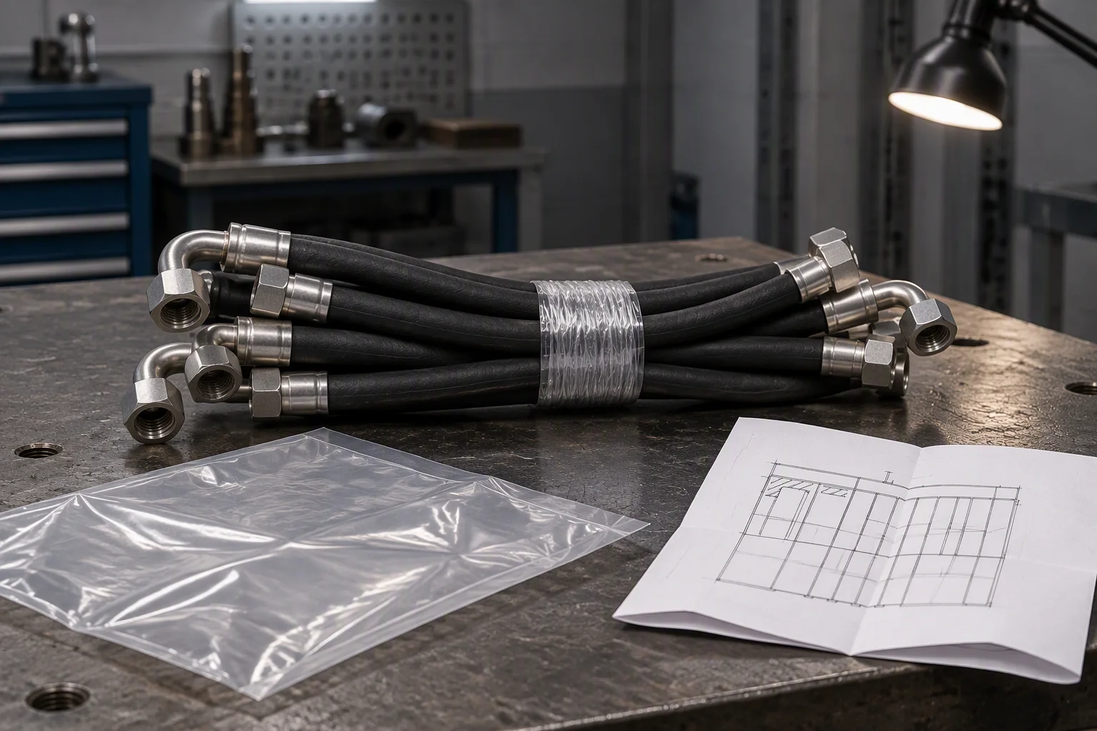
A batch of retrofit parts on a bench: terminated hose lengths bundled with wrapping tape, a bag and a folded drawing beside them
FIG 11 ·

Cut and terminated before dispatch, so the aisle is never the place the length is decided.

05

What every one of those files consumes
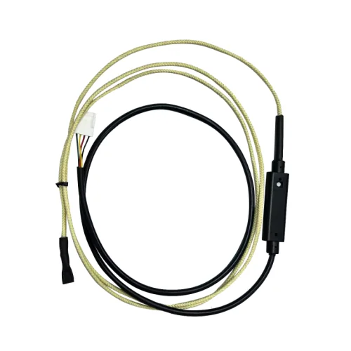
Specimen strip · real parts, one cell each · contain fit, the part is never cropped

A sensing cable assembly coiled on a white ground: a braided run alongside a black cable with an in-line connector module, and a white plug on the lead
SP 1 · In-line sensing run Module in the run, not at the controller
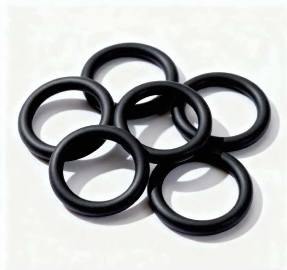
A group of black O-rings resting on a light ground, one ring slightly apart from the others
SP 2 · Seal set Changed at every break in the run
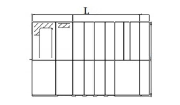
Section drawing of a body with a machined bore and a hatched wall, dimension lines only, no brand and no model number
SP 3 · Body section Bore and wall drawn, not estimated
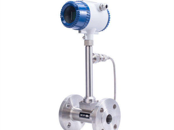
Electromagnetic flow meter with a transmitter head on a flanged stainless body, photographed on a white ground
SP 4 · Tenant branch flow One reading per tenant branch

SP 1–4 ·Supply-side samples: an in-line sensing run with its module in the middle of the cable rather than at the controller, a seal set replaced at every break, a body section drawing with the bore and wall called out, and the flow meter that reads one tenant branch.

00

What stops at the boundary of this sheet

Scope · the part of the loop that is not supplied here

We supply the loop: hose, couplings, seals, filtration, sensing rope and the instruments that read them. The cooling distribution unit and the cold plate are not ours to quote, and neither is the installation, the design or the commissioning of either.

In a tenant hall that boundary matters twice over: the unit you already own stays yours, and this sheet covers only what hangs off it.
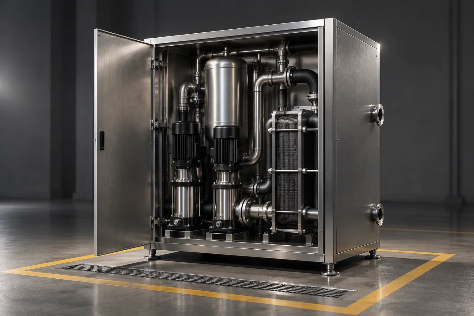
Supplied the loop itselfNot supplied CDU · cold plate · installation
A coolant distribution unit in a plant room corner with its doors half open on pumps, a tank and a heat exchanger, a marked maintenance aisle in front of it and a free equipment bay beside it
FIG 12 ·

The unit on the facility side stays the facility's. This sheet starts at the flange on it.

00

The other sheets in this set

The same schedule, five different industries · one row per sheet

01 Hyperscale & AI training Rack power from 10–15 kW to 100 kW+, and a coupling pair added with every rack. 10–15 → 100 kW+
02 HPC & research One loop, two equipment generations, 5–10 years, and no baseline sample. 5–10 years
03 Edge & telecom No round, no one on call, and a leak that can run for weeks. −20 to +55 °C
04 Semiconductor Particles read against yield, on wetted parts declared as 316L and PFA. 0.05–100 µm
05 EV & power electronics Bench loops broken and remade weekly, and glycol errors that surface weeks later. 1.38 MPa · −40 to +99 °C

Every sheet in this set is written in the same order: the pain, the schedule it is quoted on, the loop as it is built, the standards, and the configuration files held for it.

DOCUMENT REQUEST

Four documents are held for this sheet. Tick the ones you need.

Tick a document, name the row or the tenant branch you are planning against, and the file comes back attached.

The only promise on this page

One business day, with the file attached.

Nothing else on this sheet is a commitment. Price, stock and lead time are not promised here.
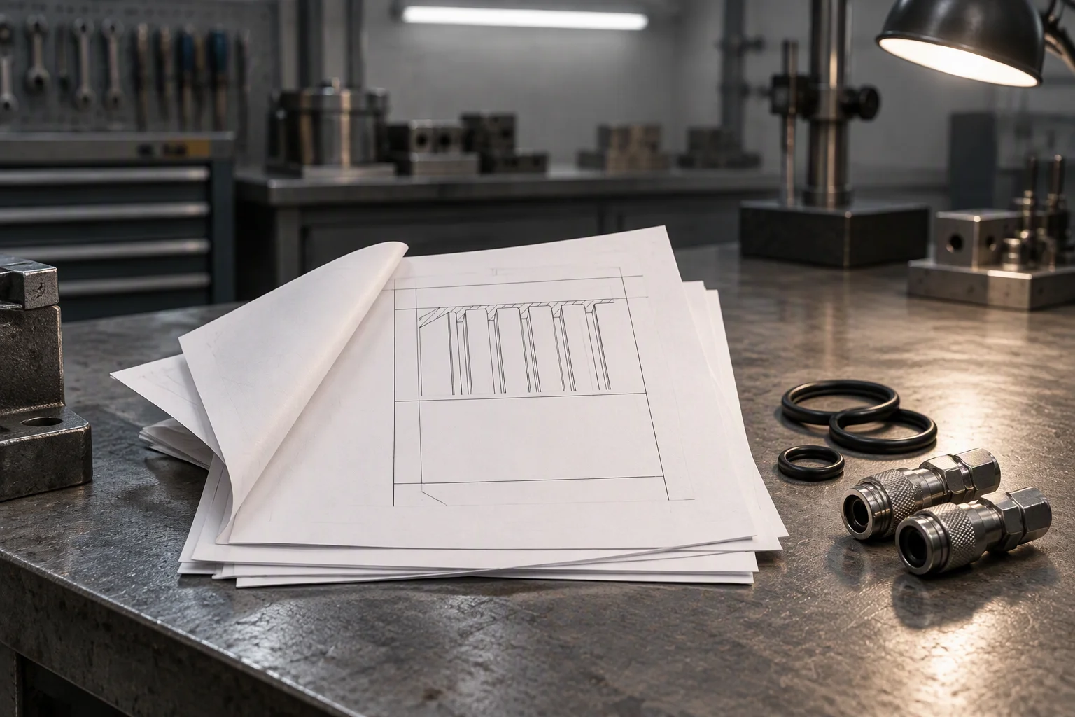
The four documents held for this sheet laid out on a bench: a folded specification sheet, a certificate sheet, a test report and a rolled outline drawing
FIG 13 · Specification sheet · EN 10204 3.1 certificates · burst and hydrostatic report · outline drawings
If the form cannot send, sales@ems-cool.com takes the request instead. A request is never accepted and then dropped.