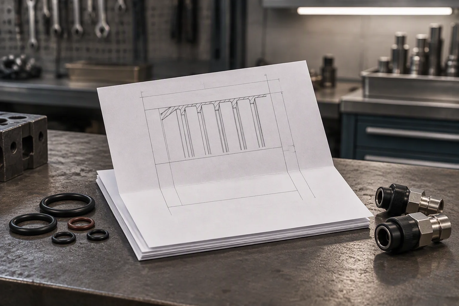
The loop outlives the equipment it was built for
One loop carries equipment from two generations for 5–10 years, and the sample that would define its normal state was never kept.
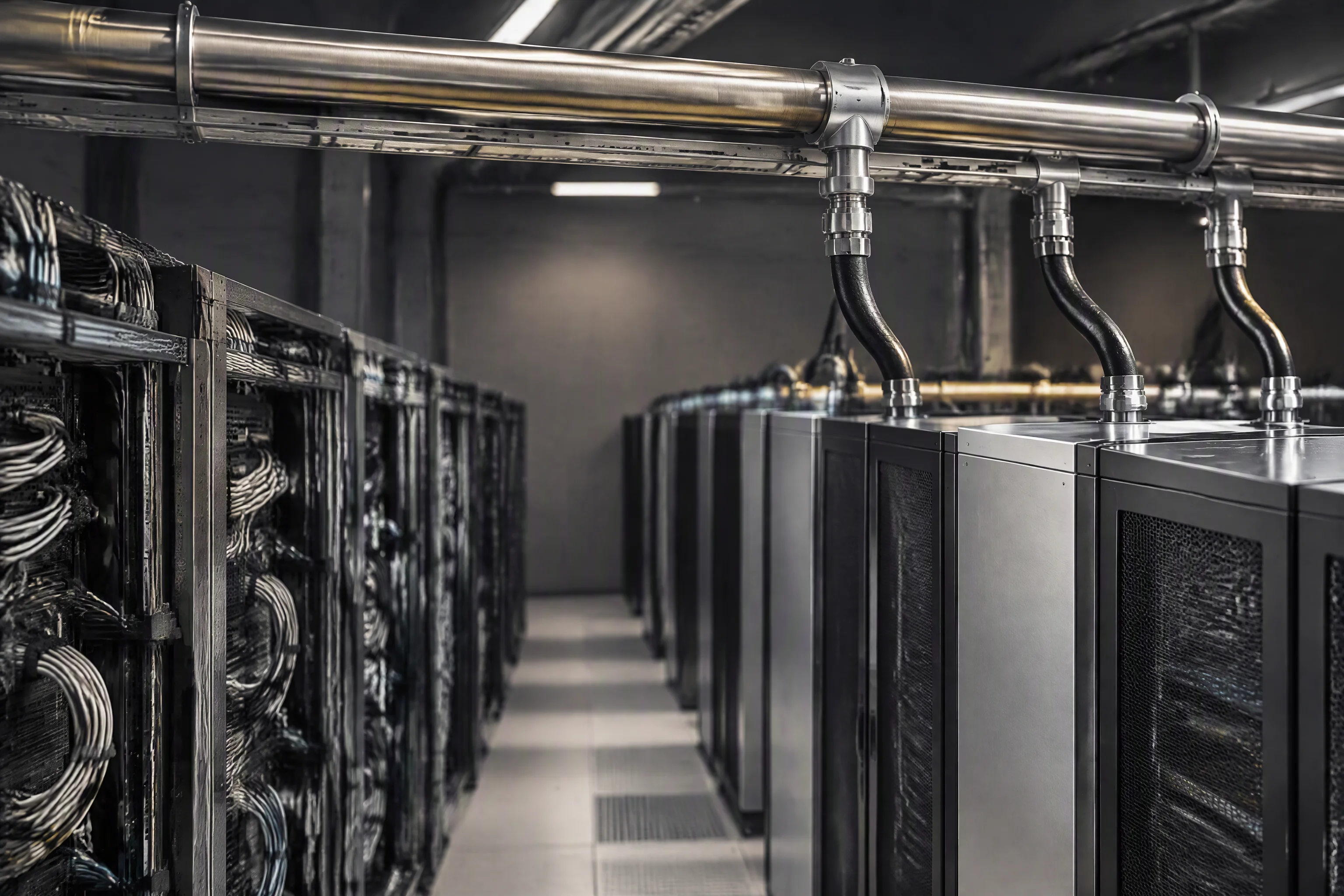
One manifold, two generations, one fluid. The loop is older than every machine on it.
Four facts that decide how this loop is specified
A baseline is not a document the supplier keeps for you. It is a sample drawn on the day the loop is filled, and it belongs in the same file as the loop drawing.
What a ten-year loop looks like from the aisle
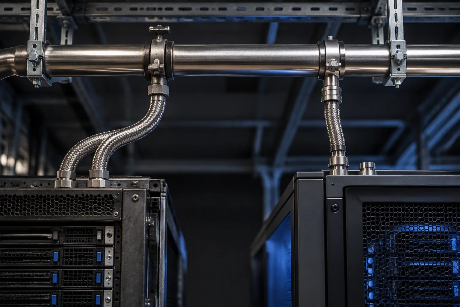
The tee between the two generations is a joint, and it was made ten years after the first one.
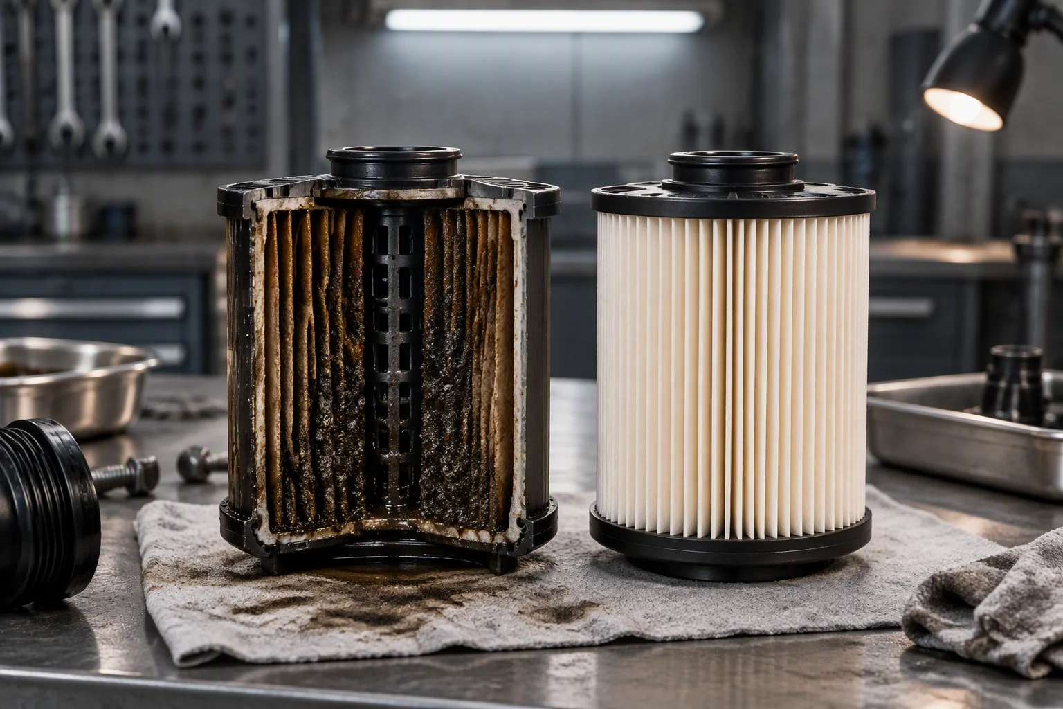
What the element holds is what has been circulating: the filter is the loop's only account of it.
The probe is where the baseline argument lands. It is pulled, wiped and put back at every service, and its reading stays an opinion until there is a first sample to hold it against. Holding that sample costs one bottle and one line in the file.
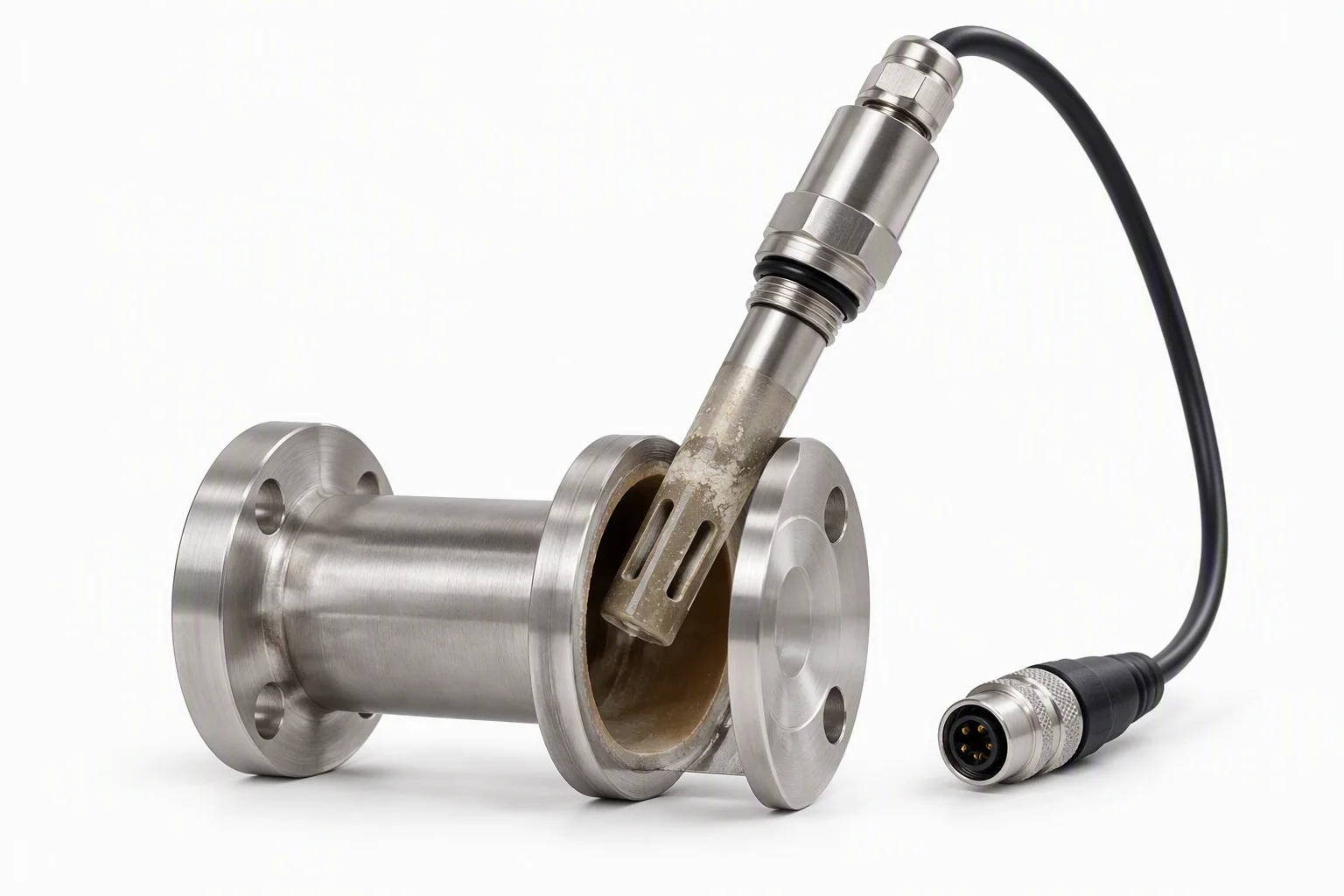
Conductivity is the reading that reports inhibitor depletion, and it is only meaningful against a baseline.
What we will put in writing for a ten-year loop
| No | Condition | Value | Unit | Basis |
|---|---|---|---|---|
| 01 | Service band of one loopHose, seals and filtration | 5–10 | years | Specified once, then carried through several equipment generations |
| 02 | Inhibitor service lifeIn reported loops | Third | year | Depletion is reported from the third year onward, as a conductivity shift |
| 03 | Baseline sampleOn the day the loop is filled | 1 | sample | Conductivity, pH and cleanliness, kept with the loop drawing |
| 04 | Cleanliness at charge and top-upLoop fluid | 17/15/12 | ISO 4406 | Top-up fluid is gated to the same grade as the first fill |
| 05 | Cartridge absolute ratingFilter grade in circuit | 1 | µm | Grades from 0.05 to 100 µm on one housing |
| 06 | Filter change differentialAcross the housing | 0.5–0.7 | bar | Read continuously, not at the annual service |
| 07 | Leak location resolutionLocating sensing rope | 0.1 | m | On 500 m of rope per channel, alarm inside 30 s |
| 08 | Shell design pressure304 and 316L | 1.0 | MPa | Hydrostatic proof per batch |
| 09 | Hose working pressureDASH −4 to −10 | 1.38 | MPa | About 200 psi, burst above 5.5 MPa |
| 10 | Hose temperature bandWater-based coolant | −40 to +99 | °C | The band claimed for this application |
The value column is the figure we will be held to, and every figure in it is one this loop is bought against. Where a tolerance is not published, the cell stays empty rather than carrying an estimate.
Where the two readings on a ten-year loop come from
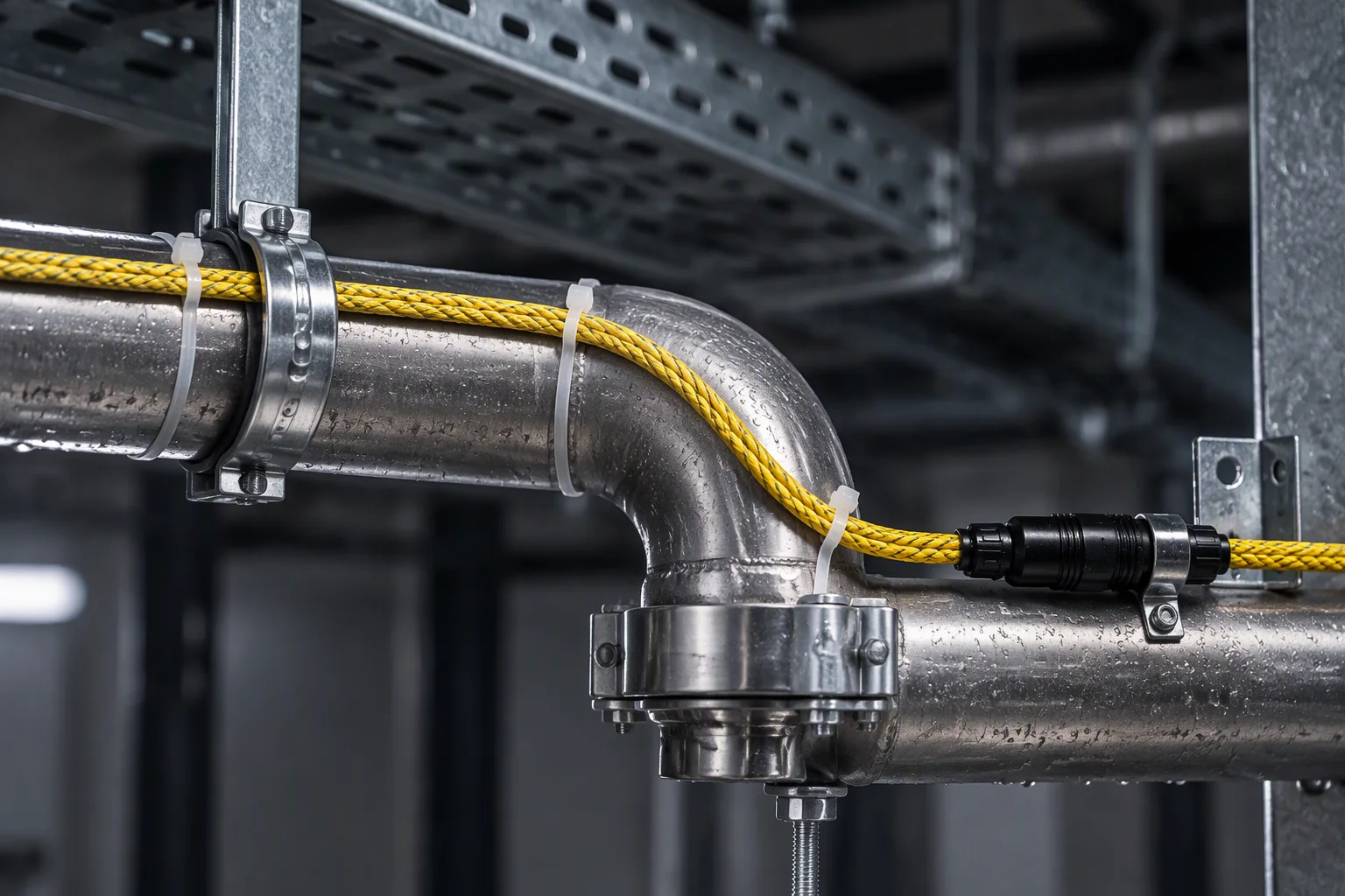
The rope is laid at the pipe, not at the room: it moves when the loop moves.
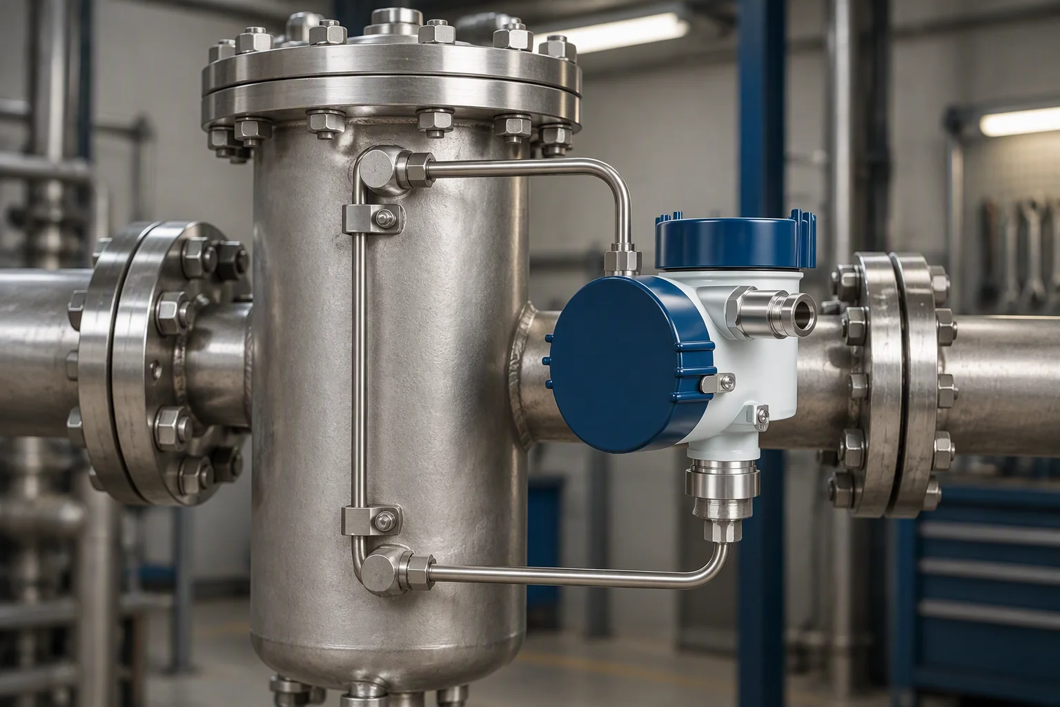
Filter loading is read continuously, because an annual reading cannot show when it moved.
The loop as a mixed-generation row is actually built
Consumables on this section
- 1 ·Row manifolds, one per generation, tied into one loop
- 2 ·Legacy branch, made ten years before the tee beside it
- 3 ·Current row branch, short and direct off the same manifold
- 4 ·Sampling valve at the head of the run, not at the tank
- 5 ·Filter with a differential pressure transmitter on the return
- 6 ·Locating sensing rope along the pipe, 0.1 m resolution
The three files this industry is held as
Three configurations recur where a loop outlives its equipment. Each is held as a file: the loop drawing, the consumable list, the baseline sample and every sample after it.
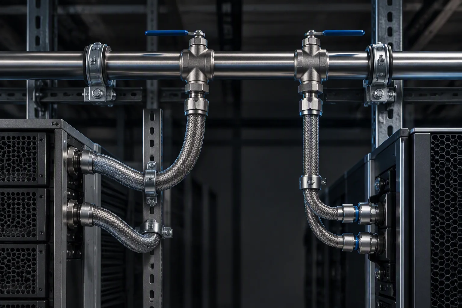
File A. Two generations, one manifold, isolation per branch.
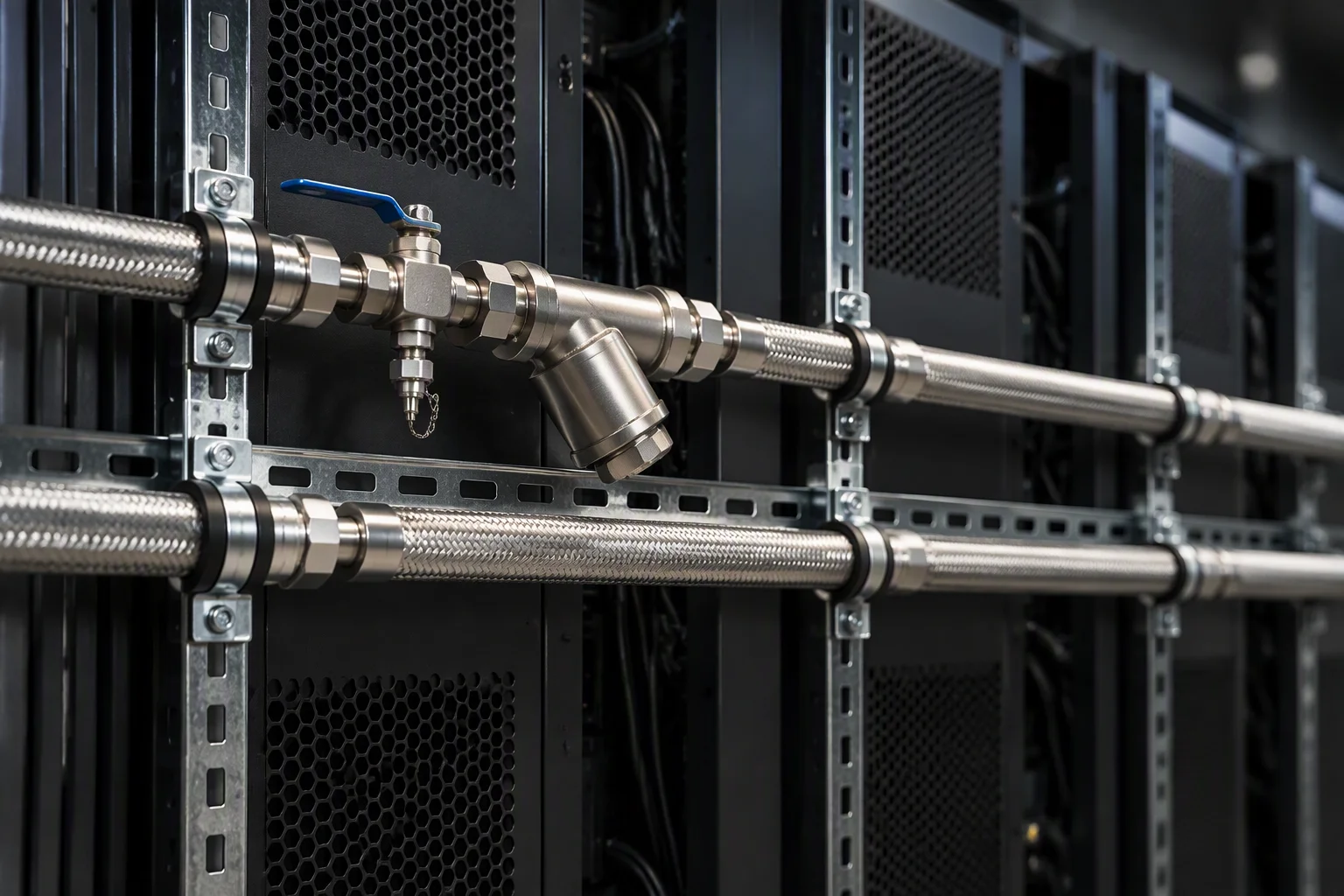
File B. A ring per row, and the sample drawn at the head of it.
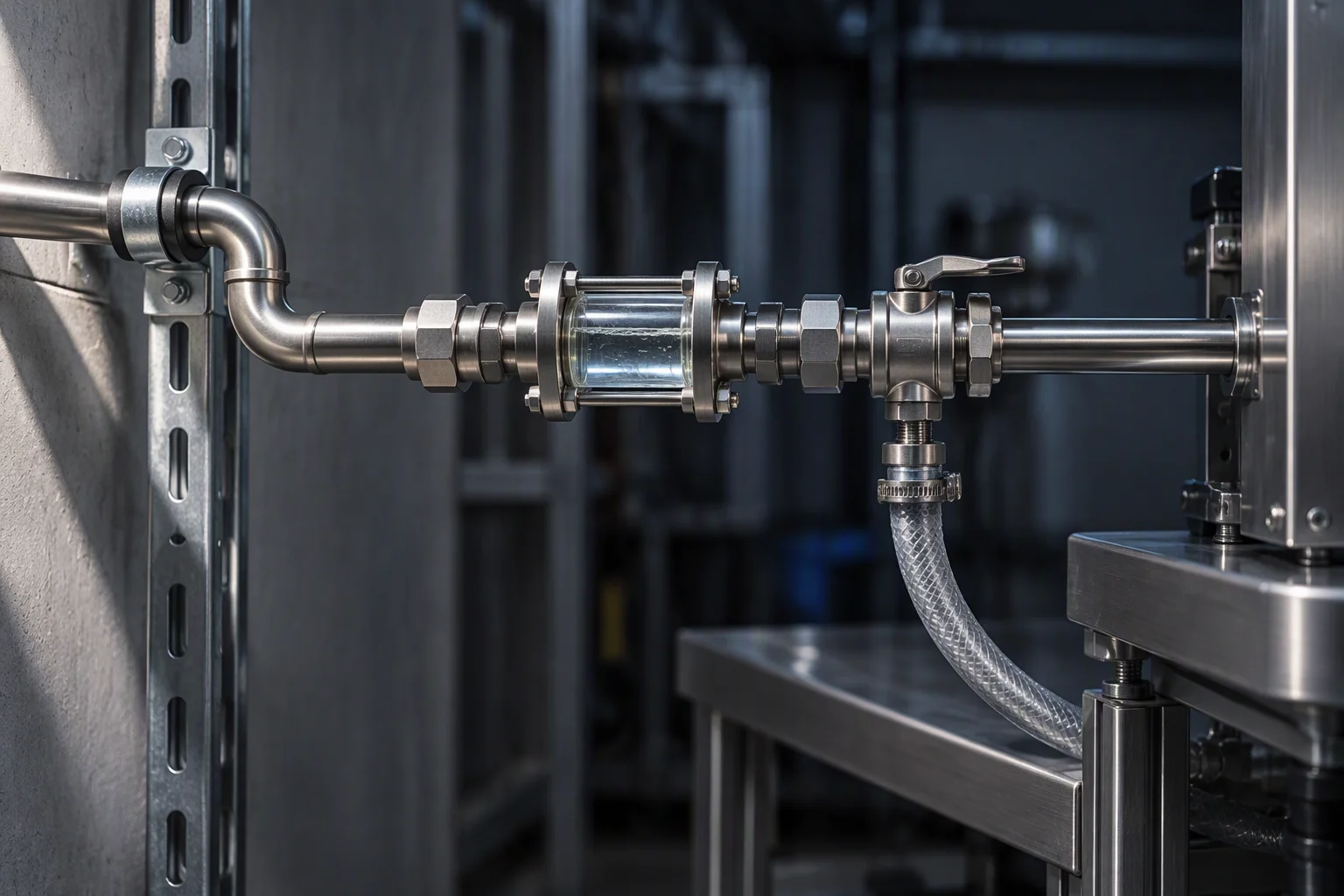
File C. The bench loop: the smallest file in the set, and the same schedule.
The standards a research loop is written against
How those standards are demonstrated
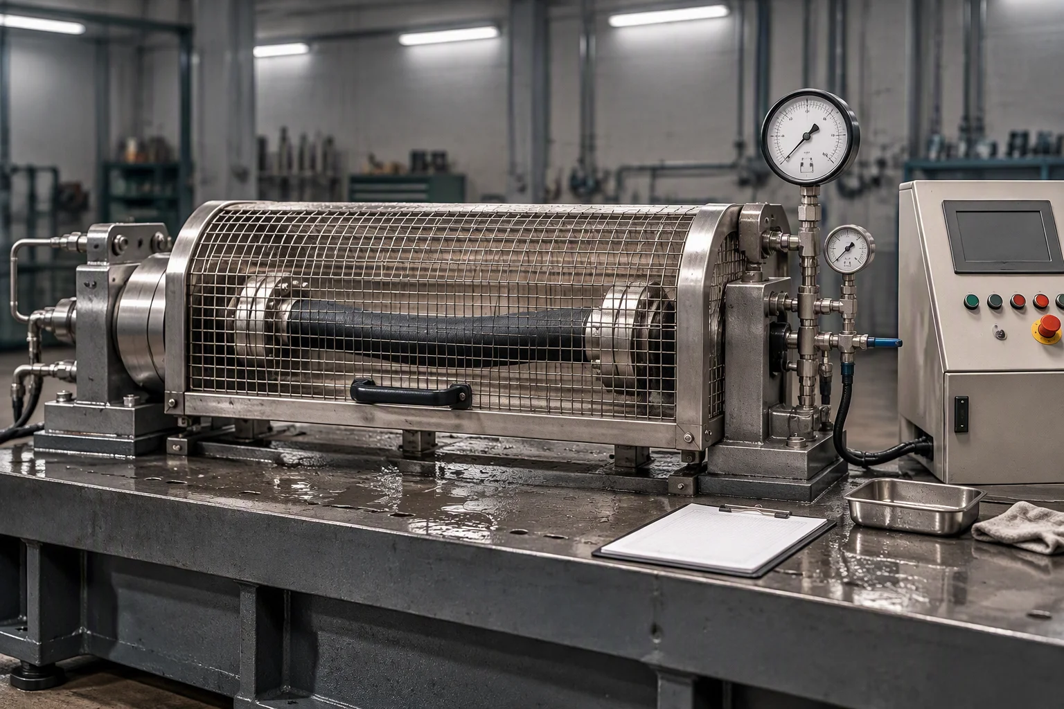
1.38 MPa working and burst above 5.5 MPa, proven per batch rather than per drawing.
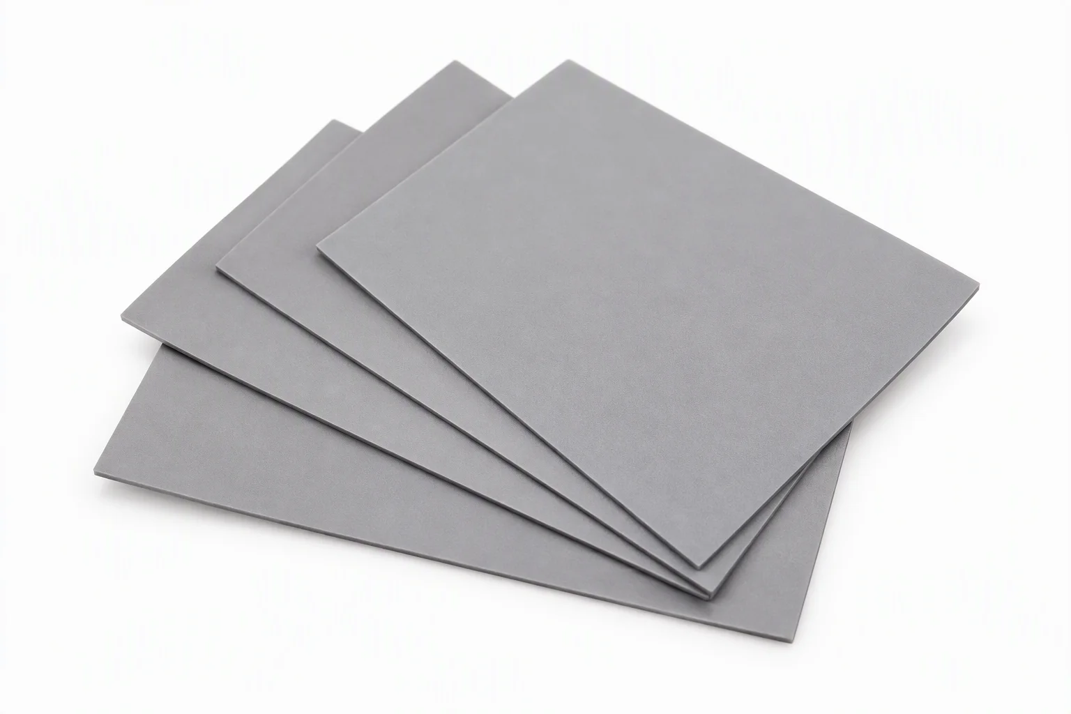
The second thing that gets replaced inside a long-lived loop: the interface, at 1.2–7.5 W/m·K.
A run for a loop that will be topped up and re-branched comes terminated: ends fitted and proof tested before dispatch, so a twelve-year-old line is never cut into on a live row.
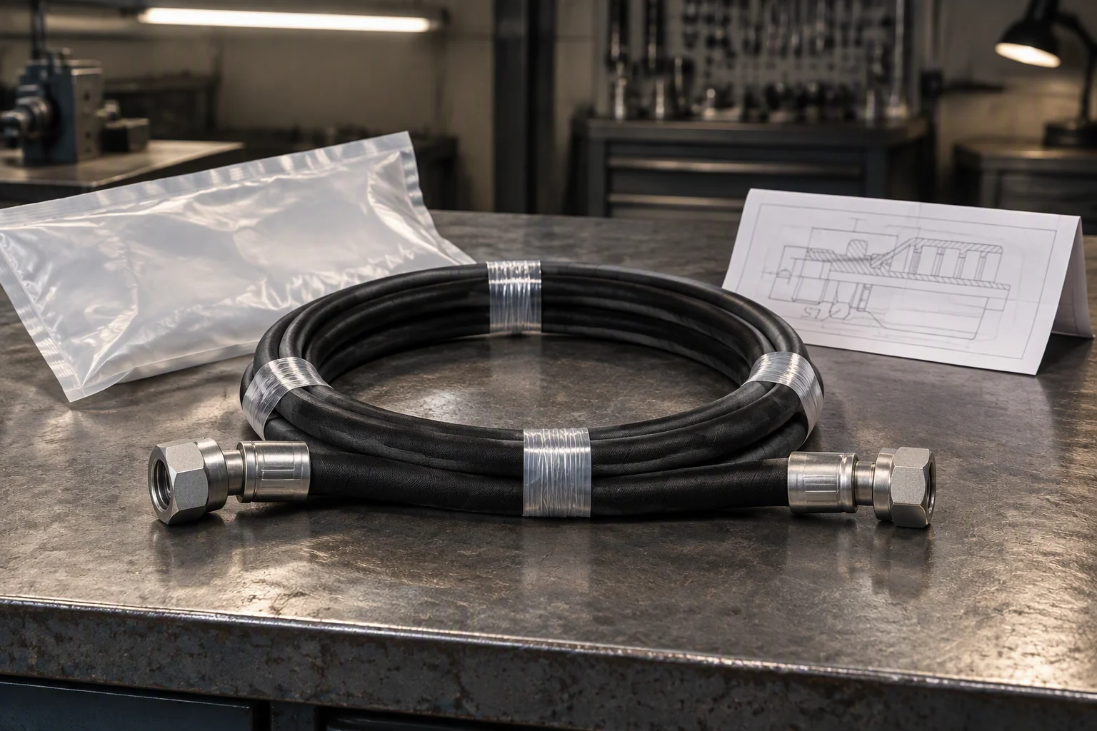
Terminated and tested before dispatch, so the row is never the place the length is decided.
What every one of those files consumes
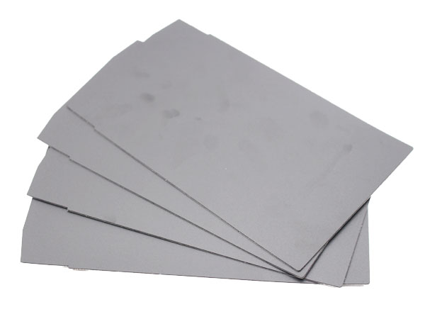
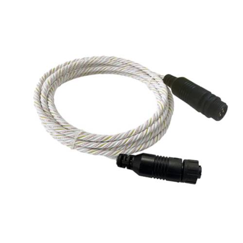
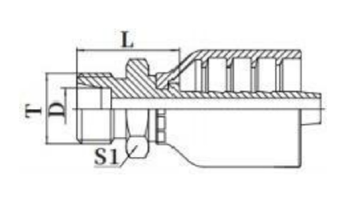
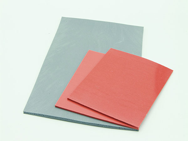
SP 1–4 ·Supply-side samples: a thermal pad at 1.2–7.5 W/m·K, a sensing cable rated 500 m per channel at 0.1 m resolution, a coupling section with its seal groove called out, and the pad sheet a bench loop is cut from.
What stops at the boundary of this sheet
We supply the loop: hose, couplings, seals, filtration, sensing rope and the instruments that read them. The cooling distribution unit and the cold plate are not ours to quote, and neither is the installation, the design or the commissioning of either.
On a long-lived loop that matters for a second reason: the unit sized for the first generation is usually still in place for the third, and it is not what wears out.
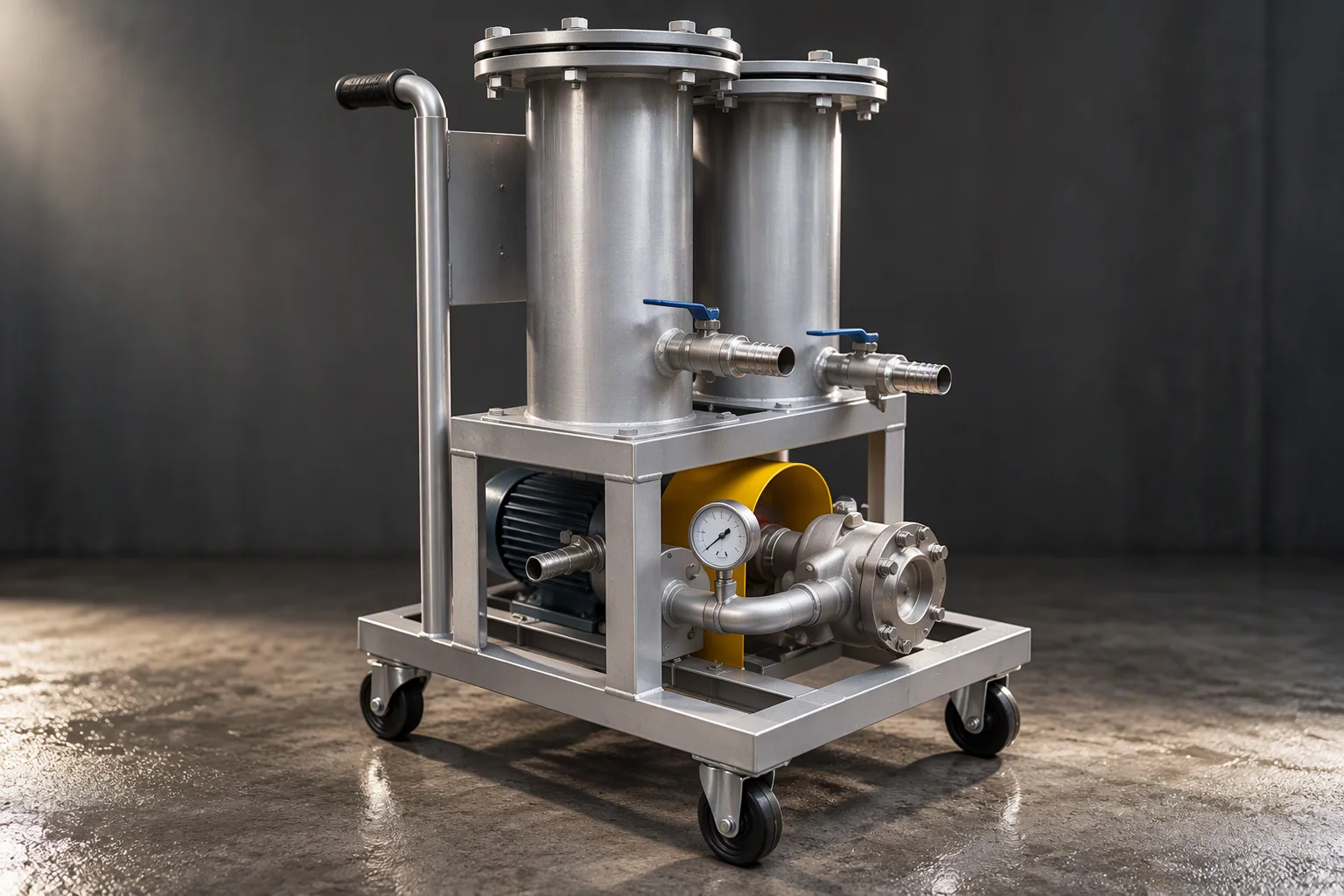
The pumping unit and the tool side stay outside this sheet. What we quote starts at the take-off.
The other sheets in this set
Every sheet in this set is written in the same order: the pain, the schedule it is quoted on, the loop as it is built, the standards, and the configuration files held for it.
Four documents are held for this sheet. Tick the ones you need.
Tick a document, name the row or the bench loop you are planning against, and the file comes back attached.
One business day, with the file attached.
Nothing else on this sheet is a commitment. Price, stock and lead time are not promised here.